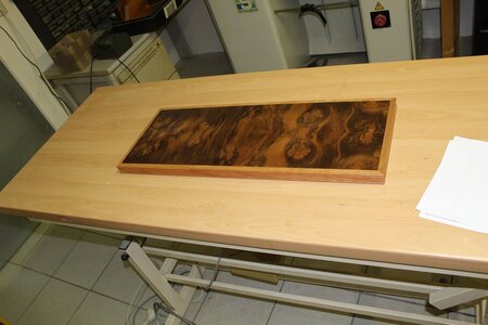
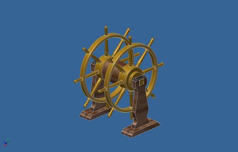
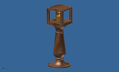
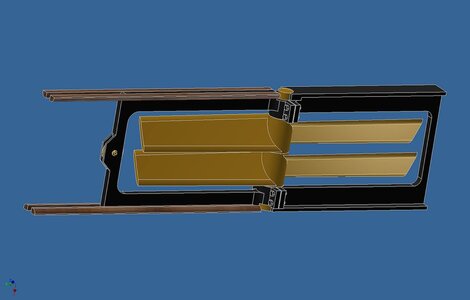
Vaisseau Bretagne von 1855 m1:75

Joined
Jun 28, 2019
Messages
28
Points
68

Ich beginne hier die Vorstellung der Bretagne.
Deren Bau war ein letztes Aufbäumen der Konstrukteure der hölzernen Riesen. Mit dem Aufkommen der Sprenggranaten waren sie veraltet und nur noch bedingt brauchbar.
Die Bretagne litt noch unter einem weiteren Übel. Anscheinend haben die Schiffbauer dem Konstrukteuren nicht getraut, hinsichtlich der ungewöhnlichen Größe und der Länge von 81 m in der Wasserlinie und den Rumpf zu schwer ausgeführt. Der Rumpf tauchte zu tief ein und die Höhe der I. Batterie zum Wasser war um 3/4 m geringer als geplant. In der Praxis, ein Segelschiff liegt immer schräg im Wind. Die unteren Leepforten konnten nur im günstigsten Fall geöffnet werden. Trotz der größeren Verdrängung und den 40 Kanonen mehr, war die Kampfkraft geringer, als die, der Napoleon-Klasse.
Warum also baue ich dieses Schiff?
Es gibt noch kein Modell,
die Pläne des Atlas sind hinreichend,
die Ausführung ist weitgehend wie bei der Napoleon.
Die Verbesserungen sind gut dokumentiert.
Ich kann das Modell also weitgehend stimmig mit dem Original bauen.

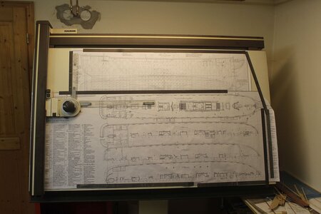
Zu jener Zeit lag ich monatelang mit einem gebrochenen Fuß im Krankenhaus und habe letztlich den Fuß verloren. Als Privatpatient hatte ich ein Einzelzimmer und konnte mir einen Großen Tisch aufstellen lassen. Die Pläne des Archivs hatte ich mir schon vor dem Unfall im Maßstab 1:75 kopieren lassen.
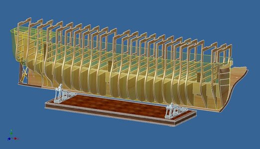
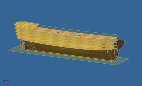
Die 3D-Konstruktion und die Zeichnungsableitung geschah also weitgehend im Krankenhaus.

Nun zur Konstruktion:

google translation:
I begin here the presentation of Bretagne.
Their construction was a last stand of the designers of the wooden giants. With the advent of explosive shells, they were obsolete and of limited use.
Brittany suffered from yet another malady. Apparently, the shipbuilders did not trust the designers, regarding the unusual size and the length of 81 m in the waterline and executed the hull too heavy. The hull dipped too low and the height of the I battery to the water was 3/4 m less than planned. In practice, a sailing ship always lies diagonally in the wind. The lower leeboards could be opened only in the best case. Despite the larger displacement and the 40 guns more, the combat power was less than that, of the Napoleon class.
So why build this ship?
There is no model yet,
the plans of the Atlas are sufficient,
the design is largely the same as the Napoleon.
The improvements are well documented.
So I can build the model largely consistent with the original.

At the time, I was hospitalized for months with a broken foot and ultimately lost the foot. As a private patient, I had a single room and was able to have a large table set up. I had already had the plans of the archive copied at a scale of 1:75 before the accident.
So the 3D design and drawing derivation largely happened in the hospital.

Now to the construction:

Translated with www.DeepL.com/Translator (free version)
B15.jpg

B6.jpg

B7.jpg

B19.jpg

B407.jpg

B491.jpg

B488.jpg

B480.jpg

B404.jpg
 
Last edited by a moderator:
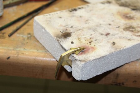
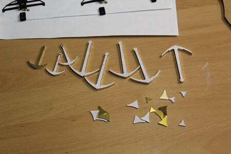
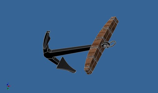
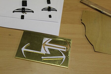
Ein paar weitere Bilder. Die Anker wurden aus 4 mm Messingblech händisch ausgesägt.
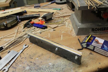
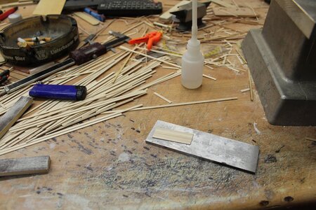
Für die Masten und Rahen habe ich mir eine Vorrichtung für die ogivale Verjüngung gebaut.
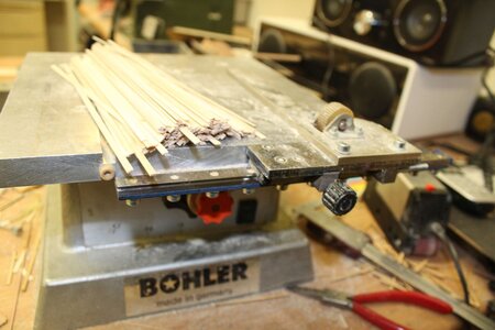
Zuerst wird eine Quadratstange mit etwas Übermaß auf Meiner umgebauten Proxxon FET gesägt. Dann werden die Vierkante auf meiner Aciera F1 gefräst.
Der Überstand der Zunge der Vorrichtung wird auf die Länge der Verjüngung eingestellt. Auf dem Gegenhalter wird mit dem "Spion" die Zunge um das halbe Maß der Verjüngung gebogen. Dann klebe ich die Stange mit doppelseitigem Klebeband auf die Zunge und fräse zwei Seiten (90°) ab. Abfolgend wird die Zunge um das doppelte Maß gebogen und die beiden restlichen Seiten abgefräst. Die doppelte Verjüngung ist notwendig, da der Stab auf einer bereits abgefrästen Fläche auf die Zunge geklebt ist. Der ogivale Vierkant wird nun händisch in etwa zu einem Achtkant gefeilt. Am besten geht dies mit den gezeigten Schleifbrettchen. auf der Drehbank erfolgt dann die Verrundung. Hierzu verwende ich zwei Schleifbrettchen unten und oben. Den Rundlauf merkt man am nachlassenden "Rattern" der Brettchen. Die Genauigkeit liegt bei +-0,1 mm.


A few more pictures. The anchors were hand sawed out of 4 mm brass plate.
For the masts and yards I built myself a jig for the ogival taper.
First, a square bar is sawed with some oversize on my rebuilt Proxxon FET. Then the square edge is milled on my Aciera F1.
The protrusion of the jig's tongue is set to the length of the taper. On the counter jig, the "peephole" is used to bend the tongue by half the dimension of the taper. Then I tape the rod to the tongue with double-sided tape and mill off two sides (90°). Sequentially, the tongue is bent twice the measurement and the remaining two sides are milled off. The double taper is necessary because the bar is taped to the tongue on a surface that has already been milled off. The ogival square is now filed by hand to approximately an octagon. The best way to do this is with the grinding board shown. then on the lathe the rounding is done. I use two grinding boards at the top and bottom. The concentricity is noticeable by the decreasing "chatter" of the boards. The accuracy is +-0.1 mm.

Translated with www.DeepL.com/Translator (free version)

B1034.jpg

B372.jpg

B371.jpg

B370.jpg

B369.jpg

B368.jpg

B367.jpg

B91.jpg

B58.jpg

B57.jpg

B56.jpg

B55.jpg

B54.jpg

B53.jpg
 
Last edited by a moderator:
Hallo Karl,
your details in the design is amazing - it is an extremely interesting project.
I hope to see much much more photos of your work
Many Thanks for starting this building log
 
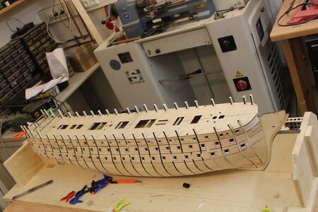
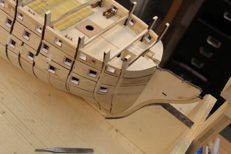
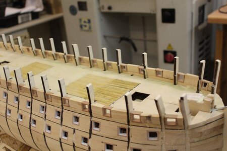
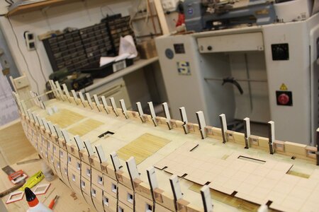
Der Bau des Rumpfes:
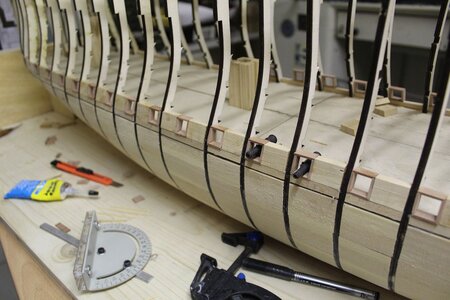
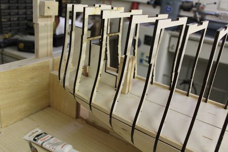
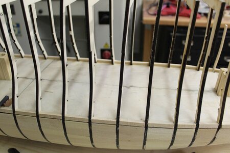
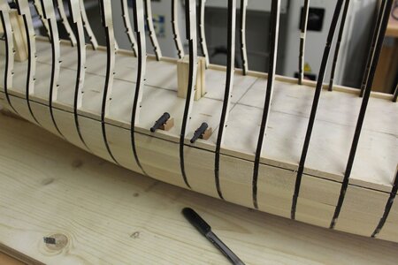
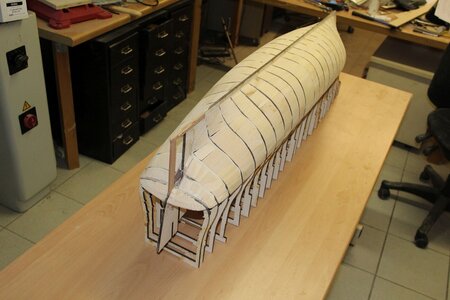
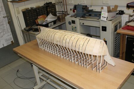
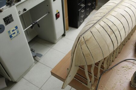
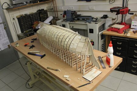
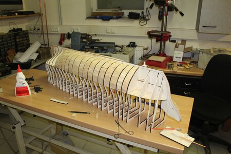
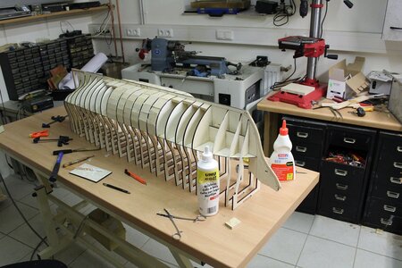
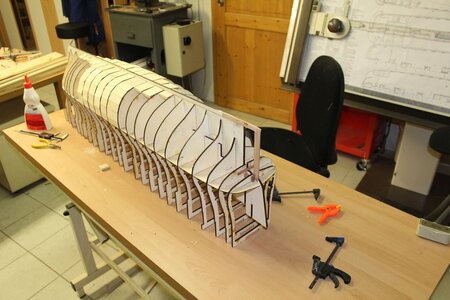
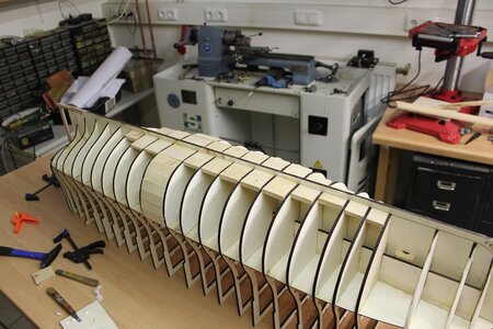
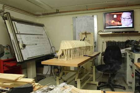
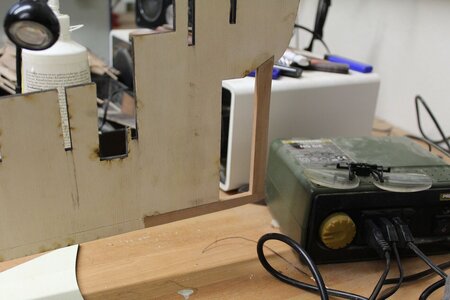
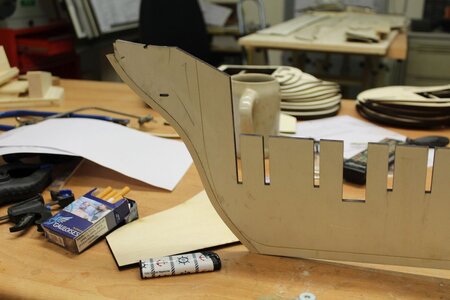
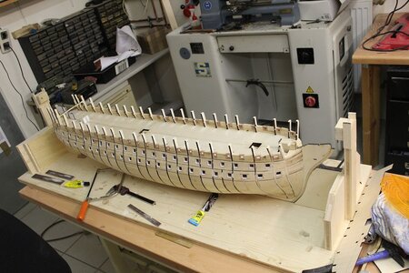
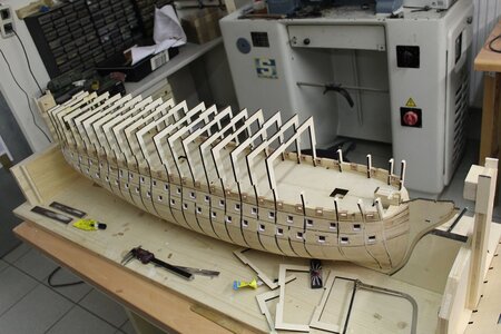
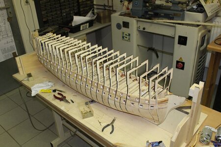
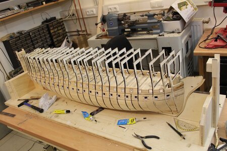
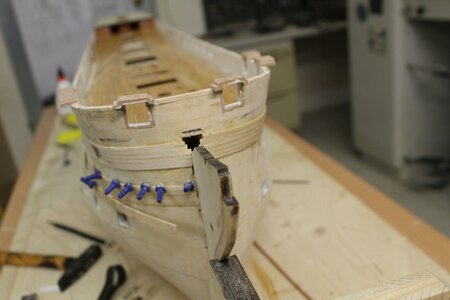
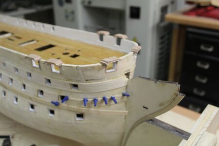
Die Spanten und der Kiel wurden von einem Freund in Böhmen lasergeschnitten. Das Material ist Sperrholz von 5 und 6 mm Dicke.
Die Zeichnungen hatte ich ihm als DWG-Datei geschickt.
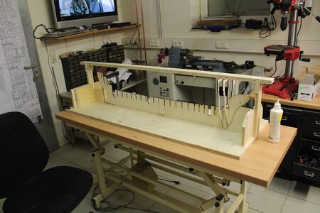
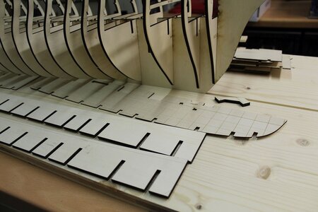
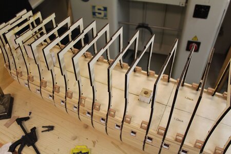
Die Spanten sind auf eine Ebene überhöht und haben eine Nut für für eine Montageleiste, damit die Geradheit des Rumpfes gewährleistet wird. Seitlich der Keillinie und unterhalb des 1. Decks sind, im Abstand von 30 mm, Zahnleisten eingefügt, die der Längsstabilität dienen.
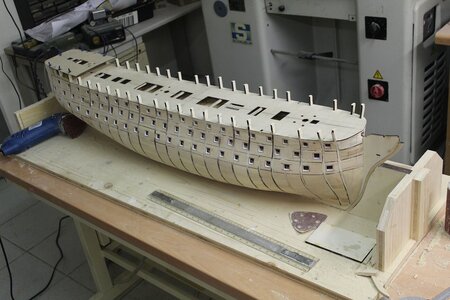
Das Deck ist geviertelt. Untergebaute Streifen vermeiden Stöße zwischen den Deckteilen. Die sichtbaren Teile wurden in Elsbeere ausgeführt.
Der Raum vom Kiel bis zum 1. Decke wurde mit Lindenholz etwas 8 mm dick, gefüllt. Diese "Tarjack-Methode garantiert einen unvergleichlich stabilen Rumpf, ohne Verdrehung.

The construction of the hull:
The frames and keel were laser cut by a friend in Bohemia. The material is plywood of 5 and 6 mm thickness.
I had sent him the drawings as a DWG file.
The formers are raised to one level and have a groove for for a mounting rail to ensure the straightness of the hull. To the side of the wedge line and below the 1st deck, at 30 mm intervals, are inserted toothed strips to provide longitudinal stability.
The deck is quartered. Underbuilt strips avoid joints between the deck parts. The visible parts are made of elsbeer.
The space from the keel to the 1st deck was filled with basswood slightly 8 mm thick. This "Tarjack" method guarantees an incomparably stable hull, without twisting.

Translated with www.DeepL.com/Translator (free version)


B155.jpg

B154.jpg

B150.jpg

B149.jpg

B148.jpg

B146.jpg

B145.jpg

B144.jpg

B143.jpg

B142.jpg

B141.jpg

B140.jpg

B139.jpg

B138.jpg

B137.jpg

B136.jpg

B134.jpg

B133.jpg

B132.jpg

B129.jpg

B128.jpg

B127.jpg

B126.jpg

B125.jpg

B124.jpg
 
Last edited by a moderator:
Very interesting construction method(s) - I like the term "Tarjack-method" ;)
Interesting also to see is the working table, which is movable in height!?!
Was this an old bed from a hospital?
 
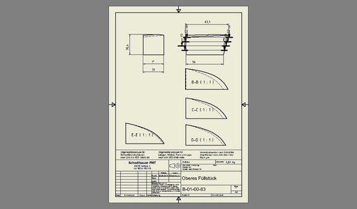
Kennzeichnend meiner Rumpfbaumethode ist, dass die Decks von 1,5 mm dicke aus Fliegersperrholz bis zur Rumpfaußenfläche gezogen sind. Damit habe ich den genauen Deckverlauf an der Rumpfaußenfläche. Auf das Deck wird ein Streifen in einer Dicke eingebracht, der der der Unterkante der Trempelrahmen entspricht.
Die Klötze für die Masten haben deren Innendurchmesser, Sie werden mit ihren Nuten in den Kiel geklebt und garantieren den genauen Mastfall und die lotrechte Ebene zur Wasserlinie. Der Kiel ist ob seiner länge zweigeteilt und mit Laschen verklebt.

Characteristic of my hull construction method is that the decks of 1.5 mm thick aircraft plywood are stretched to the outer surface of the hull. This gives me the exact course of the deck on the outer surface of the hull. A strip is placed on the deck with a thickness corresponding to the lower edge of the footstep frame.

The blocks for the masts have their inner diameter, they are glued into the keel with their grooves and guarantee the exact mast rake and the perpendicular plane to the waterline. The keel is divided in two because of its length and glued with tabs.
 

Attachments

  • B-01-09-0.pdf
    270.7 KB · Views: 50
  • B-01-50-0.pdf
    314.8 KB · Views: 30
  • B-01-57-0.pdf
    236.2 KB · Views: 30
  • B-01-12-6.pdf
    1,003.1 KB · Views: 34
Ich habe den Tisch aus einer Massagebank gebaut. Für Gesunde ist er sehr praktisch. Die Liege kostete um 200.-€.
Mit dem Holzfuß kann ich aber nicht mehr lange im Stehen arbeiten. Ich werde mir deshalb einen Hubtisch kaufen und mit der Arbeitsplatte ausrüsten.

Weiter mit dem Rumpfbau:


I built the table out of a massage bench. It is very useful for healthy people. The beach chair cost around 200 euros.
But with the wooden foot I can no longer work standing for long time. I will therefore buy a lifting table and equip it with the worktop.

Continue with the hull construction:


B179.jpg

B178.jpg

B177.jpg

B176.jpg

B175.jpg

B174.jpg

B173.jpg

B172.jpg

B171.jpg

B170.jpg

B169.jpg

B167.jpg

B162.jpg

B161.jpg
 
Last edited by a moderator:
Wow - impressive such a Later 3 decker
Really a lot of gunports - looking very good (and interesting way of construction)
 
Weiterbau
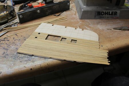
B256 zeigt eine Vorrichtung, die ich aus 3 mm Blech lasern lies. Mit dieser konnte ich eine gleichmäßige und angepasste Verjüngung/Profilierung der Quarterdecksplanken erzielen.

Further construction
B256 is showing a jig I had laser cut from 3 mm sheet metal. With this I was able to achieve an even and adjusted taper/profiling of the quarterdeck planks.

B257.jpg

B256.jpg

B255.jpg

B254.jpg

B253.jpg

B252.jpg

B251.jpg

B250.jpg

B249.jpg

B248.jpg

B247.jpg

B246.jpg

B245.jpg

B244.jpg
 
Last edited by a moderator:
Ich beginne hier die Vorstellung der Bretagne.
Deren Bau war ein letztes Aufbäumen der Konstrukteure der hölzernen Riesen. Mit dem Aufkommen der Sprenggranaten waren sie veraltet und nur noch bedingt brauchbar.
Die Bretagne litt noch unter einem weiteren Übel. Anscheinend haben die Schiffbauer dem Konstrukteuren nicht getraut, hinsichtlich der ungewöhnlichen Größe und der Länge von 81 m in der Wasserlinie und den Rumpf zu schwer ausgeführt. Der Rumpf tauchte zu tief ein und die Höhe der I. Batterie zum Wasser war um 3/4 m geringer als geplant. In der Praxis, ein Segelschiff liegt immer schräg im Wind. Die unteren Leepforten konnten nur im günstigsten Fall geöffnet werden. Trotz der größeren Verdrängung und den 40 Kanonen mehr, war die Kampfkraft geringer, als die, der Napoleon-Klasse.
Warum also baue ich dieses Schiff?
Es gibt noch kein Modell,
die Pläne des Atlas sind hinreichend,
die Ausführung ist weitgehend wie bei der Napoleon.
Die Verbesserungen sind gut dokumentiert.
Ich kann das Modell also weitgehend stimmig mit dem Original bauen.

Zu jener Zeit lag ich monatelang mit einem gebrochenen Fuß im Krankenhaus und habe letztlich den Fuß verloren. Als Privatpatient hatte ich ein Einzelzimmer und konnte mir einen Großen Tisch aufstellen lassen. Die Pläne des Archivs hatte ich mir schon vor dem Unfall im Maßstab 1:75 kopieren lassen.
Die 3D-Konstruktion und die Zeichnungsableitung geschah also weitgehend im Krankenhaus.

Nun zur Konstruktion:

google translation:
I begin here the presentation of Bretagne.
Their construction was a last stand of the designers of the wooden giants. With the advent of explosive shells, they were obsolete and of limited use.
Brittany suffered from yet another malady. Apparently, the shipbuilders did not trust the designers, regarding the unusual size and the length of 81 m in the waterline and executed the hull too heavy. The hull dipped too low and the height of the I battery to the water was 3/4 m less than planned. In practice, a sailing ship always lies diagonally in the wind. The lower leeboards could be opened only in the best case. Despite the larger displacement and the 40 guns more, the combat power was less than that, of the Napoleon class.
So why build this ship?
There is no model yet,
the plans of the Atlas are sufficient,
the design is largely the same as the Napoleon.
The improvements are well documented.
So I can build the model largely consistent with the original.

At the time, I was hospitalized for months with a broken foot and ultimately lost the foot. As a private patient, I had a single room and was able to have a large table set up. I had already had the plans of the archive copied at a scale of 1:75 before the accident.
So the 3D design and drawing derivation largely happened in the hospital.

Now to the construction:

Translated with www.DeepL.com/Translator (free version)
Hallo @Rablok
we wish you alll the BEST and a HAPPY BIRTHDAY
Birthday-Cake
How is your project going? It would be very interesting to see your progress ....
 
Ich beginne hier die Vorstellung der Bretagne.
Deren Bau war ein letztes Aufbäumen der Konstrukteure der hölzernen Riesen. Mit dem Aufkommen der Sprenggranaten waren sie veraltet und nur noch bedingt brauchbar.
Die Bretagne litt noch unter einem weiteren Übel. Anscheinend haben die Schiffbauer dem Konstrukteuren nicht getraut, hinsichtlich der ungewöhnlichen Größe und der Länge von 81 m in der Wasserlinie und den Rumpf zu schwer ausgeführt. Der Rumpf tauchte zu tief ein und die Höhe der I. Batterie zum Wasser war um 3/4 m geringer als geplant. In der Praxis, ein Segelschiff liegt immer schräg im Wind. Die unteren Leepforten konnten nur im günstigsten Fall geöffnet werden. Trotz der größeren Verdrängung und den 40 Kanonen mehr, war die Kampfkraft geringer, als die, der Napoleon-Klasse.
Warum also baue ich dieses Schiff?
Es gibt noch kein Modell,
die Pläne des Atlas sind hinreichend,
die Ausführung ist weitgehend wie bei der Napoleon.
Die Verbesserungen sind gut dokumentiert.
Ich kann das Modell also weitgehend stimmig mit dem Original bauen.

Zu jener Zeit lag ich monatelang mit einem gebrochenen Fuß im Krankenhaus und habe letztlich den Fuß verloren. Als Privatpatient hatte ich ein Einzelzimmer und konnte mir einen Großen Tisch aufstellen lassen. Die Pläne des Archivs hatte ich mir schon vor dem Unfall im Maßstab 1:75 kopieren lassen.
Die 3D-Konstruktion und die Zeichnungsableitung geschah also weitgehend im Krankenhaus.

Nun zur Konstruktion:

google translation:
I begin here the presentation of Bretagne.
Their construction was a last stand of the designers of the wooden giants. With the advent of explosive shells, they were obsolete and of limited use.
Brittany suffered from yet another malady. Apparently, the shipbuilders did not trust the designers, regarding the unusual size and the length of 81 m in the waterline and executed the hull too heavy. The hull dipped too low and the height of the I battery to the water was 3/4 m less than planned. In practice, a sailing ship always lies diagonally in the wind. The lower leeboards could be opened only in the best case. Despite the larger displacement and the 40 guns more, the combat power was less than that, of the Napoleon class.
So why build this ship?
There is no model yet,
the plans of the Atlas are sufficient,
the design is largely the same as the Napoleon.
The improvements are well documented.
So I can build the model largely consistent with the original.

At the time, I was hospitalized for months with a broken foot and ultimately lost the foot. As a private patient, I had a single room and was able to have a large table set up. I had already had the plans of the archive copied at a scale of 1:75 before the accident.
So the 3D design and drawing derivation largely happened in the hospital.

Now to the construction:

Translated with www.DeepL.com/Translator (free version)

View attachment 298810

View attachment 298811

View attachment 298813

View attachment 298814

View attachment 298815

View attachment 298816

View attachment 298817

View attachment 298818

View attachment 298819
Hallo @Rablok
we wish you alll the BEST and a HAPPY BIRTHDAY
Birthday-Cake
How is your project going? It would be very interesting to see your progress ....
 
Hallo @Rablok
we wish you alll the BEST and a HAPPY BIRTHDAY
Birthday-Cake
How is your project going? It would be very interesting to see your progress ....
Hallo,
I am sorry to inform you, that Rablok alias Karl Schedelbauer passed away some months ago.
Rest in Peace my friend
 
Back
Top