You are using an out of date browser. It may not display this or other websites correctly.
You should upgrade or use an alternative browser.
You should upgrade or use an alternative browser.
Vasa - 1:65 DeAgostini [COMPLETED BUILD]
- Thread starter dockattner
- Start date
- Watchers 145
Just saying...not sure you ever were sane if you had already decided to rig ALL those hidden guns. And did you plank the hidden deck as well? I suppose you're treenailing those planks too.I though the meaning clear enough. I'm behind Paul in my build, and am doing scratch building much of the interior of HMS Sovereign of the Seas, including rigging all cannon carriages, 100 guns worth. Why? Because... someone has to.
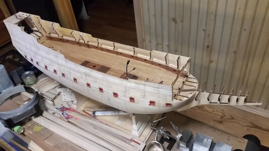
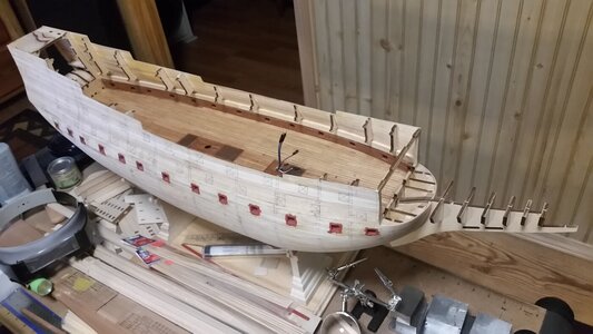
Progress so far...
View attachment 257013
Kurt, I just glommed onto your build log for the SotS. I don’t know why I wasn’t following you. I watched your Couronne avidly. My apologies for the previous remarks. You are obviously not insane. Just obsessed. (Sorry, Paul, for the intrusion.) If anyone has not tuned in to Kurt’s build @DARIVS ARCHITECTVS, I highly recommend it.I though the meaning clear enough. I'm behind Paul in my build, and am doing scratch building much of the interior of HMS Sovereign of the Seas, including rigging all cannon carriages, 100 guns worth. Why? Because... someone has to.
Progress so far...
View attachment 257013
- Joined
- Jul 12, 2021
- Messages
- 92
- Points
- 143

Looking good so far, Paul! There are a lot of odd engineering choices in the kit, mostly because it was designed to be a part works release, with weekly installments, and everything had to fit on a letter-sized card (thus the four-part keel and multi-part frames), but it mostly goes together very well. The accuracy is pretty good, they made maximum use of the the drawings we supplied, and we did some digital modelling of specific items just for the kit (such as the anchors) so they would not have to use generic parts. The painting instructions are very good, except that they want you to paint the gun carriages red (no idea where that came from), when the originals were painted black (the paint receipt survives). Once it gets to the rigging stage, it is rather over-simplified, but you can upgrade that to your heart's content and there is plenty of data available.As an aside, I traced out a few of the frames before gluing them to the false keel (why is it called false?). By calculating the thickness of the future hull planking I am hoping to fabricate a dry dock/carriage to use later in the construction. Or at least that seems like a good idea...
A false keel is an extra timber on the bottom of the keel to build up its depth for more strength (as opposed to a shoe or wormshoe, which is a thin, sacrificial plank to handle abrasion and marine growth). No idea why they call it this in the kit, as Vasa does not have a false keel, just a keel, with a hog on top of it (a doubling timber to act as a nailer for the first plank).
If you need specific information that is not in your instructions or on the internet, you can post here or write to me and I can check things on the ship - it gives me an excuse to get out of my office and go crawl around in the hull or up in the rigging.
Fred Hocker
Anyone interested in the work Marc is describing here (bolt replacement) might enjoy this video:A major part of the on-going work of the Museet is to pay meticulous attention to the ceaseless degradation of Vasa's timbers. One of the more recent efforts was to replace the restoration iron replacement fasteners with very high-grade stainless steel because the iron was reacting with the residual sulfur content of the preserved timbers and leading to cellular, structural compromise of the oak. Painting her to her original appearance would, indeed, be a vivid display, but it would be very much to the detriment of her long-term preservation; out of sight, out of mind.
I have long thought that it would be one of the more fascinating wooden ship re-constructions to re-build Vasa, but to do so with modern engineering so that the resulting vessel were actually sea-worthy in a stiff-wind. I wouldn't hesitate to paint that ship! Just think of the possibilities; day sails, cocktails in-hand, aboard the Vasa!
Preserving the Vasa
A ride on a re-built Vasa would get me on a plane in about 30 seconds!A major part of the on-going work of the Museet is to pay meticulous attention to the ceaseless degradation of Vasa's timbers. One of the more recent efforts was to replace the restoration iron replacement fasteners with very high-grade stainless steel because the iron was reacting with the residual sulfur content of the preserved timbers and leading to cellular, structural compromise of the oak. Painting her to her original appearance would, indeed, be a vivid display, but it would be very much to the detriment of her long-term preservation; out of sight, out of mind.
I have long thought that it would be one of the more fascinating wooden ship re-constructions to re-build Vasa, but to do so with modern engineering so that the resulting vessel were actually sea-worthy in a stiff-wind. I wouldn't hesitate to paint that ship! Just think of the possibilities; day sails, cocktails in-hand, aboard the Vasa
You know what I think would make for an interesting build: a model of the Vasa as it exists in its preserved state at the museum today...
Well Marc, considering the fact that I like your model more than mine, I guess we are evenPaul, if your build-log were a racehorse in the Kentucky derby, I'd bet on it every time! Triple Crown? Triple me down! As soon as I'm caught up, you go ahead and make all of this remarkable progress. I'm beginning to think that your "professional career" is really a well-curated sham, and that you just work on this ship 24/7 like some sort of dexterous cyborg; "I'LL BE BACK, to ever so minutely detail these visible gun carriages, with their layered, nailed trucks and perfectly scaled block tackles!" JUST WATCH ME, SUCKA'. Oh, yes, I am watching - albeit on a delay.
I'm going to say something that may sound like false flattery, but I can assure you that I am 100% serious. I really think that I like your model considerably more than my own. Considering my own investment in time, that is really saying something - as you well know. Personally, while I know "perfection" is un-attainable, I always strive to maintain consistently scrutable results. You really deliver on that! The close-ups tell all, and the story is a real ripper. This is just one of the best models ever! Onward, my friend.
 .
.But lest you think I am being too dismissive of your compliment... I am humbled beyond words. Literally. I read this post yesterday but could not respond because I was speechless. I don't even think of my work as being in the same league as yours. Indeed, I was even toying with the idea of coming out to see it in person at your upcoming meeting.
I will grant you that this iteration of the Vasa might be unique. Maybe even unexpected given my lack of experience. But I am simply trying to build what I see in pictures - pictures of things I don't even know the names of in most cases. Perhaps my lack of experience has freed me from some of the constraints of traditional ship building. For example, it never even occurred to me to make the hull planking uniform - because on the ship it's not uniform! But my lack of experience has also introduced all kinds of errors - ones that I see every time I look at the ship - but also ones that I must ignore or I will become caught up in the morass of my own creation.
This is all just a hobby for me. Something to do to work out my creative juices and deploy some of the hand skills I have been gifted with.
Oh - as for the close-ups - UGH! If one of them ever turns out as good as I think I have done I will certainly fall over dead. I truly despise macros but I think they belong in the forum as they are the truest measure of one's work - and a cause for all of us to remain humble and sympathetic when viewing the work of others.
Thank you for your kindness extended toward me Marc. I hope you know that the admiration is mutual.
Welcome to my build log Mr. Hocker (@fred.hocker). I am simultaneously excited and frightened to see you here. You were kind to send me some drawings of the ship's boat a few months ago so you have already helped me out (at least with what I hope will be a future mini-project to be displayed alongside the mother ship).Looking good so far, Paul! There are a lot of odd engineering choices in the kit, mostly because it was designed to be a part works release, with weekly installments, and everything had to fit on a letter-sized card (thus the four-part keel and multi-part frames), but it mostly goes together very well. The accuracy is pretty good, they made maximum use of the the drawings we supplied, and we did some digital modelling of specific items just for the kit (such as the anchors) so they would not have to use generic parts. The painting instructions are very good, except that they want you to paint the gun carriages red (no idea where that came from), when the originals were painted black (the paint receipt survives). Once it gets to the rigging stage, it is rather over-simplified, but you can upgrade that to your heart's content and there is plenty of data available.
A false keel is an extra timber on the bottom of the keel to build up its depth for more strength (as opposed to a shoe or wormshoe, which is a thin, sacrificial plank to handle abrasion and marine growth). No idea why they call it this in the kit, as Vasa does not have a false keel, just a keel, with a hog on top of it (a doubling timber to act as a nailer for the first plank).
If you need specific information that is not in your instructions or on the internet, you can post here or write to me and I can check things on the ship - it gives me an excuse to get out of my office and go crawl around in the hull or up in the rigging.
Fred Hocker
If you choose to continue to work your way through this build log you will learn that I am no ship modelling expert. But I am having the time of my life and I would welcome your comments and guidance. This SOS forum is a delight. Your addition to it is most welcome!
Dood... I DID.Just saying...not sure you ever were sane if you had already decided to rig ALL those hidden guns. And did you plank the hidden deck as well? I suppose you're treenailing those planks too.
See? That's the LOWER gun deck. Still looking for a sufficiently detailed figurine for the captain's dog . . .
Yeah, I just got through looking at your log. Unbelievable! Unglaublich! ¡No lo creo!Dood... I DID.
See? That's the LOWER gun deck. Still looking for a sufficiently detailed figurine for the captain's dog . . .
View attachment 257158
Hey Paul, a really terrific ongoing build and with Fred Hocker providing his knowledge and guidance you are definitely going to have a masterpiece.
I have zero expectations that you would travel all that distance, but it would be a pleasure to meet you, if you do.Well Marc, considering the fact that I like your model more than mine, I guess we are even.
But lest you think I am being too dismissive of your compliment... I am humbled beyond words. Literally. I read this post yesterday but could not respond because I was speechless. I don't even think of my work as being in the same league as yours. Indeed, I was even toying with the idea of coming out to see it in person at your upcoming meeting.
I will grant you that this iteration of the Vasa might be unique. Maybe even unexpected given my lack of experience. But I am simply trying to build what I see in pictures - pictures of things I don't even know the names of in most cases. Perhaps my lack of experience has freed me from some of the constraints of traditional ship building. For example, it never even occurred to me to make the hull planking uniform - because on the ship it's not uniform! But my lack of experience has also introduced all kinds of errors - ones that I see every time I look at the ship - but also ones that I must ignore or I will become caught up in the morass of my own creation.
This is all just a hobby for me. Something to do to work out my creative juices and deploy some of the hand skills I have been gifted with.
Oh - as for the close-ups - UGH! If one of them ever turns out as good as I think I have done I will certainly fall over dead. I truly despise macros but I think they belong in the forum as they are the truest measure of one's work - and a cause for all of us to remain humble and sympathetic when viewing the work of others.
Thank you for your kindness extended toward me Marc. I hope you know that the admiration is mutual.
Exactly what I plan on doing with the Constitution when I finally get it. I also plan on installing lights below.Dood... I DID.
See? That's the LOWER gun deck. Still looking for a sufficiently detailed figurine for the captain's dog . . .
View attachment 257158
Paul, you are an inspiration.
Hello Friends,
As advertised, I turned my attention recently to the upper railings. For an experienced modeler I believe these would have been routine - but once again I found myself struggling (trying to figure out how to fabricate and attach these very fragile components).
Let's begin with the goal. In the image below notice that there is a head rail (a cap rail) and then an upper rail. Whereas the cap rail sits on top of the frames the upper rail sits alongside a post. The post has a soft rounding of the inboard edge (OK, that part may not be clear in this particular picture but it's there).
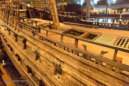
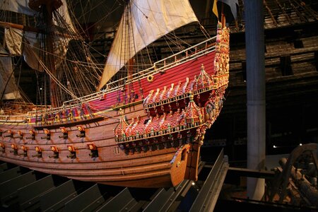
What I should have done is install the posts at the time I built the cap rails (indeed, the post should have passed through the cap rail) - but I missed that detail. Notice, also, that the upper rail does not follow the 'stepping' of the cap rail as the railing system proceeds to the stern. Here is a picture of the 1:10 that will make that more clear:
The first thing I did was fabricate the railing components:
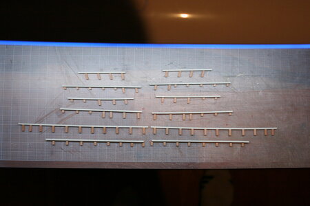
Getting the posts the correct length and cut at the proper bevel (they are not 90 degrees to the top of the cap rail both front to back as well as left to right) was tricky business. There is probably an easy way to do this but it escaped me. I essentially cut and beveled them one by one.
I then attached each rail segment to the ship:
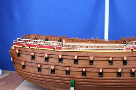
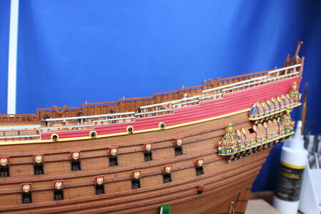
So far so good. But that's where the success parade came to an end. Each of these rail segments is joined to it's neighbor by a curved piece of railing (see the images above from the museum ship and the 1:10). Here the task before me exceeded my capabilities.
First I tried to bend the 2x2 mm pear strip I was using for the upper rail. Fail. The wood could not tolerate the tight radius needed. No amount of soaking / steaming / heating worked. Next, I tried to make the curved piece by laminating thinner strips. This worked much better but I wasn't able to customize the shape needed for each individual curved bit (at least not without making 12 custom jigs).
In the end I resorted to making a cardstock template fashioned at each curved rail location and cutting (sanding / filing) from dimensional pear strips I had on hand. This worked but only barely. In my mind I pictured more precision but the 'curves' are quite small and hard to handle for cutting and shaping. Again, there is probably a way to do these better but not by this guy (or at least not today)...
Here is what I ended up with:
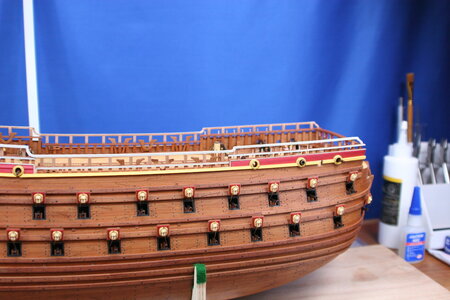
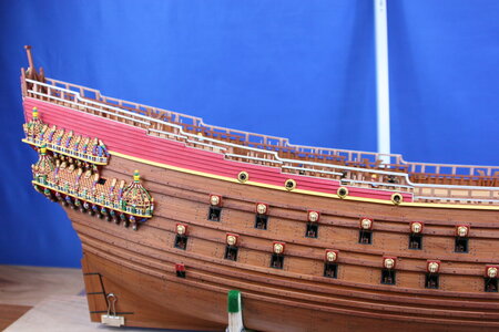
But now this post takes a turn for the worse. The upper railing is profiled with a central groove running along its length. That's no problem on the straight runs - but I simply could not get the groove profile nice and clean on the curved pieces. The time being spent on this was becoming a bit silly so I left it like this for now. Perhaps this job is done - perhaps it will be revisited.
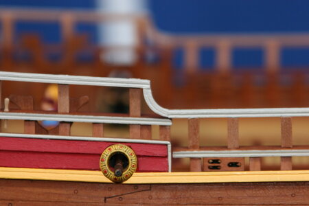
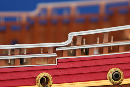
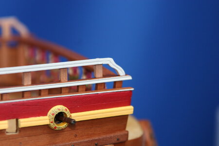
I know. I wasn't impressed either , but at conversational distance it looks better than under close-up! Of course the pear wood still needs oil treatment.
Oh, and my next ship will not have paint anywhere near it. I am done with painted wood!
Thanks for stopping by; I enjoy the company.
As advertised, I turned my attention recently to the upper railings. For an experienced modeler I believe these would have been routine - but once again I found myself struggling (trying to figure out how to fabricate and attach these very fragile components).
Let's begin with the goal. In the image below notice that there is a head rail (a cap rail) and then an upper rail. Whereas the cap rail sits on top of the frames the upper rail sits alongside a post. The post has a soft rounding of the inboard edge (OK, that part may not be clear in this particular picture but it's there).

What I should have done is install the posts at the time I built the cap rails (indeed, the post should have passed through the cap rail) - but I missed that detail. Notice, also, that the upper rail does not follow the 'stepping' of the cap rail as the railing system proceeds to the stern. Here is a picture of the 1:10 that will make that more clear:

The first thing I did was fabricate the railing components:

Getting the posts the correct length and cut at the proper bevel (they are not 90 degrees to the top of the cap rail both front to back as well as left to right) was tricky business. There is probably an easy way to do this but it escaped me. I essentially cut and beveled them one by one.
I then attached each rail segment to the ship:


So far so good. But that's where the success parade came to an end. Each of these rail segments is joined to it's neighbor by a curved piece of railing (see the images above from the museum ship and the 1:10). Here the task before me exceeded my capabilities.
First I tried to bend the 2x2 mm pear strip I was using for the upper rail. Fail. The wood could not tolerate the tight radius needed. No amount of soaking / steaming / heating worked. Next, I tried to make the curved piece by laminating thinner strips. This worked much better but I wasn't able to customize the shape needed for each individual curved bit (at least not without making 12 custom jigs).
In the end I resorted to making a cardstock template fashioned at each curved rail location and cutting (sanding / filing) from dimensional pear strips I had on hand. This worked but only barely. In my mind I pictured more precision but the 'curves' are quite small and hard to handle for cutting and shaping. Again, there is probably a way to do these better but not by this guy (or at least not today)...
Here is what I ended up with:


But now this post takes a turn for the worse. The upper railing is profiled with a central groove running along its length. That's no problem on the straight runs - but I simply could not get the groove profile nice and clean on the curved pieces. The time being spent on this was becoming a bit silly so I left it like this for now. Perhaps this job is done - perhaps it will be revisited.


I know. I wasn't impressed either
Oh, and my next ship will not have paint anywhere near it. I am done with painted wood!
Thanks for stopping by; I enjoy the company.
It looks really good Paul.
I'm getting really close to cutting down out pear tree.......
I'm getting really close to cutting down out pear tree.......
Looks fantastic to me, considering the small scale. The only way to tackle delicate scratch work like this is one small piece at a time. That includes making cardboard patterns that help plan cutting the wooden parts, and changing techniques to make shapes from bending to stock removal, for example, on difficult curved parts. As for the grooves, you can use gouges, Dremel, and riffler files to carefully cut them. Luckily, tiny imperfections in cutting and joinery are hidden by paint on your rails.Hello Friends,
As advertised, I turned my attention recently to the upper railings. For an experienced modeler I believe these would have been routine - but once again I found myself struggling (trying to figure out how to fabricate and attach these very fragile components).
Let's begin with the goal. In the image below notice that there is a head rail (a cap rail) and then an upper rail. Whereas the cap rail sits on top of the frames the upper rail sits alongside a post. The post has a soft rounding of the inboard edge (OK, that part may not be clear in this particular picture but it's there).
View attachment 257608
What I should have done is install the posts at the time I built the cap rails (indeed, the post should have passed through the cap rail) - but I missed that detail. Notice, also, that the upper rail does not follow the 'stepping' of the cap rail as the railing system proceeds to the stern. Here is a picture of the 1:10 that will make that more clear:
View attachment 257609
The first thing I did was fabricate the railing components:
View attachment 257610
Getting the posts the correct length and cut at the proper bevel (they are not 90 degrees to the top of the cap rail both front to back as well as left to right) was tricky business. There is probably an easy way to do this but it escaped me. I essentially cut and beveled them one by one.
I then attached each rail segment to the ship:
View attachment 257611
View attachment 257612
So far so good. But that's where the success parade came to an end. Each of these rail segments is joined to it's neighbor by a curved piece of railing (see the images above from the museum ship and the 1:10). Here the task before me exceeded my capabilities.
First I tried to bend the 2x2 mm pear strip I was using for the upper rail. Fail. The wood could not tolerate the tight radius needed. No amount of soaking / steaming / heating worked. Next, I tried to make the curved piece by laminating thinner strips. This worked much better but I wasn't able to customize the shape needed for each individual curved bit (at least not without making 12 custom jigs).
In the end I resorted to making a cardstock template fashioned at each curved rail location and cutting (sanding / filing) from dimensional pear strips I had on hand. This worked but only barely. In my mind I pictured more precision but the 'curves' are quite small and hard to handle for cutting and shaping. Again, there is probably a way to do these better but not by this guy (or at least not today)...
Here is what I ended up with:
View attachment 257613
View attachment 257614
But now this post takes a turn for the worse. The upper railing is profiled with a central groove running along its length. That's no problem on the straight runs - but I simply could not get the groove profile nice and clean on the curved pieces. The time being spent on this was becoming a bit silly so I left it like this for now. Perhaps this job is done - perhaps it will be revisited.
View attachment 257615
View attachment 257617
View attachment 257616
I know. I wasn't impressed either, but at conversational distance it looks better than under close-up! Of course the pear wood still needs oil treatment.
Oh, and my next ship will not have paint anywhere near it. I am done with painted wood!
Thanks for stopping by; I enjoy the company.
As for joinery, having the posts go through first layer of rail is too delicate, you have good chance of snapping something. If you can hide the original joinery method by simpler methods of attaching the parts, like lap or butt joints reinforced by wire pins inside the posts, you won't breaking things as you are making things.
As for wood bending to make the curved parts, one idea is to switch woods. Use bending birch instead of pear. You're going to paint it anyway. Bending birch is very flexible and has a fine grain. You can bend it dry, but soaked wet is best, and the wood actually feels a bit rubbery as you work it.
I think you did a masterful job choosing the methods to accomplish detailed rails. You chose carefully what techniques to use and where, formed a plan on how to make the joints and details, and did hours of futz work to make it happen. (Was ist "futz work" auf Deutsch, Uwe? Furzenwerk? in Yiddish it's "arumfartzen" or "farting around", but I digress). The end result looks great. This is what scratch building is all about.
Last edited:
Paul, hello. The task is certainly not an easy one. But such curved elements are, of course, better cut from a single piece in shape. Which is exactly what you did. It turned out great. In such places, there is always difficulty in matching the elements with each other. Here only files and sandpaper.Hello Friends,
As advertised, I turned my attention recently to the upper railings. For an experienced modeler I believe these would have been routine - but once again I found myself struggling (trying to figure out how to fabricate and attach these very fragile components).
Let's begin with the goal. In the image below notice that there is a head rail (a cap rail) and then an upper rail. Whereas the cap rail sits on top of the frames the upper rail sits alongside a post. The post has a soft rounding of the inboard edge (OK, that part may not be clear in this particular picture but it's there).
View attachment 257608
What I should have done is install the posts at the time I built the cap rails (indeed, the post should have passed through the cap rail) - but I missed that detail. Notice, also, that the upper rail does not follow the 'stepping' of the cap rail as the railing system proceeds to the stern. Here is a picture of the 1:10 that will make that more clear:
View attachment 257609
The first thing I did was fabricate the railing components:
View attachment 257610
Getting the posts the correct length and cut at the proper bevel (they are not 90 degrees to the top of the cap rail both front to back as well as left to right) was tricky business. There is probably an easy way to do this but it escaped me. I essentially cut and beveled them one by one.
I then attached each rail segment to the ship:
View attachment 257611
View attachment 257612
So far so good. But that's where the success parade came to an end. Each of these rail segments is joined to it's neighbor by a curved piece of railing (see the images above from the museum ship and the 1:10). Here the task before me exceeded my capabilities.
First I tried to bend the 2x2 mm pear strip I was using for the upper rail. Fail. The wood could not tolerate the tight radius needed. No amount of soaking / steaming / heating worked. Next, I tried to make the curved piece by laminating thinner strips. This worked much better but I wasn't able to customize the shape needed for each individual curved bit (at least not without making 12 custom jigs).
In the end I resorted to making a cardstock template fashioned at each curved rail location and cutting (sanding / filing) from dimensional pear strips I had on hand. This worked but only barely. In my mind I pictured more precision but the 'curves' are quite small and hard to handle for cutting and shaping. Again, there is probably a way to do these better but not by this guy (or at least not today)...
Here is what I ended up with:
View attachment 257613
View attachment 257614
But now this post takes a turn for the worse. The upper railing is profiled with a central groove running along its length. That's no problem on the straight runs - but I simply could not get the groove profile nice and clean on the curved pieces. The time being spent on this was becoming a bit silly so I left it like this for now. Perhaps this job is done - perhaps it will be revisited.
View attachment 257615
View attachment 257617
View attachment 257616
I know. I wasn't impressed either, but at conversational distance it looks better than under close-up! Of course the pear wood still needs oil treatment.
Oh, and my next ship will not have paint anywhere near it. I am done with painted wood!
Thanks for stopping by; I enjoy the company.
Floor, it still needs to dry for about 3 yearsIt looks really good Paul.
I'm getting really close to cutting down out pear tree.......


