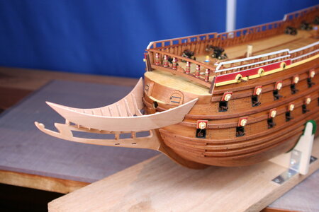
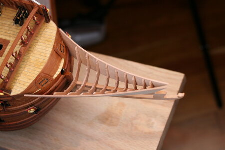
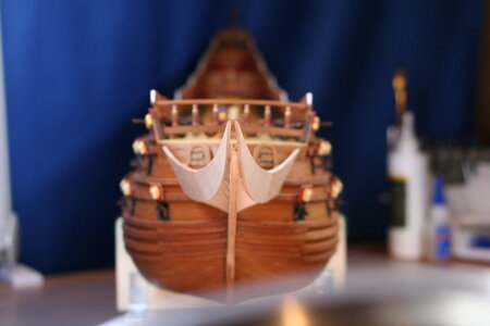
Vasa - 1:65 DeAgostini [COMPLETED BUILD]

Paul, for a future built. An idea.

Bent 2 thinner strips of wood nearby the center (easier to bent there than trying to bent near the tip). Take the bent to the desired curvature. Cut the excess from one side. The other side will be straight. Then you can complete the straight section of the rail. A little sanding and no one will see the joint.

I wrote 2 pieces of wood. You glue one over the other to get the final rail thickness and the Grove. A soft hand sanding of one border will create the Grove when they are glued together.

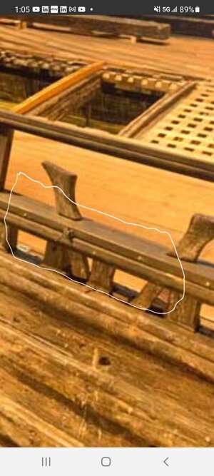
Just see what I tried to suggest on your Vasa museum pictures below.

The circle shows the joint. That was done on the original, at the museum, with another purpose. But give you the idea of the curve plus a straight section.
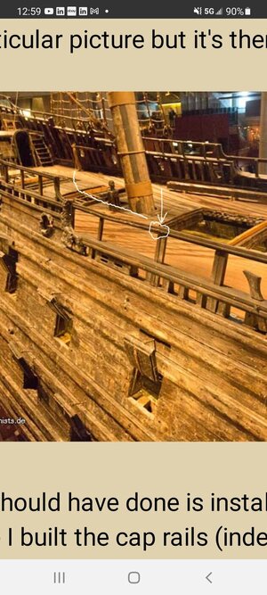
Screenshot_20210923-125946_Chrome.jpg

Here you have the 2 wood strips

Screenshot_20210923-130529_Chrome.jpg


Cheers
Daniel
 
Paul, for a future built. An idea.

Bent 2 thinner strips of wood nearby the center (easier to bent there than trying to bent near the tip). Take the bent to the desired curvature. Cut the excess from one side. The other side will be straight. Then you can complete the straight section of the rail. A little sanding and no one will see the joint.

I wrote 2 pieces of wood. You glue one over the other to get the final rail thickness and the Grove. A soft hand sanding of one border will create the Grove when they are glued together.

Just see what I tried to suggest on your Vasa museum pictures below.

The circle shows the joint. That was done on the original, at the museum, with another purpose. But give you the idea of the curve plus a straight section.

View attachment 257734

Here you have the 2 wood strips

View attachment 257735


Cheers
Daniel

A fine idea Daniel. I wonder if what you have described is actually how that railing was fabricated in real life (two thinner boards)? I kind of doubt it because I don't see any gaps or connectors on the museum ship rails. On the model it may be that thinner material could have withstood the tight radius needed in the curved section. Your solution would have made for a cleaner and more precise installation.

I think Billings provides these upper railings as laser cut plywood with the posts already cut to the proper length and with simulated curved sections. I don't recall how Corel handles this section (anyone?). DeAg just ignores the curved pieces and leaves the rail ending straight and level. This makes for a very clean installation but for me the curved railing was too distinctive to ignore. Of course I also need to turn everything into pear so I needed to scratch mine into existence.
 
Paul this is a GREAT looking ship!

To throw in another idea for the curved portion of the railings: each one looks to be 90 degrees of a circle. Would it be possible to make a full 360 degree circle the cut it 4 ways? I think it would be possible on a lathe if one had the skill (ever see a watchmaker on a lathe?).

Keep up the terrific work!
Glenn
Hello Glenn,

Welcome to my build log. I actually tried your idea - not using a lathe but I have lots of pear rods of various dimensions pending my fabrication of masts and yards. It worked for a few of the curves but not for others because the rise and run wasn't carefully configured ahead of time. That is, it would have worked if I hadn't already cut the straight portions before making the curves. Does that make sense?
 
Hello Friends,

One of the tasks I have been secretly dreading is the construction of the beakhead/galleon. I say that because it had become clear to me (for a variety of reasons) that I would not be able to use the kit supplied parts. Of course, this was not the first time I have made that decision, but the beakhead was going to present a much more significant challenge compared to other departures. Indeed, this was the first time I would need to rely on drawings in order to fabricate the components needed.

First I should mention that the kit did not come with any drawings - but I do have some 'big picture' drawings from the Vasamuseet (along with a copy of Landstrom). I also reached out to @Thomas Marocke who I have noticed seems to have access to all kinds of surprising resources. Well, it turns out he (once again) did, so I would like to publicly thank him for his help in this regard (though I suspect he would rather not be associated with my clumsy attempts at scratch building ;) ).

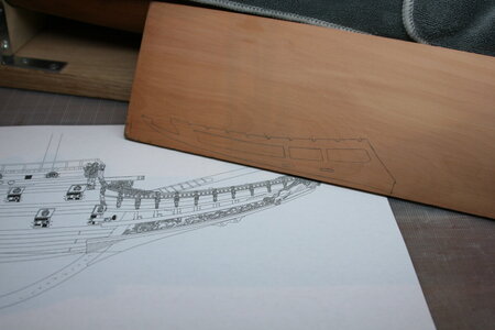
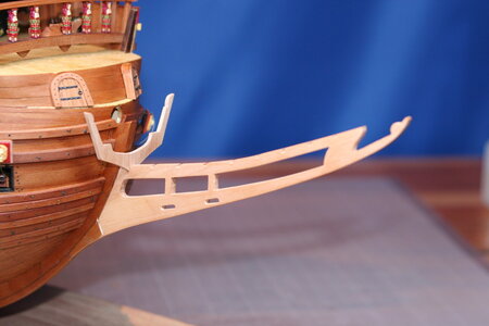
I started with the centerline:

IMG_7162.JPG

IMG_7169.JPG

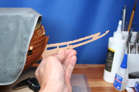
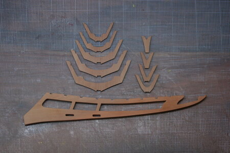
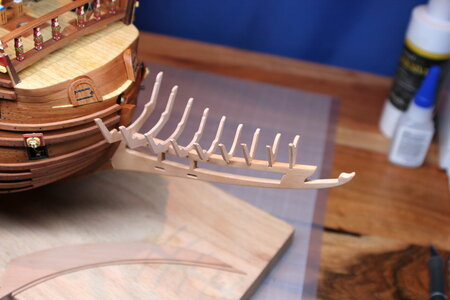
Oh, I forgot to mention that I bought myself a new toy: my very own green and yellow scroll saw! I not only used it to make the part above but also these frames:

IMG_7171.JPG

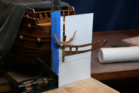
Next up was mounting the frames. The interface was delicate and I suspect there is a proper way to do this but I simply created a grid to control the port/starboard levels (and I used some framing square type things to ensure that the frames were 90 degrees to the centerline and perfectly vertical (well, approximately vertical)).

IMG_7174.JPG

IMG_7175.JPG

IMG_7178.JPG

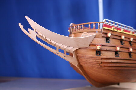
After carefully fairing the frames the next step was to add bulwark panels (obviously these were not a panel on the ship but would have been planks - but the bulwark will be painted and then festooned with castings of Roman emperors which will end up covering much of the surface so I chose to keep this part simple). But even more importantly, my frames needed stabilizing and they needed stabilizing FAST (they likely would not have survived the planking process the way I had things configured).

IMG_7180.JPG

IMG_7181.JPG

IMG_7182.JPG

IMG_7185.JPG

My plan is to add knees to the centerline and a few other details on the underside of the beakhead next. After that I will move to the top side...

Thank you for stopping by. I welcome your suggestions for how I can improve what you see here or any other aspect of my build.
 
Last edited:
Hello Friends,

One of the tasks I have been secretly dreading is the construction of the beakhead/galleon. I say that because it had become clear to me (for a variety of reasons) that I would not be able to use the kit supplied parts. Of course, this was not the first time I have made that decision, but the beakhead was going to present a much more significant challenge compared to other departures. Indeed, this was the first time I would need to rely on drawings in order to fabricate the components needed.

First I should mention that the kit did not come with any drawings - but I do have some 'big picture' drawings from the Vasamuseet (along with a copy of Landstrom). I also reached out to @Thomas Marocke who I have noticed seems to have access to all kinds of surprising resources. Well, it turns out he (once again) did, so I would like to publicly thank him for his help in this regard (though I suspect he would rather not be associated with my clumsy attempts at scratch building ;) ).

I started with the centerline:

View attachment 258827

View attachment 258828

Oh, I forgot to mention that I bought myself a new toy: my very own green and yellow scroll saw! I not only used it to make the part above but also these frames:

View attachment 258829

Next up was mounting the frames. The interface was delicate and I suspect there is a proper way to do this but I simply created a grid to control the port/starboard levels (and I used some framing square type things to assure that the frames were 90 degrees to the centerline and perfectly vertical (well, approximately vertical)).

View attachment 258830

View attachment 258831

View attachment 258832

After carefully fairing the frames the next step was to add bulwark panels (obviously these were not a panel on the ship but would have been planks - but the bulwark will be painted and then festooned with castings of Roman emperors which will end up covering much of the surface so I chose to keep this part simple). But even more importantly, my frames needed stabilizing and they needed stabilizing FAST (they likely would not have survived the planking process the way I had things configured).

View attachment 258833

View attachment 258834

View attachment 258835

View attachment 258836

My plan is to add knees to the centerline and a few other details on the underside of the beakhead next. After that I will move to the top side...

Thank you for stopping by. I welcome your suggestions for how I can improve what you see here or any other aspect of my build.
Looks great Paul! Excellent work with the scroll saw.
You can always add some thin veneer boards to the bulwark panels to represent individual planks.
 
Hello Friends,

One of the tasks I have been secretly dreading is the construction of the beakhead/galleon. I say that because it had become clear to me (for a variety of reasons) that I would not be able to use the kit supplied parts. Of course, this was not the first time I have made that decision, but the beakhead was going to present a much more significant challenge compared to other departures. Indeed, this was the first time I would need to rely on drawings in order to fabricate the components needed.

First I should mention that the kit did not come with any drawings - but I do have some 'big picture' drawings from the Vasamuseet (along with a copy of Landstrom). I also reached out to @Thomas Marocke who I have noticed seems to have access to all kinds of surprising resources. Well, it turns out he (once again) did, so I would like to publicly thank him for his help in this regard (though I suspect he would rather not be associated with my clumsy attempts at scratch building ;) ).

I started with the centerline:

View attachment 258827

View attachment 258828

Oh, I forgot to mention that I bought myself a new toy: my very own green and yellow scroll saw! I not only used it to make the part above but also these frames:

View attachment 258829

Next up was mounting the frames. The interface was delicate and I suspect there is a proper way to do this but I simply created a grid to control the port/starboard levels (and I used some framing square type things to assure that the frames were 90 degrees to the centerline and perfectly vertical (well, approximately vertical)).

View attachment 258830

View attachment 258831

View attachment 258832

After carefully fairing the frames the next step was to add bulwark panels (obviously these were not a panel on the ship but would have been planks - but the bulwark will be painted and then festooned with castings of Roman emperors which will end up covering much of the surface so I chose to keep this part simple). But even more importantly, my frames needed stabilizing and they needed stabilizing FAST (they likely would not have survived the planking process the way I had things configured).

View attachment 258833

View attachment 258834

View attachment 258835

View attachment 258836

My plan is to add knees to the centerline and a few other details on the underside of the beakhead next. After that I will move to the top side...

Thank you for stopping by. I welcome your suggestions for how I can improve what you see here or any other aspect of my build.
Absolutely splendid
 
Wow! I am surprised and delighted by your positive comments and likes! Thank you so much! Honestly, I spent more time trying to understand plans and thinking about how to do these parts than actually making them (though making them was also noteworthy for its consumption of time ;) ).

@Dean62 - I may do that very thing Dean - at least on the inboard side. I haven't quite sorted out what I'm doing there yet. The 'floor' is devilishly intricate so that whole area will take more thought.

@PeterG - fair question Peter. The short answer is plywood. While the laser cutting is fantastically accurate it is always done in pieces of ply and the orientation of the parts of the beakhead would mean the 'edge' of the ply would be most visible. As I have mentioned before the DeAg solution is to paint everything. Please don't think that I am bashing the DeAg kit (bashing in the traditional sense not as used among ship modelers). This kit is wonderful and would build into a very nice model of the Vasa (indeed, there are countless examples on the forums). I would commend it to anyone - especially to someone just getting started in the hobby as the simplified design is very buildable.

I should add that when I made the decision to forego the use of ply long ago I did not fully grasp the consequences of that seemingly benign decision. Perhaps in retrospect I should have just built the kit the way it was intended and saved myself the trouble. Then again, I truly enjoy puzzling out how to do something as much as the doing. It may be that the problem lies inside of me rather than in the kit.

Again, I am grateful to everyone who has continued to encourage me along the way. And I equally welcome your suggestions for improvement- it takes a village...
 
Last edited:
Perhaps in retrospect I should have just built the kit the way it was intended and saved myself the trouble. Then again, I truly enjoy puzzling out how to do something as much as the doing. It may be that the problem lies inside of me rather than in the kit.

Again, I am grateful to everyone who has continued to encourage me along the way. And I equally welcome your suggestions for improvement- it takes a village...
Paul, you're doing this right. It is correct that they decided to change something in the kit. This is exactly what happens to develop a ship modeler. Just assembling the kit according to the instructions is one thing. When you begin to delve into the intricacies of shipbuilding of those times, the arrangement of ships, their equipment and equipment, you will understand that everything in the set is not so perfect. There is a desire to change something. And the further you do it, the more this desire to make changes. One of my acquaintances, a modeler, says that in the set the maximum that should remain is a skeleton (keel frame and frames). The rest needs to be redone. Everyone has their own goals in the alteration, someone does not like the disagreement with the historical period, someone wants to improve the external perception of the model by using different woods instead of paints. There are many ways of development in the kits.
But I warn you, once you have embarked on this path, you will no longer be able to stop. And when you achieve mastery in this, you need a transition to a new stage - making models according to drawings. As we say - building with "0". It's my opinion.
So Paul, I fully support you in making changes and improvements to the set.
 
Outstanding job Paul. Joy to watch it. Just wondering what happened to "The intricacy of these parts has me just about convinced that scratch building is not in my future." I'm afraid, you went on the other side. Thank you for this lovely, educational build log.
 
“It may be that the problem lies inside of me rather than in the kit.”

This really made me laugh! Paul, your consistent excellence at first-attempts is becoming - dare I say it?

Predictable.

But, this is a good problem to have. I’m sure you’ll really mess up, somewhere along the way, but the way out of those mistakes makes for some of the best blog reading.

I can appreciate the head-scratching, in this very complicated area, as I will soon have to pattern new head rails for the SR. There’s lots to consider, but you aced through that one with a triple-barrel roll!

If you do decide to plank the beakhead sides, Vasa has some interesting timbering for those sides that appear to follow the builders’ best practice of leaving nothing to waste.
 
Paul, you're doing this right.
Much appreciated Sasha. In many ways I have accidently stumbled half the way toward your colleague's advice. My model still retains the infrastructure from the kit but most of what you see has been modified (sometimes just a bit and others times completely redesigned). This approach does make it fun because I don't have to completely understand ship construction and focus more on the aesthetic.

Outstanding job Paul. Joy to watch it. Just wondering what happened to "The intricacy of these parts has me just about convinced that scratch building is not in my future." I'm afraid, you went on the other side. Thank you for this lovely, educational build log.
Purely accidental deviation! I'm already regretting it.

“It may be that the problem lies inside of me rather than in the kit.”

This really made me laugh! Paul, your consistent excellence at first-attempts is becoming - dare I say it?

Predictable.

But, this is a good problem to have. I’m sure you’ll really mess up, somewhere along the way, but the way out of those mistakes makes for some of the best blog reading.

I can appreciate the head-scratching, in this very complicated area, as I will soon have to pattern new head rails for the SR. There’s lots to consider, but you aced through that one with a triple-barrel roll!

If you do decide to plank the beakhead sides, Vasa has some interesting timbering for those sides that appear to follow the builders’ best practice of leaving nothing to waste.
Yes, I have that drawing and it is truly a hodgepodge. I'm looking forward to my next epic mess-up if for no other reason than to add interest to my build log ROTF !!!
 
Last edited:
Back
Top