Great research Peter, I did not realize there was such a knock off problem in terms of quality. I would have just assumed that some brands were better than others in terms of authenticity and quality. At any rate I'm happy to hear you had a great birthday vacation celebration and will be looking forward to watching your next build. In the meantime, keep those wonderful Vasa pictures coming!On my return from the birthday treat, I have gotten back into a bit more rigging. I am working on the spritsail and finishing the mizzen but in the background, the thought has occurred to me that I do not have too much longer to finish this ship. Obviously, there is still a lot to do and it will take a couple of months, but the end is distantly in sight. So, I thought, "What next???" As it happens, a few years ago during a trip to England (when travel was unencumbered by Covid etc), my wife and I visited HMS Victory in Portsmouth. As my experience in modelling the Vasa has been underpinned by the amount of research and acquired information about the ship (from the Vasamuseet, research papers etc etc), and with the HMS Victory, similar research was existing, and so it seemed like a logical choice.
I think I am reasonably committed now to it's being my next venture and so I started to do some research of the ship and available kits. If you trawl through the various Build Logs with a 'Victory' keyword search there are a huge number of modeller's been down this route. There is also some excellent background research and descriptive build books available. The one thing that stood out as possibly the 'best' and most complete Victory model on offer today, is the Caldercraft (JoTika) HMS Victory, made in Britain but incredibly difficult get get hold of at the moment. Most distributors are out of stock and while this is probably only a temporary thing, at the moment, it is difficult, and expensive - We are talking about a big model and a price tag to match.
One thing however which came out of this research of a new kit that I was not fully aware of, is the marketing and availability of model kit 'copies' or 'knock-offs'. Call me "naive" to the bad ways of the world!! In particular, I became aware of some companies promoting model kits (including the HMS Victory), which are referred to as 'knock-offs' and which clearly are direct copies of existing and well regarded model kit manufacturer's products. This is a huge problem for the model ship manufacturers, to have their design work effectively 'stolen' and then marketed to unsuspecting modellers who are not aware they are buying a considerably cheaper copy of a legitimate ship kit.
Evidence of this practice led me to an especially good article on the NRG (Nautical Research Guild) website here "https://thenrg.org/resource/articles/anatomy-of-a-knock-off" by Chris Coyle and James Hatch. I would urge all those thinking of purchasing one of these (especially Chinese) kits to read this article - It is most convincing and inarguable as to the piracy that is being committed. In particular, one of the companies named in this article (and there are similar discussions on MSW, where certain manufacturer kit build logs are banned), was the ZHL model of HMS Victory. It is about half the cost of the Caldercraft model kit and would be very tempting for many modellers.
In my research of the ZHL Model website, interestingly, I was amazed to see that the FIRST thing you see when you open the website, is a US Trade and Patent certificate issued by the US Patent and Trademark Office. If you do a search of the company and registration number, sure enough, this is a valid trademark issued by the US - How can that be when their products are clearly knock-offs??
View attachment 302909
Delving further into their website, I was intrigued at one associated article in their Forum which detailed a Build Log of their model of the Flying Dutchman. This fictitious ship has been modelled and detailed as an available kit but as you go through the Build Log (link is here). A picture of the hull being built is below. Does this look familiar?????
View attachment 302910
View attachment 302915
On going through the Build Log further, I then found references to the original Vasamuseet Vasa ship plans, and these were shown:
View attachment 302911
So the Vasa, has been used as the basis for the design and building of this Flying Dutchman ship. Very interesting. An additional link for this is here. Note too that (I don't know where in the world), but there is a full size replica of the Flying Dutchman and this is referred to extensively on the website.
View attachment 302912
This is all just a NEW and parallel universe to me. It makes for interesting, but almost scary corruption of a seemingly benign hobby industry relating to model ship building!! It is NOT an industry or aspect to the industry which should be sought out or bought from, in my opinion.
Regards,
PeterG
You are using an out of date browser. It may not display this or other websites correctly.
You should upgrade or use an alternative browser.
You should upgrade or use an alternative browser.
Vasa Build Log - Billing Boats - Scale 1/75 [COMPLETED BUILD]
Not sure what constitutes a knock off. There are differences in the kits for ZHL and Mantua. et al. Just because I create a model of the Blue Nose II and someone else uses some of the same ideas I did and makes it more cheaply, doesn't make it a knock off. Some of those ideas just go with the original plans or lines or historical pictures of the actual ship. I guess that makes us all knock-off artists of the original. Some of us are better at it than others. The picture of the Flying Dutchman above does have some striking similarities in the gallery to the Vasa. Does that make this imaginary ship a knock off? And then there's the infamous Black Pearl by ZHL and the true knock offs of the ZHL models. Those are models sold as complete kits that are not complete and have cheap parts copied directly from the ZHL models. I'm not judging at this time. I do try to go for the best value for the money. But I strive to do nothing unethical or illegal. But then again, I don't boycott a certain brand of ketchup just because the husband of the heiress to the fortune is a political hack whose brand of politics I abhor. (Especially if I like the ketchup.) Sorry for the rambling, Peter. But you brought it on yourself by bringing it up.On my return from the birthday treat, I have gotten back into a bit more rigging. I am working on the spritsail and finishing the mizzen but in the background, the thought has occurred to me that I do not have too much longer to finish this ship. Obviously, there is still a lot to do and it will take a couple of months, but the end is distantly in sight. So, I thought, "What next???" As it happens, a few years ago during a trip to England (when travel was unencumbered by Covid etc), my wife and I visited HMS Victory in Portsmouth. As my experience in modelling the Vasa has been underpinned by the amount of research and acquired information about the ship (from the Vasamuseet, research papers etc etc), and with the HMS Victory, similar research was existing, and so it seemed like a logical choice.
I think I am reasonably committed now to it's being my next venture and so I started to do some research of the ship and available kits. If you trawl through the various Build Logs with a 'Victory' keyword search there are a huge number of modeller's been down this route. There is also some excellent background research and descriptive build books available. The one thing that stood out as possibly the 'best' and most complete Victory model on offer today, is the Caldercraft (JoTika) HMS Victory, made in Britain but incredibly difficult get get hold of at the moment. Most distributors are out of stock and while this is probably only a temporary thing, at the moment, it is difficult, and expensive - We are talking about a big model and a price tag to match.
One thing however which came out of this research of a new kit that I was not fully aware of, is the marketing and availability of model kit 'copies' or 'knock-offs'. Call me "naive" to the bad ways of the world!! In particular, I became aware of some companies promoting model kits (including the HMS Victory), which are referred to as 'knock-offs' and which clearly are direct copies of existing and well regarded model kit manufacturer's products. This is a huge problem for the model ship manufacturers, to have their design work effectively 'stolen' and then marketed to unsuspecting modellers who are not aware they are buying a considerably cheaper copy of a legitimate ship kit.
Evidence of this practice led me to an especially good article on the NRG (Nautical Research Guild) website here "https://thenrg.org/resource/articles/anatomy-of-a-knock-off" by Chris Coyle and James Hatch. I would urge all those thinking of purchasing one of these (especially Chinese) kits to read this article - It is most convincing and inarguable as to the piracy that is being committed. In particular, one of the companies named in this article (and there are similar discussions on MSW, where certain manufacturer kit build logs are banned), was the ZHL model of HMS Victory. It is about half the cost of the Caldercraft model kit and would be very tempting for many modellers.
In my research of the ZHL Model website, interestingly, I was amazed to see that the FIRST thing you see when you open the website, is a US Trade and Patent certificate issued by the US Patent and Trademark Office. If you do a search of the company and registration number, sure enough, this is a valid trademark issued by the US - How can that be when their products are clearly knock-offs??
View attachment 302909
Delving further into their website, I was intrigued at one associated article in their Forum which detailed a Build Log of their model of the Flying Dutchman. This fictitious ship has been modelled and detailed as an available kit but as you go through the Build Log (link is here). A picture of the hull being built is below. Does this look familiar?????
View attachment 302910
View attachment 302915
On going through the Build Log further, I then found references to the original Vasamuseet Vasa ship plans, and these were shown:
View attachment 302911
So the Vasa, has been used as the basis for the design and building of this Flying Dutchman ship. Very interesting. An additional link for this is here. Note too that (I don't know where in the world), but there is a full size replica of the Flying Dutchman and this is referred to extensively on the website.
View attachment 302912
This is all just a NEW and parallel universe to me. It makes for interesting, but almost scary corruption of a seemingly benign hobby industry relating to model ship building!! It is NOT an industry or aspect to the industry which should be sought out or bought from, in my opinion.
Regards,
PeterG
Many thanks Grant for your comments. That is an excellent point you make about the Mantua Victory. I am certainly not intending to purchase too much additional material if I pursue the Caldercraft decision, so to have to then spend the additional money may well be worth it. I have never read a poor review about the Caldercraft kit, and I am starting to build quite a list.
The kit pirating issue concerns me. You are correct here too unfortunately - it does seem to be the way of the world, whether we are talking about real life cars, televisions or model ship kits. The latent disrespect for the work of others is what is so concerning. You only have to see the level of plagiarism in universities, schools and the ease to access to others work through the internet etc etc. Maybe we are just old school!!
The important thing I guess is that people be aware that this trade and knock-off kits are out there. It makes interesting reading to read the policies and views taken on this issue by the model ship building administrators of SOS and ModelShip World sites.
Thanks again Grant,
Regards,
PeterG
Last edited:
Thanks also to Daniel and Vfordyce. I am sure everyone will have an opinion on this pirating topic and it is always interesting to read other people’s points of view - after all, that’s what a Forum is for, as well as our Build Logs etc.
I guess it’s the lowering of standards and the adoption of a ‘cheap solution’ that worries me. Through my life, I have strived to achieve a level of attainable high quality and not a lowered standard because it Is easier or cheaper, but the world doesn’t always allow the higher standard when a cheaper, more practical lesser product will do the job. It’s why we put so much time and effort into our models, to make them the best we can, and to make them ‘stand out’ as being evidence of the detail and precision we can achieve for others to admire.
I appreciate your comments gentlemen,
Regards,
PeterG
Thanks for the thoughtful discussion, Peter.Thanks also to Daniel and Vfordyce. I am sure everyone will have an opinion on this pirating topic and it is always interesting to read other people’s points of view - after all, that’s what a Forum is for, as well as our Build Logs etc.
I guess it’s the lowering of standards and the adoption of a ‘cheap solution’ that worries me. Through my life, I have strived to achieve a level of attainable high quality and not a lowered standard because it Is easier or cheaper, but the world doesn’t always allow the higher standard when a cheaper, more practical lesser product will do the job. It’s why we put so much time and effort into our models, to make them the best we can, and to make them ‘stand out’ as being evidence of the detail and precision we can achieve for others to admire.
I appreciate your comments gentlemen,
Regards,
PeterG
Recently there was a discussion on mounting models using pedestals (link here). I have decided to use three brass pedestals to mount my Vasa. These pedestals I have had made (by a great friend of mine who has a great array of workshop tools including lathes and milling machines). He produced for me (for a bottle of good quality wine - Thank you Gary), a shortened brass set of pedestals which were drilled and tapped and have a hole in the top allowing a secure screw into the keel of the ship along its base. The slot in the top of the pedestal allows the keel to slot into place securely and the internal screw holds it in place. The second pedestal in the picture below shows the depth of the screw I have used. AT the base of the pedestal is a 1/4" hole with treaded machine tap to allow the three pedestals to be secured to a base of timber.
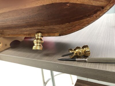
The base timber I have not obtained yet and I am wondering whether to to go with a single wide board (maybe cedar or Australian hardwood) or a series of thinner boards (like butting floor board hardwood). The timber base would then be cut an appropriate size and a rectangle groove routed to receive a Perspex enclosed case for the ship. I won't have a lot of clearance for the case around the ship (about 1 cm at the top main mast) and so the pedestals had to be relatively short. They seem very strong however and hold the ship well both horizontally and laterally.
In reality, I should have given this aspect of mounting the ship more thought much earlier in the build. To drill and fit the holes/threads into the ship etc at this late stage with rigging/masts etc is fraught with danger. Had I thought about it earlier, I would have predrilled the keel almost at the outset while fitting bulkheads and then installed threaded tube with side strengthening to provide more solid support (some advice for future builders).
Regards,
PeterG
A bit more on the rigging. As I discussed earlier, I needed a bunch more blocks. To obtain the better quality and shaped blocks commercially available from some of the vendors of North America or Europe, takes a long time in Australia. so, I decided to pursue what was available and then re-shape the blocks myself. I bought some Artesania Latina and Occre block packs from a local hobby store and these arrived after only 2-3 days. Below is the processing I applied to make them suitable for my application. I have purchased 4mm and 6mm blocks. After rubbing/sandpapering and re-shaping, they end up about 3mm and 4mm respectively.
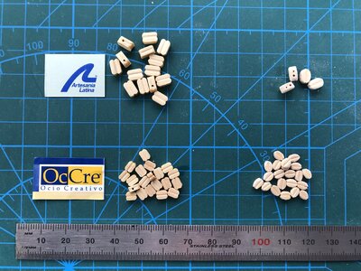
In the above picture, the as supplied blocks are on the left and the reworked blocks are on the right. Obviously the reshaping is done individually and it's tough on the fingers. I tend to use the nailfile type of sandpaper rather than paper sanding paper as it gives better control and they come with a rough and smooth sanding side. Once sanded to the shape required, I then drill a second hole for lines to pass through (as you can see in the top blocks) and then using a small drill mounted router (from a dentist supply shop), I ream out a small groove between the two holes to simulate the rope groove on 'real' blocks.
I have built a small rotating drum which is internally lined with sandpaper and the near-finished blocks go in to this with some round wooden balls (beads) that smooth and apply a finish to the sanded blocks that is then ready for staining. The final stage is to stain the blocks which I do with a dark brown that makes the final blocks match those already on the ship.
I have been surprised how many more blocks I have required over and above those supplied with the Billings Boat kit. I am up to about 100 more blocks than initially supplied. When working on the running rigging, you tend to use an awful lot, and while the kit supplied blocks would be adequate for a basically rigged configuration, I have insisted on things like bowlines and clewlines even for spars that are not carrying sails (the majority). This has used up a lot of additional blocks, but it is more accurate and I think in keeping with a ship that would be sailed without these sails set.
Regards,
PeterG.
A bit on the rigging of the spritsail and sprit topsail. I have examined a range of sail plans relating to this area at the bow of the ship and referred to references like Anderson etc. As I have decided to only have the five sails set (as per the pictures/videos of the ship at the time of her sinking), this means that these spars had to be rigged without sails even 'hanked' and furled on. The usual spar running rigging was OK to fix (such as the lifts, halyards etc. However the running rigging used for the sails when they are set upon the spars are a different matter. In all the rigging plans I have studied, these detail the running rigging WITH the sails set. So, what happens to these lines when the sails are NOT set? Lines such as the braces, clews, tacks and sheets can be reasonably mounted and tensioned, even though unattached to the corner points of the sail (as they attach to each other or the spar itself). However lines such as the bowlines, leechlines and buntlines are a problem, as they have securing points on the sail itself with no other support lines at their ends.
My approach was to fit the 'trouble' lines as if I were a crew member, and where I would logically go to get these ropes and their attachment points when I was about to mount a sail. In most cases this seemed to be the spar itself or to an attachment line that was the control going back to a belaying point (as documented in the Belaying Plans). The result is as below:
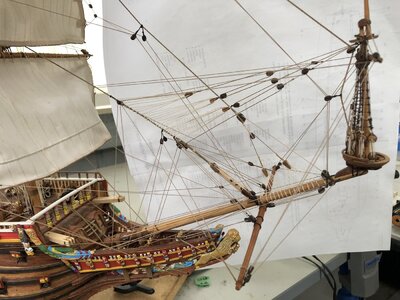
From the picture you can see (especially at the ends o the spritsail spar), the clew, sheet and tack with braces going to blocks mounted on the bowsprit. The spritsail yard does not have a parrel/truck arrangement, but was designed to move forward and aft (a small distance) along the bowsprit by the use of a 'strop' which when released could be pulled by a block/tackle mounted parallel with the bowsprit and the forward block attached just aft of the bowsprit head.
For the spritsail topsail spar, there is a two-hole parrel wrapping around the spritsail mast to allow it to be raised and lowered. I know that I have made a fundamental error in most of my spars where the sails have not been mounted. On 'real' ships, usually the spars are lowered to their lowest point when not carrying sails and for ease of attaching the sails. After the sail is attached, the spar is raised (with the sail being set or furled) to its upper position. My mounting of the spars in their upper positions therefore is an error, but to me, it's one worth adopting as it makes the entire rig look more balanced. I am also mindful that if I were to mount them in their lowered positions (with no sails attached), I would be forever explaining to people who view my model, as to why this was so.
Considerable use is made of the foremast and fore topsail stays to secure aft lines for the braces and lifts of the spritsail. Below is a downward-looking view of the lines.
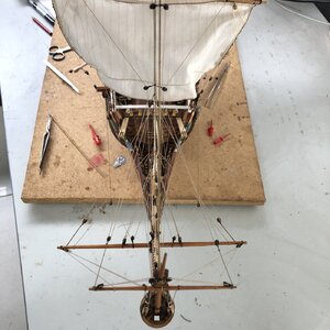
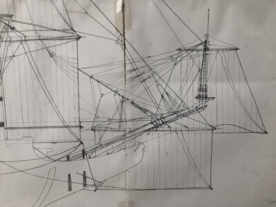
It's a complex arrangement and I have primarily used the Vasamuseet plans to rig the lines. Amazingly the lines don't seem to foul each other and the support of the spars is very strong. The relevant museum plans are shown below:
Regards
PeterG
My approach was to fit the 'trouble' lines as if I were a crew member, and where I would logically go to get these ropes and their attachment points when I was about to mount a sail. In most cases this seemed to be the spar itself or to an attachment line that was the control going back to a belaying point (as documented in the Belaying Plans). The result is as below:

From the picture you can see (especially at the ends o the spritsail spar), the clew, sheet and tack with braces going to blocks mounted on the bowsprit. The spritsail yard does not have a parrel/truck arrangement, but was designed to move forward and aft (a small distance) along the bowsprit by the use of a 'strop' which when released could be pulled by a block/tackle mounted parallel with the bowsprit and the forward block attached just aft of the bowsprit head.
For the spritsail topsail spar, there is a two-hole parrel wrapping around the spritsail mast to allow it to be raised and lowered. I know that I have made a fundamental error in most of my spars where the sails have not been mounted. On 'real' ships, usually the spars are lowered to their lowest point when not carrying sails and for ease of attaching the sails. After the sail is attached, the spar is raised (with the sail being set or furled) to its upper position. My mounting of the spars in their upper positions therefore is an error, but to me, it's one worth adopting as it makes the entire rig look more balanced. I am also mindful that if I were to mount them in their lowered positions (with no sails attached), I would be forever explaining to people who view my model, as to why this was so.
Considerable use is made of the foremast and fore topsail stays to secure aft lines for the braces and lifts of the spritsail. Below is a downward-looking view of the lines.

It's a complex arrangement and I have primarily used the Vasamuseet plans to rig the lines. Amazingly the lines don't seem to foul each other and the support of the spars is very strong. The relevant museum plans are shown below:

Regards
PeterG
Last edited:
The mizzen running rigging has now been completed as has the crojack and mizzen topsail spar. The mizzen sail has a complicated brace arrangement just aft of the mainmast, allowing for starboard or port adjustment to optimise the wind angle. Below is a picture of the mizzen deck areaand the forward mizzen spar braces:
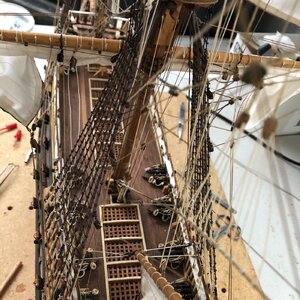
You can also see the various belaying points on the railings for the upper mainmast and topgallant lines. Looking down the stay that runs from the base of the mainmast to the mizzen top, I found it almost impossible to keep this line straight, with the crowsfeet and other lines attached. It is not so noticeable from the side view of the ship but if I were to apply any greater tension to straighten it, I think there may have been consequences relating to the mast rake angle.
Another rear port side picture of the ship shows the various lines attached to the mizzen sail, including brails and top rope attached and controlling the parrels and trucks used to attach the mizzen spar to the mast.
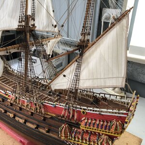
The aft leechline and lift of the mizzen sail and spar can also been seen. I used a double block sheet arrangement to an eyebolt in the deck for the rear of the sail and a similar double block and hook for the forward bonnet downhaul of the mizzen sail (as opposed to the forward mizzen spar brace that is mounted to the main stays through two blocks mounted at the front of the mizzen spar).
Regards
PeterG.

You can also see the various belaying points on the railings for the upper mainmast and topgallant lines. Looking down the stay that runs from the base of the mainmast to the mizzen top, I found it almost impossible to keep this line straight, with the crowsfeet and other lines attached. It is not so noticeable from the side view of the ship but if I were to apply any greater tension to straighten it, I think there may have been consequences relating to the mast rake angle.
Another rear port side picture of the ship shows the various lines attached to the mizzen sail, including brails and top rope attached and controlling the parrels and trucks used to attach the mizzen spar to the mast.

The aft leechline and lift of the mizzen sail and spar can also been seen. I used a double block sheet arrangement to an eyebolt in the deck for the rear of the sail and a similar double block and hook for the forward bonnet downhaul of the mizzen sail (as opposed to the forward mizzen spar brace that is mounted to the main stays through two blocks mounted at the front of the mizzen spar).
Regards
PeterG.
With the running rigging nearly complete, I have made the decision that now would be a good time to mount the upper railings. These railings are supplied with the kit as a series of thin plywood cutouts and no instruction as to how they should be mounted. They are very flimsy and because the ply is so thin, they can break easily. I cannot imagine having to do the running rigging with these in place as it would have been a nightmare to insert the belaying points and pins through the lower railing. Below is a picture of one of the railing that I have used a set of vertically inserted brass wires and appropriately positioned holes drilled along the lower railing.
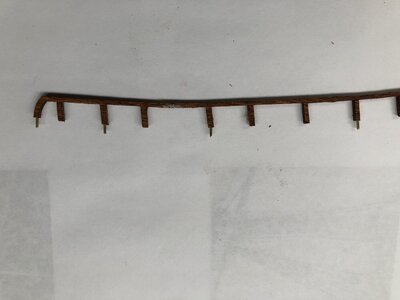
With the rigging in place, I was able to carefully insert the railing pieces at their appropriate locations, and then line up the predrilled brass wire inserts. The drilling and positioning of the railings was done soon after the masts were mounted but before installing the mast stays or any other rigging. It was fortunate that I thought of this as it would have been impossible to drill the necessary wire holes with the standing and running rigging in place.
Below you can see some of the railings in place amidships:
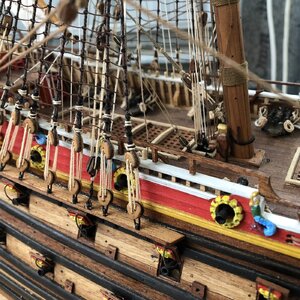
When added to the entire ship, these rails look quite good and the wire inserts are hidden within the lower, white railing. When I decided to use this white railing for my belaying pins too, I drilled their holes, not in the centre, but towards the inboard half of the width of the railing. This allowed for the lines attached to the pins, to not interfere with the upper railing and for pins to be removed as the crewmen would have to from time to time.
Regards,
PeterG.

With the rigging in place, I was able to carefully insert the railing pieces at their appropriate locations, and then line up the predrilled brass wire inserts. The drilling and positioning of the railings was done soon after the masts were mounted but before installing the mast stays or any other rigging. It was fortunate that I thought of this as it would have been impossible to drill the necessary wire holes with the standing and running rigging in place.
Below you can see some of the railings in place amidships:

When added to the entire ship, these rails look quite good and the wire inserts are hidden within the lower, white railing. When I decided to use this white railing for my belaying pins too, I drilled their holes, not in the centre, but towards the inboard half of the width of the railing. This allowed for the lines attached to the pins, to not interfere with the upper railing and for pins to be removed as the crewmen would have to from time to time.
Regards,
PeterG.
- Joined
- Aug 30, 2020
- Messages
- 639
- Points
- 308

Nice job, it looks time consuming and fiddly but has now made me think about the blocks I have if they need a bit of customising.A bit more on the rigging. As I discussed earlier, I needed a bunch more blocks. To obtain the better quality and shaped blocks commercially available from some of the vendors of North America or Europe, takes a long time in Australia. so, I decided to pursue what was available and then re-shape the blocks myself. I bought some Artesania Latina and Occre block packs from a local hobby store and these arrived after only 2-3 days. Below is the processing I applied to make them suitable for my application. I have purchased 4mm and 6mm blocks. After rubbing/sandpapering and re-shaping, they end up about 3mm and 4mm respectively.
View attachment 305675
In the above picture, the as supplied blocks are on the left and the reworked blocks are on the right. Obviously the reshaping is done individually and it's tough on the fingers. I tend to use the nailfile type of sandpaper rather than paper sanding paper as it gives better control and they come with a rough and smooth sanding side. Once sanded to the shape required, I then drill a second hole for lines to pass through (as you can see in the top blocks) and then using a small drill mounted router (from a dentist supply shop), I ream out a small groove between the two holes to simulate the rope groove on 'real' blocks.
I have built a small rotating drum which is internally lined with sandpaper and the near-finished blocks go in to this with some round wooden balls (beads) that smooth and apply a finish to the sanded blocks that is then ready for staining. The final stage is to stain the blocks which I do with a dark brown that makes the final blocks match those already on the ship.
I have been surprised how many more blocks I have required over and above those supplied with the Billings Boat kit. I am up to about 100 more blocks than initially supplied. When working on the running rigging, you tend to use an awful lot, and while the kit supplied blocks would be adequate for a basically rigged configuration, I have insisted on things like bowlines and clewlines even for spars that are not carrying sails (the majority). This has used up a lot of additional blocks, but it is more accurate and I think in keeping with a ship that would be sailed without these sails set.
Regards,
PeterG.
Good day Peter,
Very accurate and clean rigging works - I like it!
It is sad You decided don't show full set of sails( I saw you remarks why not), but even than ,it looks very good!!!
Thanks for share with us.
All the best!
Kirill
Very accurate and clean rigging works - I like it!
It is sad You decided don't show full set of sails( I saw you remarks why not), but even than ,it looks very good!!!
Thanks for share with us.
All the best!
Kirill
Good morning Peter. Complex rigging done really well- great job. The number of blocks and lines is like getting “lost in translation “. Your rail fitting was “just in time”. I must admit I would have fitted this way earlier however I do see your logic for waiting a tad. Looking very good all round. Cheers GrantWith the running rigging nearly complete, I have made the decision that now would be a good time to mount the upper railings. These railings are supplied with the kit as a series of thin plywood cutouts and no instruction as to how they should be mounted. They are very flimsy and because the ply is so thin, they can break easily. I cannot imagine having to do the running rigging with these in place as it would have been a nightmare to insert the belaying points and pins through the lower railing. Below is a picture of one of the railing that I have used a set of vertically inserted brass wires and appropriately positioned holes drilled along the lower railing.
View attachment 305683
With the rigging in place, I was able to carefully insert the railing pieces at their appropriate locations, and then line up the predrilled brass wire inserts. The drilling and positioning of the railings was done soon after the masts were mounted but before installing the mast stays or any other rigging. It was fortunate that I thought of this as it would have been impossible to drill the necessary wire holes with the standing and running rigging in place.
Below you can see some of the railings in place amidships:
View attachment 305684
When added to the entire ship, these rails look quite good and the wire inserts are hidden within the lower, white railing. When I decided to use this white railing for my belaying pins too, I drilled their holes, not in the centre, but towards the inboard half of the width of the railing. This allowed for the lines attached to the pins, to not interfere with the upper railing and for pins to be removed as the crewmen would have to from time to time.
Regards,
PeterG.
Hello Peter,
This is a great update. I am in awe of your rigging and your complex commentary. The crow's feet are outstanding, I know now how difficult they are as I have installed the first set myself. Since I have already installed my top rail, I may be swimming in a bucket of tears trying to belay all the running rigging, we shall see.
Long reach tweezers and patients seems to be the key. Again, wonderful presentation and results!
As always, Peter, your posts are loaded with great information and outstanding execution. Sadly, much of your narrative is so far out of my depth that it induces more fear than comfort - but it is also helping me make some decisions about my own rigging goals. Thank you for sharing your amazing work with us - this is an inspiring body of work and we are all blessed that you have shared your journey with us.
No it isn't. You understood perfectly that the features of having belaying pins BELOW the railings makes them hard to access and to use. You're just feeling angst because Peter made you aware of a dilemma you will face later in your build. To save yourself from self destruction of all your fragile confidence, you may want to refrain from reading any posts that are father ahead that your build steps. Or maybe you can tell yourself that you yourself have overcome so many much more sizeable dilemmas, to the admiration and astonishment of all your fellow forum members. You're a great builder, Paul, so Stop Whining.As always, Peter, your posts are loaded with great information and outstanding execution. Sadly, much of your narrative is so far out of my depth that it induces more fear than comfort - but it is also helping me make some decisions about my own rigging goals. Thank you for sharing your amazing work with us - this is an inspiring body of work and we are all blessed that you have shared your journey with us.

Take notes how Peter resolves the railing/belaying pin issue. You'll solve that issue soon yourself.
Let me guess... you thought your kit provided COMPLETE instructions?


 Both of us are WAYYYYY beyond that now!
Last edited:
Actually I was talking about the rigging details not the handrailsNo it isn't. You understood perfectly that the features of having belaying pins BELOW the railings makes them hard to access and to use. You're just feeling angst because Peter made you aware of a dilemma you will face later in your build. To save yourself from self destruction of all your fragile confidence, you may want to refrain from reading any posts that are father ahead that your build steps. Or maybe you can tell yourself that you yourself have overcome so many much more sizeable dilemmas, to the admiration and astonishment of all your fellow forum members. You're a great builder, Paul, so Stop Whining.
Take notes how Peter resolves the railing/belaying pin issue. You'll solve that issue soon yourself. Let me guess... you thought your kit provided COMPLETE instructions?
 .
.Oh.. Then resume collapsing into a puddle of jelly.Actually I was talking about the rigging details not the handrails.

Belay that! Watch how Peter solves his problems. You will no doubt have different ideas that you will use on your model, because even though we build the same ships, we often weigh the flotsam of research info (or lack of it) differently, and that's how features become different.

I have a huge problem deciding which version of a ship feature is the best one. It goes with the territory. Suffice to say, you'll solve all the rigging line issues one at a time like we all do. You just have to see it through. If you have trouble deciding how or where something goes, post it here. Someone like Uwe or Maarten of Hubac's Historian, all more experience than us two, will pipe up and though you some bit of information that will help you decide. I have a few tricks for pulling lines through those crowded holes in the tops that I could show you, because you can't push rope.
Last edited:
Many thanks to you all for your comments and support. The issue of the railings was one I thought about long and hard in terms of 'what is the best time to fit them'. My advice would be, fit them early but with an arrangement that allows them to be removed and refitted after the rigging and potential for damage is minimised.
Kurt (Darivs Architectvs) - I love the way your comments are 'blunt' (in Australia we would say 'You have no hesitation in calling a spade a shovel') - This means that your comments come right to the point and call out how it is. However, in the end, you are correct - Each rigging line has it's own decisions to be made as the documentation of all these older ships, is largely supposition based on accumulated knowledge and research from various sources of how things were done in the day (of 1629!!). Research and reading is the key.
My following post is an indication of this as it relates to some decisions to make about various rigging lines...
PeterG
I received a personal correspondence from Paul (Dockattner) regarding a rigging line which was a bit difficult to pin down and work out where it went, belaying point etc. The email trail went like this:
PAUL
Hi Peter,
If you don't mind fielding a question...for the bilateral mizzen stays...it looks like you took the tensioning rope to a hook on the deck (presumably attached to an eyebolt). Is that what you did? Others say the line goes to the 'pin rails' on the deck (which probably didn't exist) and I don't see a belay location for those lines on anyone's belay plans. Thanks for any guidance you can provide.
Paul
PETER RESPONDS
Hi Paul,
... In terms of the 'bilateral mizzen stays', I am not 100% sure I know which lines you are referring to.
So Paul sent a photo with an arrow indicating the line in question and the comment 'See below. Where does this line terminate (and how)? Thank you for taking the time to help me out!'
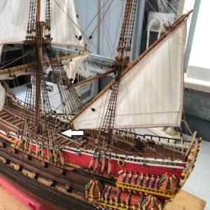
PETER RESPONDS
Hi Paul,
I thought I had picked the wrong line with what you described as 'bilateral mizzen stays'. The line you are pointing at is the Main Topsail Brace. This line is a complex bit of rigging and is best explained by the run of the rigging in the Vasamuseet plans which I show below.
The Vasamuseet plan for the Main Topsail Brace which I have highlighted, starts with a double secure point on the Mizzen mast just below the mizzen top but just above the Crojack spar. This ensures it will not foul the lower edge of the mizzen topsail when set. From this point, one line goes to the port and one to the starboard single blocks at the end of the Main Topsail pendants connected to this sail's spar ends. After going through these single blocks they return to a double block secured to the forward mizzen mast, again secured just below the Crojack spar and above the mizzen spar parrel. In the plans this is hard to see and I think they may have drawn it a bit low, as it looks to be below the parrels and trucks of the mizzen. This is my interpretation.
An alternative interpretation which is equally plausible, is that the line may return from the brace pendants to a single block mounted on the mizzen forward stay just below the mizzen futtock shrouds. Although this is a plausible way to rig the line, in the museum plans, the lines from both starboard and port brace pendant returns are going to a single block, and this is why I have adopted the former rigging method rather than the latter - Up to you (yet another rigging decision)!!
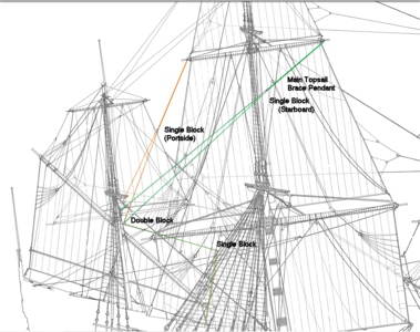
The port and starboard lines then pass forward and down to a single block secured to the aft mainmast shrouds, slightly higher than halfway up the aft main shroud. There is one line starboard and one port and from here the line goes from the single block to deck level and a belaying pin (the second last, aft in this grouping) in the lower railing.
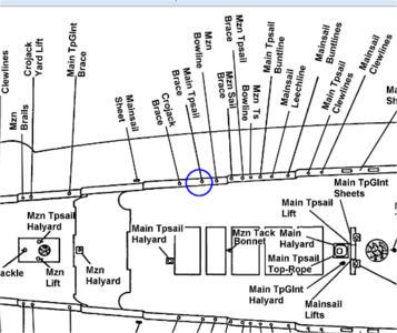
Quite a complex rigging solution but as best I can interpret from the Rigging Plans.
Interestingly, the Billings Rigging Plans show none of this. These plans have a double block above the mizzen topsail mounted to the mizzen mast. This block receives the return lines (L24) from the main topsail pendants and then down through the mizzen mast rigging to the deck.
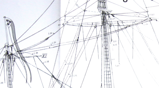
The belaying point is the forwardmost belaying pin of the mizzen railing group (marked L24 as shown below). This is in conflict with the belaying points of the best known Belaying Plan (published again by the museum and others). I guess this would be a simpler way to rig the topsail braces, but not as the museum and Anderson document it.
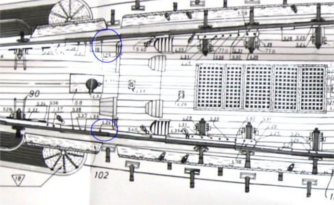
It is probably academic where the brace lines return to the blocks on the mizzen (shrouds or mast), but it may be useful for others and their Vasa builds.
Regards
PeterG
PAUL
Hi Peter,
If you don't mind fielding a question...for the bilateral mizzen stays...it looks like you took the tensioning rope to a hook on the deck (presumably attached to an eyebolt). Is that what you did? Others say the line goes to the 'pin rails' on the deck (which probably didn't exist) and I don't see a belay location for those lines on anyone's belay plans. Thanks for any guidance you can provide.
Paul
PETER RESPONDS
Hi Paul,
... In terms of the 'bilateral mizzen stays', I am not 100% sure I know which lines you are referring to.
So Paul sent a photo with an arrow indicating the line in question and the comment 'See below. Where does this line terminate (and how)? Thank you for taking the time to help me out!'

PETER RESPONDS
Hi Paul,
I thought I had picked the wrong line with what you described as 'bilateral mizzen stays'. The line you are pointing at is the Main Topsail Brace. This line is a complex bit of rigging and is best explained by the run of the rigging in the Vasamuseet plans which I show below.
The Vasamuseet plan for the Main Topsail Brace which I have highlighted, starts with a double secure point on the Mizzen mast just below the mizzen top but just above the Crojack spar. This ensures it will not foul the lower edge of the mizzen topsail when set. From this point, one line goes to the port and one to the starboard single blocks at the end of the Main Topsail pendants connected to this sail's spar ends. After going through these single blocks they return to a double block secured to the forward mizzen mast, again secured just below the Crojack spar and above the mizzen spar parrel. In the plans this is hard to see and I think they may have drawn it a bit low, as it looks to be below the parrels and trucks of the mizzen. This is my interpretation.
An alternative interpretation which is equally plausible, is that the line may return from the brace pendants to a single block mounted on the mizzen forward stay just below the mizzen futtock shrouds. Although this is a plausible way to rig the line, in the museum plans, the lines from both starboard and port brace pendant returns are going to a single block, and this is why I have adopted the former rigging method rather than the latter - Up to you (yet another rigging decision)!!

The port and starboard lines then pass forward and down to a single block secured to the aft mainmast shrouds, slightly higher than halfway up the aft main shroud. There is one line starboard and one port and from here the line goes from the single block to deck level and a belaying pin (the second last, aft in this grouping) in the lower railing.

Quite a complex rigging solution but as best I can interpret from the Rigging Plans.
Interestingly, the Billings Rigging Plans show none of this. These plans have a double block above the mizzen topsail mounted to the mizzen mast. This block receives the return lines (L24) from the main topsail pendants and then down through the mizzen mast rigging to the deck.

The belaying point is the forwardmost belaying pin of the mizzen railing group (marked L24 as shown below). This is in conflict with the belaying points of the best known Belaying Plan (published again by the museum and others). I guess this would be a simpler way to rig the topsail braces, but not as the museum and Anderson document it.

It is probably academic where the brace lines return to the blocks on the mizzen (shrouds or mast), but it may be useful for others and their Vasa builds.
Regards
PeterG


