• LUCZORAMA SHIPWRECK SCAVENGER HUNT GIVEAWAY. 4 Weeks of Fun • 1 Legendary Prize ((OcCre’s Fram Ship)) • Global Crew Welcome!
    **VIEW THREAD HERE**

Which Waterline to build a jig?

Joined
Jan 31, 2021
Messages
661
Points
403

Location
Loveland, CO
I'm at the point where I'm getting ready to build a jig for raising the frames off the keel.

My question is:
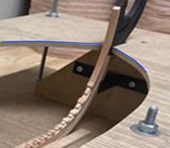
Which waterline do I use to build the profile of the top level? See Photo for what I mean by the top level:
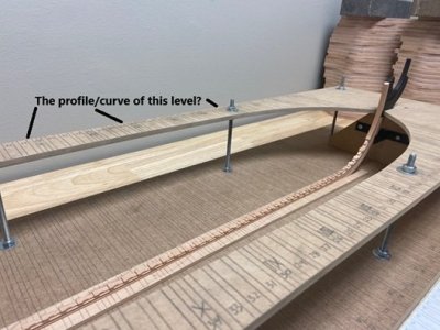
jig.jpg

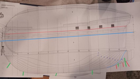
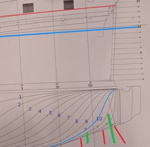
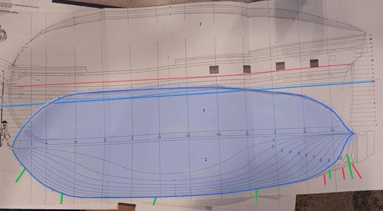
Below are the waterline plans of the Salamandre. My gut tells me to use a single waterline (i.e. the 10ft line marked in green) because it follows the max width/dead perpendicular line most of the way? Any feedback appreciated!
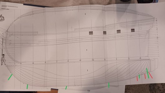
waterlines max.jpg
 
Oh boy, did I ever think about this for weeks. A couple of my resource books suggested the lower deck line - imagine how easy it would then be to lay out gunports, etc. - another of my books suggested the waterline as that was 'straight' - but for my stern section model I ended using the line of maximum breadth. This is the only thing that has worked out well in the last month of my build ROTF.
 
Go with max breadth - on my build its line 10. While does follow the waterline in some places in others it does not.
 
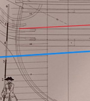
you want to know where this blue line is on the drawings?

jig2.jpg

i think it is the waterline on the drawing when to look at where the jig is at the stem and where the blue line is on the drawing at the stem they look in the same position

waterlines max3.jpg

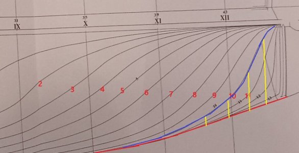
so running a line down the hull it looks like waterline #10


waterlines max.jpg

so i counter the waterlines from 1 to 10 and traced it in blue. The red line is waterline 14 or 15 or the deck line.

the resolution is too low to see what the numbers are on the drawing, that little smudge might be a 5 at waterline i marked as 5


waterlines max 2.jpg
 
Last edited:
Interesting question!
Would it not be best to refer to 'Steel's' data and determine from his reference materials just how far above the water the gunports should be, then do the math from there? I say this because ships have so many water lines with the two most important, for our modeling purposes, being the lightweight water line and the heavy loaded water line. Heavy being for the purpose of locating the level for copper plating, if applicable.
 
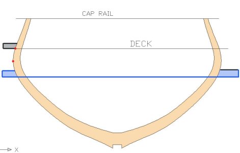
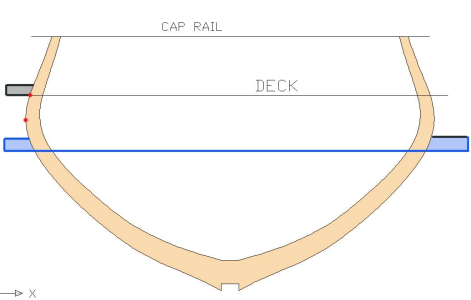
if your asking where to put the jig don't put it at the caprail or deck level. The max breath of the hull is wider and you will never get the frames down to the jig. The red dots
The jig has to be below the widest part of the hull

Capture.JPG
 
Thanks to all for your replies. Your posts have helped me come to a conclusion. Let me explain:

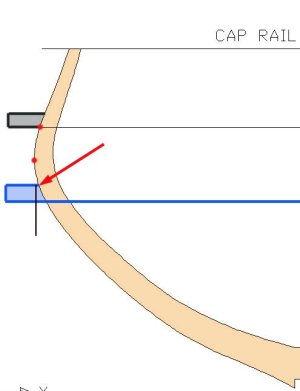
Dave Stevens: You are absolutely right! Anything above the max breadth and frames won't fit, as the hull narrows (your Grey square)! HOWEVER, this got me thinking, any waterline below max breadth (red dot) would "cradle ALL the frames" (your blue squares).
1751762440928.png


Paul and CBL: I agree the max breadth (red line) would allow all frames to fit. HOWEVER, it would leave the aft frame unsupported with the yellow gap.
unsupported stern.jpg

My conclusion is to use the blue 10' waterline (which is max breadth for 90% of the hull. For this 90% the jig walls will be perpendicular. For the last 10%, the frames will be "canted past vertical", so the jig will have to be slightly beveled (like the blue blocks in 1st photo).

My other conclusion is to make the platform as thin as possible and reinforce it longitudinally. This way there is very little to bevel at the aft end. I'm thinking the 0.10" thick plexiglass would work awesome.

Hopefully this discussion makes sense. If I'm off base, let me know because this is the way I intend to proceed. Pictures to follow when I get the jig built.
 
HOWEVER, it would leave the aft frame unsupported with the yellow gap.
I don't believe this is true. But it does mean the upper board is not flat - it curves to follow the maximum breadth line (thus it supports the frames at that vertical position). Or maybe I misunderstand what you're trying to do (or I misunderstand my understanding of the task at hand). Or... ROTF
 
I don't believe this is true. But it does mean the upper board is not flat - it curves to follow the maximum breadth line (thus it supports the frames at that vertical position). Or maybe I misunderstand what you're trying to do (or I misunderstand my understanding of the task at hand). Or... ROTF

the jig using waterline 10 would look like this and follow the hull shape, At the bow and stern the frames are getting narrower and much more of a V bottom Max width would be higher

waterlines jig3.jpg
 
My other conclusion is to make the platform as thin as possible and reinforce it longitudinally. This way there is very little to bevel at the aft end. I'm thinking the 0.10" thick plexiglass would work awesome.

you do not have to bevel the jig edge because the jig is not actually holding the frame in place fore and aft. The jig is a reference point of where the frame is at along waterline 10.
to hold the frame in position you need to notch the jig or use some sort of spacer. it sounds like a lot of work to notch the jig but in the long run it might of been worth it.

go to the school for model shipwrights i talk about jigs

point.jpg
 
I don't believe this is true. But it does mean the upper board is not flat - it curves to follow the maximum breadth line (thus it supports the frames at that vertical position). Or maybe I misunderstand what you're trying to do (or I misunderstand my understanding of the task at hand). Or... ROTF
Spot on....my intention is for the upper board to be flat, and this could not be accomplished following the max breadth line. We're on the same sheet/level/mind-meld.
 
You do not have to bevel the jig edge because the jig is not actually holding the frame in place fore and aft. The jig is a reference point of where the frame is at along waterline 10.
to hold the frame in position you need to notch the jig or use some sort of spacer. it sounds like a lot of work to notch the jig but in the long run it might of been worth it.

Thanks Dave,

Makes perfect sense...the "TOP EDGE" of the jig is the "reference point" for the selected waterline, so it really does not matter how thick the jig board is. Best of all, no beveling required.

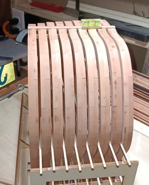
I plan to use spacer timbers that lay from one side of the jig to the other. Similar to the jig in the BHR kit I built below.

PS: I'm headed to your "School for Model Shipwrights" now. Thanks!
frames in jig2.jpg
 
Back
Top