YQ Bluenose by Johan [COMPLETED BUILD]

Oké, confession time.
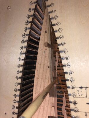
Remember I went AL-FI on the focsle arrangement? I moved the block, holding the bowsprit post down, attaching it to the keel, instead of to the original YQ focsle structure. Checked the drawings, multiple times, counted the frames, again and again. But... the floorbeam, with a cut-out, accommodating the bowsprit post, didn't sit nicely against frame 8. Back to the drawing again. Still coming to the conclusion that the beam with the cut-out should be sitting against frame 8.
That went into the build. And now with the below deck floors nearly complete, I decided to check again and... now I think that bowsprit post block should be moved one frame forward...Sick:eek:

The arrow indicates the hole for the post at frame 7. My current position is that it should be moved one frame forward.
I royally messed up this one.
View attachment 307643
Having given it some more thought, I checked the position of the post with the pre-defined fwd deck part.
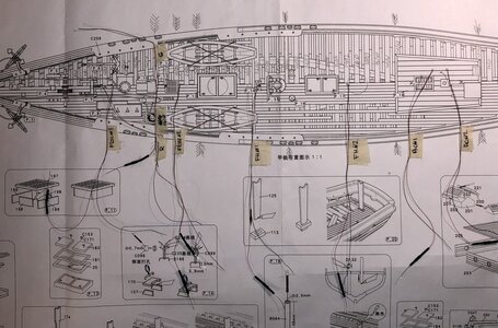
To my utmost surprise, when lining up the two mast holes in the fwd mast base and in the deck, the two holes for the post line up beautifully. Before taking any step further, I’ll sleep on it for a couple of nights and check, double check again. This is getting weird! Something’s not right…
 
Oké, confession time.
Remember I went AL-FI on the focsle arrangement? I moved the block, holding the bowsprit post down, attaching it to the keel, instead of to the original YQ focsle structure. Checked the drawings, multiple times, counted the frames, again and again. But... the floorbeam, with a cut-out, accommodating the bowsprit post, didn't sit nicely against frame 8. Back to the drawing again. Still coming to the conclusion that the beam with the cut-out should be sitting against frame 8.
That went into the build. And now with the below deck floors nearly complete, I decided to check again and... now I think that bowsprit post block should be moved one frame forward...Sick

The arrow indicates the hole for the post at frame 7. My current position is that it should be moved one frame forward.
I royally messed up this one.
View attachment 307643
Having given it some more thought, I checked the position of the post with the pre-defined fwd deck part.
To my utmost surprise, when lining up the two mast holes in the fwd mast base and in the deck, the two holes for the post line up beautifully. Before taking any step further, I’ll sleep on it for a couple of nights and check, double check again. This is getting weird! Something’s not right…
Just did a dry fit of the fwd deck with the bowsprit post and a dummy "mast".
They just line up very nicely.

o_O
View attachment 307668
The block rests between the 2 floor beams which are fitted before the frames 7 and 8.
So, indeed, you mounted it correct!
Regards, Peter
 
The block rests between the 2 floor beams which are fitted before the frames 7 and 8.
So, indeed, you mounted it correct!
Regards, Peter
Thank you so much Peter, what a relief!
The odd thing now remaining is the floorbeam with the recess for the post. That should now be sitting against frame 8, with the recess at the fwd side of the beam. With little to no mounting area against said frame. Needs a little more research.
 
You don't always have to understand the plan. Sometimes we just get lucky - goodness knows, there are enough times when luck is not on our side. Therefore, enjoy this one.
 
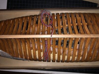
The last couple of days I have been working on nothing related to YQ's building instructions, but instead found myself following some examples, set by fellow builders. As I mentioned, I also paged through the "Saga" and after tossing around some ideas, I lowered the floorsupports in the focsle, simultaneously lowering the bracket for the bowsprit support, added floorsupports for the aft cabin and put in the floors (partial) for those three compartments. Also added is the ceiling on the left side of the hull.
Work on these items is not yet complete, but worth showing.
Also installed is the first ledlight, with a big thanks to @Henk Liebre, in the compartment below the aft cabin. Now it's getting close to start work on the upper decks floorbeams.

Here's first light in the compartment below the aft cabin:

View attachment 307310

A view looking forward, with all three floors partially installed. Some finishing touches are still required.
Sanding, applying finish, touch-ups... In all, I'm pretty happy with how she looks right now.

View attachment 307313
Very impressive Johan Thumbsup
 
Totally and utterly unrelated, but tonight I visited the Sagrada Familia in Barcelona.
An unforgettable event.

I'll limit myself to one picture only:
View attachment 308145
Wow! The symmetry is incredible, surely the designer would have made a good ship builder? Enjoy the visit Johan, I envy your relatively easy access to magnificent structures such as these Thumbsup
 
After spending a week in Barcelona, it's back to the shipyard again.
Since I'm adding, amongst others, some interior parts like lower decks for the focsle, fishholds, the aft cabin and some bulkheads, I wanted to ensure the bulkheads will be installed at the right locations.
First thing I encountered was that, where I was lucky with the location of the Samson post, I ran out of luck with the aft cabin floor; one frame too far forward. Where I went wrong is the following: I counted frames 1 trough whatever on the drawing and then located the required frame in the jig. What I found out was that for the deck beams it's easier and more fool-proof to identify those as for instance beam 41-42, or the beam located between frames 41 and 42, and sitting against frame 42. This given example is the forward beam, bordering the forward side of the aft cabin. Likewise beam 49-50 is the beam, bordering the aft side of the aft cabin.
Where I went wrong was that I identified the first frame where the aft cabin started and yes that's frame 41, but the associated beams is not sitting against frame 41, but instead is between frames 41 and 42. The result now being is that the aft cabin floor is one frame too far forward.
I found out because I dry-fitted the aft deck pre-printed part and found the cut-out not matching with the deck's framework for the aft cabin, if I lined up the main mast base in the keel with the opening in the deck for the main mast.
Time to think on how to solve this issue. Currently, I'm not too inclined to remove the aft cabin floor, since I have very limited access to the bond line of said floor... o_O
While dry-fitting the deck beams of the aft cabin, I also found that where the pitch between frames 41 and 49 is 80mm, the pitch between the two beams with the two longerons temporarily installed measures 82mm and fits very, very tightly between the frames. Effectively, beam 49-50 sits tight against the front side of frame 50, whereas beam 41-42 sits tight against the aft side of frame 41, whereas it is supposed to be sitting against the fronts side of frame 42. At least I've gotten another topic to wreck my grey matter with...

Pitch between frames 42 and 50, 80mm. (The pitch between 41 and 49'is the same.)
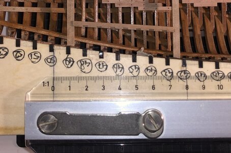
657517ED-3129-4639-877B-B71E61F5BB1D.jpeg

The cut-out in the aft deck sheet: 81mm.
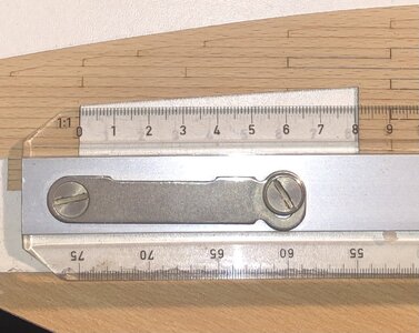
BD867546-FA9B-48F3-8BD2-C2A0BF2D16C7.jpeg

Pitch between the fwd and aft deck beams of the aft cabin equals 82mm, temporary fitted.
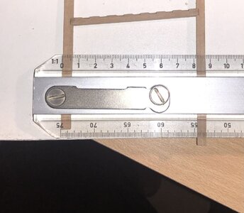
3AE065F7-5D4A-49E7-9D84-82F4EE1B70DB.jpeg

It's hard to see, but the framework is sitting very tight between the frames. What ís clear to see is the fwd beam sitting against the aft side of frame 41, instead of the the fwd side of frame 42.
Once properly trimmed, the fit will improve, but that would be more of a sliding fit, rather than the close to interference fit it is right now.
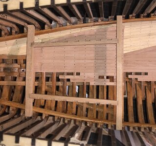
98F052C8-4E2A-44D2-9B1F-72C1414B2989.jpeg
 
Last edited:
The 1st photo is a bit distorted with the depth perspective. The cabine frame is deeper in the jig on the bearing beams and the black frame heads are well above that in the top of the jig.
I was counting for a while and got confused. The front beam looks ahead of frame 42 but is indeed by 41. The perspective shows the front and rear frames obliquely. The last pictures gives a better view.
The cabin frame belongs to frame 41-49. The intermediate beams 42-48 are narrower than the main beams 41 and 49. With some mm differences, something has to be moved. Maybe not place a few tight against the frame?
But if 49 is to far away from the frame, that the space between 49 and 50 is very narrow.
Perhaps a little bit of the head of beam 41, so it slides a bit to the front?
I didn't pay any attention to that because I adjusted my deck beams on the bearing beams and between the clamps. And didn't use the deck sheat. But I take it you're not going to use it either?
Regards, Peter
Ha Peter,
The first picture was only to show the distance between frames 42 and 50 in the jig. That became my starting point. I agree, there's a lot of distortion in the picture; it's very hard to see against which frames the two crossbeams are resting, but the fwd one is supported at the front side by frame 41 and the aft beam is supported on the aft side by frame 50.
Based on the drawings, the crossbeams are all located with the aft face against the fwd face of the frames. Currently crossbeam 49-50 sits properly against frame fifty and crossbeam 41-42 sits firmly with it's fwd face against the aft face of frame 41, instead of against the fwd face of frame 42. I also ran the calcs and yes, the 2mm longer longerons result in beam 41-42 being forced against frame 41.
Based on our earlier conversation (in Dutch) I am strongly leaning towards shortening the two longerons, simultaneously making sure the shorter crossbeams match with the frames 42 trough 48. Before starting this exercise I'll make sure to sleep on it, to see if something unexpected pops up.
Still a little undecided on your clamp-solution, but I'm definitely going for a custom made deck. The pre-shaped decks are used for dry-fitting and checking interfaces.
Thanks, Peter for your advice, it's highly appreciated.
Johan
I'm not sure I fully understand the issue Johan. I did try, although I think Peter has a much better handle on it. I just hope you are able to come to a solution you are happy with. Good luck!
 
I'm not sure I fully understand the issue Johan. I did try, although I think Peter has a much better handle on it. I just hope you are able to come to a solution you are happy with. Good luck!
Hey Nomad,

I'll try and explain...

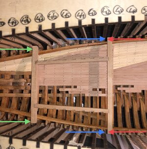
In the picture below you see the basic frame work for the aft cabin; two transverse floorbeams and two longerons, more or less in the longitudinal axis direction.
The two floorbeams should be sitting with their aft side to the fwd side of the adjacent frame, see the green arrows in the picture, where the aft beam sits properly against the frame. The forward beam however doesn't sit against the adjacent aft frame, but instead sits with its fwd side against the aft side of the frame, see red arrows. The blue arrows then show the to-be situation, where the aft side af the beam sits against the fwd face of the adjacent frame, just like his little brother on the aft side of the aft cabin.
I think the root cause is mainly twofold: the frame itself measures 82mm, that does not match the intended pitch of 80mm, as indicated by the jig. Secondly, I know now quite sure, that I have some poorly positioned frames, paying insufficient attention to maintain the pitch between the frames along the entire circumference of the frame.
I hope you now have a somewhat better understanding of the issue.

77FF43E7-CD3B-47A9-95CD-08FBAA10D778.jpeg
 
Last edited:
Back
Top