- Home
- Forums
- Ships of Scale Group Builds and Projects
- Bluenose PoF Group Build
- Bluenose Group Build Logs
You are using an out of date browser. It may not display this or other websites correctly.
You should upgrade or use an alternative browser.
You should upgrade or use an alternative browser.
- Joined
- Sep 3, 2021
- Messages
- 4,228
- Points
- 688

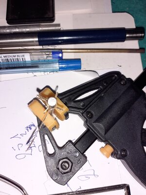
Nice example, Frank.test without welding as View attachment 335717
This folded fitting only needs either a drop of CA-adhesive or a little soldering to nicely close it.
A fully soldered fitting with four eyes will have 4 soldered connections. On top of that, the folded fitting has double the bearing area; it has two flanges, whereas the soldered one only has one flange per eye.
- Joined
- Oct 17, 2020
- Messages
- 1,336
- Points
- 393

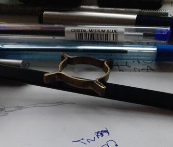
you just have to weld to close and drill theNice example, Frank.
This folded fitting only needs either a drop of CA-adhesive or a little soldering to nicely close it.
A fully soldered fitting with four eyes will have 4 soldered connections. On top of that, the folded fitting has double the bearing area; it has two flanges, whereas the soldered one only has one flange per eye.
Last edited:
- Joined
- Sep 3, 2021
- Messages
- 4,228
- Points
- 688

Correct.you just have to weld to close and drill the View attachment 335732
Quite a few examples of this method being used can be found on this forum. See amongst others @Dean62 and @Peter Voogt. My apologies for those I didn't mention, but also used this method.
The method I used was copied from the suburbanmodeler.
Thank you for mentioning, Johan. The credits rest entirely with Dean @Dean62. Good thing he didn't patent it.Correct.
Quite a few examples of this method being used can be found on this forum. See amongst others @Dean62 and @Peter Voogt. My apologies for those I didn't mention, but also used this method.
The method I used was copied from the suburbanmodeler.
The ‘Suburban’ is also inspiring me!
Regards, Peter
- Joined
- Oct 17, 2020
- Messages
- 1,336
- Points
- 393

I tried to make a contribution to youCorrect.
Quite a few examples of this method being used can be found on this forum. See amongst others @Dean62 and @Peter Voogt. My apologies for those I didn't mention, but also used this method.
The method I used was copied from the suburbanmodeler.
- Joined
- Sep 3, 2021
- Messages
- 4,228
- Points
- 688

And for that you have my thanks!I tried to make a contribution to you
- Joined
- Oct 17, 2020
- Messages
- 1,336
- Points
- 393

Hi Johan, this is not the case, if I can be of any help in my small way just ask.FrankAnd for that you have my thanks!
- Joined
- Jan 9, 2020
- Messages
- 10,377
- Points
- 938

Johan you have made huge progress since my last visit. I have always found it difficult at first to trust myself when I deviated from instructions or building from scratch (is it strong enough, does it look good, is the scale correct, etc.) The more you do it and see that all is well, the more you start trusting your gut feel. If your gut feel tells you that it is not strong enough, make it stronger. Even though it may be well strong enough, you will always doubt it. Personally, I strive to build my models very strong. as it gives me peace of mind.
- Joined
- Sep 3, 2021
- Messages
- 4,228
- Points
- 688

Ha Heinrich, funny you should say that about "huge progress". To me it's like watching grass grow.Johan you have made huge progress since my last visit. I have always found it difficult at first to trust myself when I deviated from instructions or building from scratch (is it strong enough, does it look good, is the scale correct, etc.) The more you do it and see that all is well, the more you start trusting your gut feel. If your gut feel tells you that it is not strong enough, make it stronger. Even though it may be well strong enough, you will always doubt it. Personally, I strive to build my models very strong. as it gives me peace of mind.
But regardless, progress is being made.
Those tiny, soldered eye plates are a lot stronger than I thought; I can lift the model at the bowsprit, using the keel at the rudder as hinge point and those tiny eyes just take the punishment.
After looking at these details for a couple of days now, I am coming to really appreciate the fact that they blend into the background. Mind you, at approx 0,4mm thick, they represent a real life thickness of 28mm, which is rather sturdy...
Still, a small test is in the near future.
- Joined
- Sep 3, 2021
- Messages
- 4,228
- Points
- 688

Currently I am trying g to work out the whole windlass mess on the focsle.
The windlass assembly of the Billing Boats Bluenose (what an alliteration...) is a rather simplified representation of reality and YQ'S version is an improvement, but, as some of my illustrious predecessors already pointed out, still lacking realism.
I most definitely will not try and add all intricate details, but I do want to add some bits and pieces to make the whole windlass drive train appear more realistic.
Since I don't have a large scrap yard, effectively no scrap yard, no lathe or other machining tools, except for some handtools, a Dremel and a sawing machine, I have to do quite a bit of handiwork.
After considering my options I started trying to make some gears and gear supports by hand.
This is my first try. The teeth of the gears are not regular, the gears themselves not circular and the support brackets, we'll, let's forget about them.
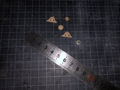
As far as the gears go, I'll pay the local hobby shop a visit later this week, to see if he's gotten anything usable.
The support were subjected to a second try. Instead of making it a single part from some scrap wood, I opted to use wooden strips of varying widths and started bonding parts together.
In the right hand corner of the picture below the second mult-part bracket and in the middle the first try.
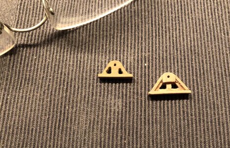
I showed the unfinished parts to the Admiral and she said she couldn't judge until the parts were painted. So I applied some black paint.
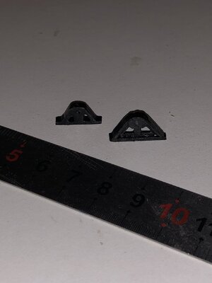
Next step is to a) see if I really want to go forward with this, b) if so, build a second bracket and c) start laying out the windlass drive train; I have a suspicion I'm running of space on the focsle very fast.
The windlass assembly of the Billing Boats Bluenose (what an alliteration...) is a rather simplified representation of reality and YQ'S version is an improvement, but, as some of my illustrious predecessors already pointed out, still lacking realism.
I most definitely will not try and add all intricate details, but I do want to add some bits and pieces to make the whole windlass drive train appear more realistic.
Since I don't have a large scrap yard, effectively no scrap yard, no lathe or other machining tools, except for some handtools, a Dremel and a sawing machine, I have to do quite a bit of handiwork.
After considering my options I started trying to make some gears and gear supports by hand.
This is my first try. The teeth of the gears are not regular, the gears themselves not circular and the support brackets, we'll, let's forget about them.

As far as the gears go, I'll pay the local hobby shop a visit later this week, to see if he's gotten anything usable.
The support were subjected to a second try. Instead of making it a single part from some scrap wood, I opted to use wooden strips of varying widths and started bonding parts together.
In the right hand corner of the picture below the second mult-part bracket and in the middle the first try.

I showed the unfinished parts to the Admiral and she said she couldn't judge until the parts were painted. So I applied some black paint.

Next step is to a) see if I really want to go forward with this, b) if so, build a second bracket and c) start laying out the windlass drive train; I have a suspicion I'm running of space on the focsle very fast.
There is nothing wrong with your handiwork, Johan. The painted parts looks very nice, like little cast-iron parts. Have you set them on the BN to look how the show in this scale?Currently I am trying g to work out the whole windlass mess on the focsle.
The windlass assembly of the Billing Boats Bluenose (what an alliteration...) is a rather simplified representation of reality and YQ'S version is an improvement, but, as some of my illustrious predecessors already pointed out, still lacking realism.
I most definitely will not try and add all intricate details, but I do want to add some bits and pieces to make the whole windlass drive train appear more realistic.
Since I don't have a large scrap yard, effectively no scrap yard, no lathe or other machining tools, except for some handtools, a Dremel and a sawing machine, I have to do quite a bit of handiwork.
After considering my options I started trying to make some gears and gear supports by hand.
This is my first try. The teeth of the gears are not regular, the gears themselves not circular and the support brackets, we'll, let's forget about them.
View attachment 336552
As far as the gears go, I'll pay the local hobby shop a visit later this week, to see if he's gotten anything usable.
The support were subjected to a second try. Instead of making it a single part from some scrap wood, I opted to use wooden strips of varying widths and started bonding parts together.
In the right hand corner of the picture below the second mult-part bracket and in the middle the first try.
View attachment 336553
I showed the unfinished parts to the Admiral and she said she couldn't judge until the parts were painted. So I applied some black paint.
View attachment 336554
Next step is to a) see if I really want to go forward with this, b) if so, build a second bracket and c) start laying out the windlass drive train; I have a suspicion I'm running of space on the focsle very fast.
Regards, Peter.
- Joined
- Sep 4, 2022
- Messages
- 122
- Points
- 113

Johan, do your parts and bits _have to_ be made of wood? The prototypes obviously are a potpourri of iron and/or bronze castings and welded steel bars and angles. Speaking only of my personal preferences, my choice for modeling static metal items is styrene using the myriad of white styrene strips, shapes, and sheets manufactured by Evergreen Scale. The teeny strips have sharp edges, cut cleanly, weld together nicely with no glue ooze-out, have NO grain problems, and come as thin as .010" or about .25mm and range up to 1/4 inch stuff.
- Joined
- Sep 3, 2021
- Messages
- 4,228
- Points
- 688

Thanks Peter!There is nothing wrong with your handiwork, Johan. The painted parts looks very nice, like little cast-iron parts. Have you set them on the BN to look how the show in this scale?
Regards, Peter.
Yeah, I checked the part with a dry fit. I have to start completing all the bits and pieces of the complete train and perform a dry fit to see how my scratch build supports match, scale wise.
Current height of the part is 7,5mm, which is 540mm in real life. The length of the part is more of a concern, but I could potentially fettle 1mm, maybe 2mm from the base. But first a dry fit assembly.
I successfully scored a couple of gears from the hobby shop I mentioned, so no more excuses.
Hello Alf,Johan, do your parts and bits _have to_ be made of wood? The prototypes obviously are a potpourri of iron and/or bronze castings and welded steel bars and angles. Speaking only of my personal preferences, my choice for modeling static metal items is styrene using the myriad of white styrene strips, shapes, and sheets manufactured by Evergreen Scale. The teeny strips have sharp edges, cut cleanly, weld together nicely with no glue ooze-out, have NO grain problems, and come as thin as .010" or about .25mm and range up to 1/4 inch stuff.
No the bits and parts don't need to be made of wood, so your suggestion is a welcome one.
I'll check straight away if there's any availability in the Netherlands of that stuff.
- Joined
- Sep 3, 2021
- Messages
- 4,228
- Points
- 688

Performed a first space allocation exercise. All dry fit, nothing irrevocable. I still need some shafts, bushings and gears, but step by step I'm getting there.
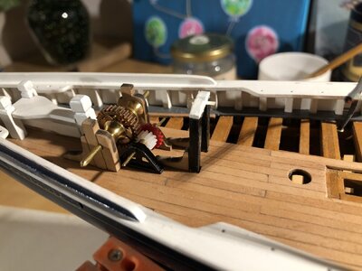
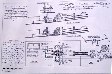
The YQ layout differs somewhat from Jenson's sketches in the Saga; the windlass assembly appears to have been positioned closer to the Samson post, whereas the pitch of the jumbo boom support beams was larger than in YQ'S design, which complicate matters in the space department.
The supports for the in-between drive train are far more slender than my current design. It seems it's back to the drawing board again.

The start is there and the base is set, Johan. Now you have the space in view where this bunch of gears works together to form a nice ‘operating system’.Performed a first space allocation exercise. All dry fit, nothing irrevocable. I still need some shafts, bushings and gears, but step by step I'm getting there.
View attachment 336628
The YQ layout differs somewhat from Jenson's sketches in the Saga; the windlass assembly appears to have been positioned closer to the Samson post, whereas the pitch of the jumbo boom support beams was larger than in YQ'S design, which complicate matters in the space department.
The supports for the in-between drive train are far more slender than my current design. It seems it's back to the drawing board again.
View attachment 336629
Regards, Peter
- Joined
- Sep 4, 2022
- Messages
- 122
- Points
- 113

Your black painted trunnions there look pretty convincing to me; the whole so far seems to be coming together nicely. That's a lot of very small cross-section bits and pieces with a whole bunch of open-spaces between, to be modeling in 1:72. Just keep in mind that each piece is a model in itself. This is the kinds of stuff that small scale railroad modelers (1:87 in North America, something similar in Europe) do all the time. You're off to a good start, Johan.Performed a first space allocation exercise. All dry fit, nothing irrevocable. I still need some shafts, bushings and gears, but step by step I'm getting there.
View attachment 336628
The YQ layout differs somewhat from Jenson's sketches in the Saga; the windlass assembly appears to have been positioned closer to the Samson post, whereas the pitch of the jumbo boom support beams was larger than in YQ'S design, which complicate matters in the space department.
The supports for the in-between drive train are far more slender than my current design. It seems it's back to the drawing board again.
View attachment 336629

- Joined
- Sep 4, 2022
- Messages
- 122
- Points
- 113

Johan, you might look at this 1:87 scale logging donkey engine for an idea of what those railroaders are doing. My understanding is that this model did begin as a kit and the guy detailed it up from there. <<https://markpaulson.wordpress.com/2012/02/28/donkey-engine-in-ho-scale/>>Your black painted trunnions there look pretty convincing to me; the whole so far seems to be coming together nicely. That's a lot of very small cross-section bits and pieces with a whole bunch of open-spaces between, to be modeling in 1:72. Just keep in mind that each piece is a model in itself. This is the kinds of stuff that small scale railroad modelers (1:87 in North America, something similar in Europe) do all the time. You're off to a good start, Johan.
- Joined
- Sep 3, 2021
- Messages
- 4,228
- Points
- 688

Your black painted trunnions there look pretty convincing to me; the whole so far seems to be coming together nicely. That's a lot of very small cross-section bits and pieces with a whole bunch of open-spaces between, to be modeling in 1:72. Just keep in mind that each piece is a model in itself. This is the kinds of stuff that small scale railroad modelers (1:87 in North America, something similar in Europe) do all the time. You're off to a good start, Johan.
Thanks for your encouragements and for the link to Mark Paulson's donkey engine model.Johan, you might look at this 1:87 scale logging donkey engine for an idea of what those railroaders are doing. My understanding is that this model did begin as a kit and the guy detailed it up from there. <<https://markpaulson.wordpress.com/2012/02/28/donkey-engine-in-ho-scale/>>
This model really looks great, especially his weathering efforts paid off, both speaking figuratively ánd literally.
I'm also in contact with @Peter Voogt and I will be paying him a visit next week to discuss amongst others the drive teain. Till then I have some time to reflect on the best way how to proceed and to make some more test parts.
I'm not after a fully accurate representation; my model is not being built for a museum, but for my own enjoyment and I find great fun in adding some details. Especially the preparations, designing and planning, etc, are keeping me on my toes.
- Joined
- Sep 3, 2021
- Messages
- 4,228
- Points
- 688

Since I'll be visiting Peter Voogt this coming week, I stepped away from the whole windlass drive train and found some diversion in the four hatches for the two fishholds.
YQ designed a neat solution for the landings, supporting the hatches. It consists of a base, with rectangular holes, smaller than the hatches. On top of the base a frame is bonded, with holes the size of the hatches. Once bonded, one has the landings and the aperture for the hatches. The hatches themselves are plain rectangular pieces of wood, with a thickness of 2mm, roughly 0,080".
Below the coamings and hatches from YQ for the aft fishhold access:
The top two parts are the hatches, the bonded frame is mid below.
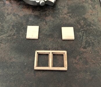
Though pleased with the coamings, I wasn't really satisfied with the hatches.
So I made my own hatches.
The selfmade hatches are inserted into the frame, for treference the YQ access panels are at the bottom of the picture below:
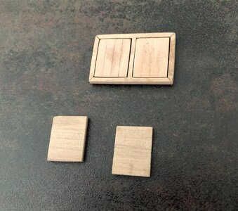
Next steps are to stain the hatches and paint the coaming, than following the same procedure for the fwd hatches.
YQ designed a neat solution for the landings, supporting the hatches. It consists of a base, with rectangular holes, smaller than the hatches. On top of the base a frame is bonded, with holes the size of the hatches. Once bonded, one has the landings and the aperture for the hatches. The hatches themselves are plain rectangular pieces of wood, with a thickness of 2mm, roughly 0,080".
Below the coamings and hatches from YQ for the aft fishhold access:
The top two parts are the hatches, the bonded frame is mid below.

Though pleased with the coamings, I wasn't really satisfied with the hatches.
So I made my own hatches.
The selfmade hatches are inserted into the frame, for treference the YQ access panels are at the bottom of the picture below:

Next steps are to stain the hatches and paint the coaming, than following the same procedure for the fwd hatches.

