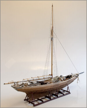
YUANQING BLUENOSE - Peter Voogt [COMPLETED BUILD]

Peter, because of your meticulous documentarian skills you long ago elevated this build log from being only the log of your build, making it instead a highly instructive interactive BN build and superdetailing tutorial.

I wish I had the computer savvy to be able to compile all the meat of this log into a single downloadable and printable document. First weeding out all the extraneous oohhs and aahhs fluff of course (like this very postROTF).
alf in Iowa
 
Last edited:
Peter, because of your meticulous documentarian skills you long ago elevated this build log from being only the log of your build, making it instead a highly instructive interactive BN build and superdetailing tutorial.

I wish I had the computer savvy to be able to compile all the meat of this log into a single downloadable and printable document. First weeding out all the extraneous oohhs and aahhs fluff of course (like this very postROTF).
alf in Iowa
Hi Alf. Thank you very much for this compliments, nice words and ‘oohh&aahh fluff’.;)
So many pages becomes for me also a little problem to find back a post or item.
In certain browsers there are options to export site pages as a PDF. They then become a bit longer but break them up into pages. Perhaps searching for the browser you are using gives some information.
Regards, Peter.
 
The next step is to apply the 'shoe' at the bottom of most of the keel. As show on the drawings in the Saga-book.
It protects against damaging the lower keel bar. The planks are secured with trennels in the keel.

I couldn't find in the book "Bluenose II, Saga of the Great Fishing Schooners" by L.B. Jenson what the length of the keel bars was. The planks for the hull are between 25 and 30 feet. That's between 7.6 and 9.1 meters. My estimate for the shoe is that they were a bit shorter In case of damage, a large shelf did not have to be replaced.

To make the little trennels I have seen different techniques pass by on the forum.
I've been in touch to order a Byrnes Drawplate to try to make them myself.
It’s not delivered yet. So, started with toothpicks.

After first some test pieces with different diameter drills, eventually hatched on the drilling of 0.7mm holes.
Started in the recess for the rudder and then to the point forward.
Because for me this is a new technique, the first 2 pieces are edited in 2 ways.

View attachment 206006
A loose piece of 7.5 x 4.5 mm, containing 5 toothpicks. When dried cut off, sand and glue to the keel.

View attachment 206007
A piece of 2.5 x 4.5mm glued on the keel. After drying 2 holes drilled and glued in 2 toothpicks. After drying cut off and sanded.

View attachment 206008
Fitted on the keel, sanded and polished.
Mwa ……. Not bad for my first attempt.

After this 1st experience decided to mark the holes with a needle on the lat for the next piece of shoe, drill the holes and glue to the keel.
You can see it in the picture. To distribute the pressure and prevent damage on the shoe lat, put an extra bar on it.
Then the next step is to drill deeper so that the glued toothpicks also connected to the keel.

Regards, Peter
Hi Peter. Was curious where you got the wood pieces for the shoe? Did they come from the kit? Thanks!
 
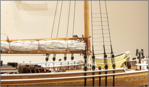
Continued finishing the reeved deadeyes.
In the old photos I thought I saw that the loose ends above the sheer pole were secured with a clove hitch. Given the 2 rope curves around the shroud.
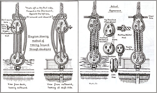
But of course I browsed in The Sage and I came across these drawings by Jenson:
981 Juffer.jpg
-the loose end on the outside around the shroud;
-through the inside back;
-turn over at the top around the loose end and back on the inside;
-return on the outside;
-down through the loop just created;
-pull tight so that the doubled loose ends on the inside of the top deadeye hang down.
So that's a new challenge!
I think you can see that in the old photo on the right in my previous ‘deadeyes reeving’ post.

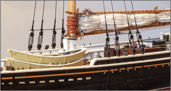
After many hours of knotting, starting over and finally getting the hang of it, this was the result:
982 Juffer.jpg
With the white braces I had not chosen the easiest way to secure the top deadeyes. Because with all 4 tensioned per side, the shere pole also had to run parallel to the railing.

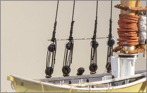
Anyway, just a detail:
983 Juffer.jpg
The black on the sheer pole is reflected a bit by the light with which the photo was taken.
For the detail-lovers: the 2 left and 2 right are mirrored to each other in terms of securing, reeving and tying. Everything "working towards the center".
Was that so on the original BN? No ......... but on my BN it is. This captain is a little crazy.:rolleyes: And it's just fun to think and do everything 'to the left' and 'to the right'. Others probably won't see it. That's just like Uwe's @Uwek nails.:)

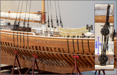
With another (partial) overview picture:
984 Juffer.jpg
With an enlargement in the insert. The space between both deadeyes is only 9mm/.35" Just enough to work with 2 tweezers.
Regards, Mad Peter
 
Last edited:
Continued finishing the reeved deadeyes.
In the old photos I thought I saw that the loose ends above the sheer pole were secured with a clove hitch. Given the 2 rope curves around the shroud.
But of course I browsed in The Sage and I came across these drawings by Jenson:
View attachment 340918
-the loose end on the outside around the shroud;
-through the inside back;
-turn over at the top around the loose end and back on the inside;
-return on the outside;
-down through the loop just created;
-pull tight so that the doubled loose ends on the inside of the top deadeye hang down.
So that's a new challenge!
I think you can see that in the old photo on the right in my previous ‘deadeyes reeving’ post.

After many hours of knotting, starting over and finally getting the hang of it, this was the result:
View attachment 340919
With the white braces I had not chosen the easiest way to secure the top deadeyes. Because with all 4 tensioned per side, the shere pole also had to run parallel to the railing.

Anyway, just a detail:
View attachment 340920
The black on the sheer pole is reflected a bit by the light with which the photo was taken.
For the detail-lovers: the 2 left and 2 right are mirrored to each other in terms of securing, reeving and tying. Everything "working towards the center".
Was that so on the original BN? No ......... but on my BN it is. This captain is a little crazy.:rolleyes: And it's just fun to think and do everything 'to the left' and 'to the right'. Others probably won't see it. That's just like Uwe's @Uwek nails.:)

With another (partial) overview picture:
View attachment 340921
With an enlargement in the insert. The space between both deadeyes is only 9mm/.35" Just enough to work with 2 tweezers.
Regards, Mad Peter
Good evening Mad Peter. Well, I’m “mad” about your BN ;) . Caught up some on your build. Wonderful Peter.
 
Started with the ratlines:
View attachment 341049
Also used the thin Serafil here. They are only fitted between the front shrouds.
I immediately stretched the 1 after the top one so that it also hangs a bit. That's the advantage of looking at the photo again.
Regards, Peter
Ratlines: such a boring job, but once finished, utterly rewarding.
I think your selection of the diameters of the shrouds and the ratlines are matching the scale.
 
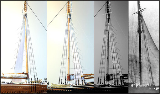
All ratlines are set to starboard. And then I forget to take a picture. Before knotting I used the paper templates I made to measure the shrouds. There lines drawn every 5.5 mm/.216". Because Chapelle had mentioned that they were every 16 inches = 40,6cm. That would be 5.6mm / .220 in 1:72. Just rounded up in mm, more easy to calculate and draw.
Here's a picture of the current state:
986 Weef.jpg
In order from left to right:
-starboard with 46 ratlines;
-port side with the paper template. Knotted a line every 4 to keep the distance between the wall shrouds correct. So that you don't pull them together while tying.

Isn't 46 ratlines a bit to much?
-the 2nd photo converted to grayscale;
-cropped a photo of the original BN and placed it next to it. Counting is allowed, maybe I have one in the plus or the minus …… ;)
Only 1 row of ratlines can be seen on that last photo. That has been mentioned before: a lot of ratlines were removed before a race. Much was done to gain speed.:)
Regards, Peter
 
Last edited:
All ratlines are set to starboard. And then I forget to take a picture. Before knotting I used the paper templates I made to measure the shrouds. There lines drawn every 5.5 mm/.216". Because Chapelle had mentioned that they were every 16 inches. That would be 5.6mm / .220 in 1:72. Just rounded up in mm, more easy to calculate and draw.
Here's a picture of the current state:
View attachment 341748
In order from left to right:
-starboard with 46 ratlines;
-port side with the paper template. Knotted a line every 4 to keep the distance between the wall shrouds correct. So that you don't pull them together while tying.

Isn't 46 ratlines a bit to much?
-the 2nd photo converted to grayscale;
-cropped a photo of the original BN and placed it next to it. Counting is allowed, maybe I have one in the plus or the minus …… ;)
Only 1 row of ratlines can be seen on that last photo. That has been mentioned before: a lot of ratlines were removed before a race. Much was done to gain speed.:)
Regards, Peter
Good afternoon Peter. You did your calculations and that says 46 is correct. I guess the fact some were removed when racing makes it a bit variable and modelers choice. Aesthetically I think less would not look so good. Cheers Grant
 
Good afternoon Peter. You did your calculations and that says 46 is correct. I guess the fact some were removed when racing makes it a bit variable and modelers choice. Aesthetically I think less would not look so good. Cheers Grant
Thanks, Grant. I made the choice to build here as a fishing schooner. As a racer the windlass engine, the dories, the anchor chain and parts of the fish holds and interior where also removed. That would have saved me a lot of work, but it does result in a leaner model.
And I agree with you, aesthetically this looks better.
Regards, Peter
 
Good afternoon Peter. You did your calculations and that says 46 is correct. I guess the fact some were removed when racing makes it a bit variable and modelers choice. Aesthetically I think less would not look so good. Cheers Grant
Hey Grant, I wholeheartedly agree with you; I think 46 ratlines are correct, give or take a few. Especially Peter's statement that ratlines were removed before racing and later reinstalled, gives way to assuming any number between 40 and 50 is fair game. I would say the pitch between the ratlines would vary between 360mm and 450mm. Not your typical steps size for standard stairs, but I don't think these kind of things were heavily standardized these days.
And on top of it all, the 46 ratlines do look very good; too few or too many and you loose the sense of scale.
 
After a while, the port side was also ready:
987 Weef.jpg

Then fitted both topmast shrouds:
988 TopShroud.jpg
These run from the top through the clips on the outside of the long front spreader.
Still the disturbing temporary forestay in the picture, but there is no other way.
989 TopShroud.jpg
For the observant viewer, 2 points:
1: I moved the top sail to the port side. The underside lies over the small back spreader to starboard. If it is sailed on that port side, it will also be furled on that side. Jenson's drawings were a bit confusing. To visualize things properly, he has drawn some items on a different side. And explained elsewhere.
2: on the main cabin I replaced the small standing chimney with a angled one with exit to port side. The standing one came out right under the boom with tackle. First of all, it gets a little warm there. Secondly, I no longer had room to remove the roof to view the interior of the cabin.;)

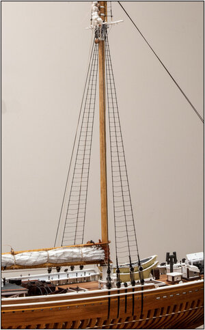
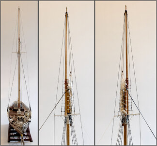
To avoid a very long photo, here's the front view as well as 2 photos of the top mast:
990 TopShroud.jpg
For orientation: the black temporary stay points forward and is attached to the bracket at the front.
Between the iron futtock shrouds also some ratlines. The crew must climb safe to the end.:)

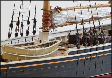
With another picture of how the deadeyes look now:
991 Deadeyes.jpg
The shrouds and lanyard are 0.45 mm / .0177".
The topmast shroud and lanyard are 0.35 mm / .0137". This is not attached to the sheer pole, but more or less straight up to the long front spreader bar.
Regards, Peter
 
Last edited:
Back
Top