- Home
- Forums
- Ships of Scale Group Builds and Projects
- Bluenose PoF Group Build
- Bluenose Group Build Logs
You are using an out of date browser. It may not display this or other websites correctly.
You should upgrade or use an alternative browser.
You should upgrade or use an alternative browser.
YUANQING BLUENOSE - Peter Voogt [COMPLETED BUILD]
- Thread starter Peter Voogt
- Start date
- Watchers 67
Thanks, Paul. I try to maintain my own 'standerd'.What's not to love Peter! Your work at this scale is unmatched.
Regards, Peter
Thanks, Johan. Thanks to the blocks of Zolly and the ropes of Ben.Absolutely gorgeous.
The thread and blocks supplied with the model are rather not to scale. Your selection of thread diameters and block dimensions add to the scale and do justice to the actual size of the model.
Regards, Peter
Last edited:
Thanks, Stephan. And also the top of the BN is rigged.Top, just top
Regards, Peter
Thank you very ver much, Heinrich. Sometimes I surprise myself a little too .....One can rightly ask - is there no boundary to this man's talent? My cap is doffed to you sir accompanied by three, deep bows.
Regards, Peter
The throat halliard fitted between the gaff and the top of the lower mast.
This is done in a special way on the schooners. Both ends of the line are finally secured to a belaying pin.
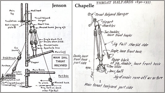
Both Jenson and Chapelle have made clear sketches:
An additional halliard has been installed on the starboard side.
For that extra drop a 3.5mm/.14" double disc block with 2 eyes:

Attached the 0.45mm/.018" line to the larger eye and the 0.35mm/.014" line to the smaller eye.
Then shaved the entire throat halliard:
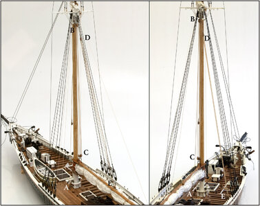
A: On the port side, the hauling leg of the thick line runs through a block on the deck to a belay pin on the fife rail at the mast foot.
B: The thick line goes from the front through the left double sheave block at the rear underside of the lower mast.
C: From B it goes through the left single disc block on the 'spectacle iron' on the claw of the gaff. Then again to the left double block at B, back to the right double block at C, up to the right double block at B, through the right block at C again and back to B.
D: After the last pull through by B, the end of the thick line is attached to the double block of the extra halliard.
E: The thin line goes through both double disk blocks. The bottom block is hooked to an eyebolt on the table between the back two shrouds. The pulling part of the line is secured after the last pull through the block D to a belaying pin just before the hook block.
Because the gaff has been taken down, the block D is now almost at the top at B. Setting the mainsail with the gaff is therefore done by tightening both hauling parts. As Jenson mentioned, the thick line on the port side using the winch.
Some detail pictures. The capital letters in de text are corresponding with them in de 2 pictures above.
The top of the lower mast with the two double sheave blocks (B) on the unster iron:
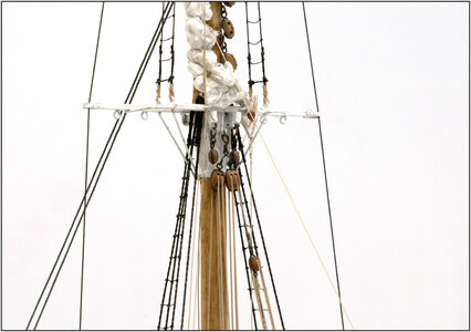
Diagonally right there under the top block of the extra halliard (D).
Above the claw the spectacle-iron with the two blocks (C):
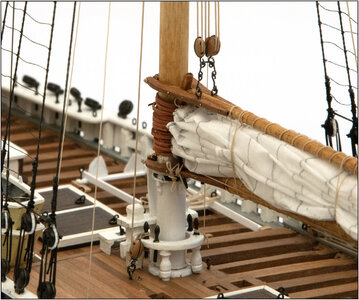
To the left of the fife rail the block (A) on the deck and the running part secured to the belaying pin.
The attachment of the extra halliard to the table:
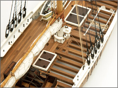
With some more lines in the picture that I have put and shown earlier.
Regards, Peter
This is done in a special way on the schooners. Both ends of the line are finally secured to a belaying pin.
Both Jenson and Chapelle have made clear sketches:

An additional halliard has been installed on the starboard side.
For that extra drop a 3.5mm/.14" double disc block with 2 eyes:

Attached the 0.45mm/.018" line to the larger eye and the 0.35mm/.014" line to the smaller eye.
Then shaved the entire throat halliard:

A: On the port side, the hauling leg of the thick line runs through a block on the deck to a belay pin on the fife rail at the mast foot.
B: The thick line goes from the front through the left double sheave block at the rear underside of the lower mast.
C: From B it goes through the left single disc block on the 'spectacle iron' on the claw of the gaff. Then again to the left double block at B, back to the right double block at C, up to the right double block at B, through the right block at C again and back to B.
D: After the last pull through by B, the end of the thick line is attached to the double block of the extra halliard.
E: The thin line goes through both double disk blocks. The bottom block is hooked to an eyebolt on the table between the back two shrouds. The pulling part of the line is secured after the last pull through the block D to a belaying pin just before the hook block.
Because the gaff has been taken down, the block D is now almost at the top at B. Setting the mainsail with the gaff is therefore done by tightening both hauling parts. As Jenson mentioned, the thick line on the port side using the winch.
Some detail pictures. The capital letters in de text are corresponding with them in de 2 pictures above.
The top of the lower mast with the two double sheave blocks (B) on the unster iron:

Diagonally right there under the top block of the extra halliard (D).
Above the claw the spectacle-iron with the two blocks (C):

To the left of the fife rail the block (A) on the deck and the running part secured to the belaying pin.
The attachment of the extra halliard to the table:

With some more lines in the picture that I have put and shown earlier.
Regards, Peter
Last edited:
- Joined
- Sep 4, 2022
- Messages
- 122
- Points
- 113

Collecting all these rigging pics, you are "out-handbooking" The Gaff Rig Handbook".The throat halliard fitted between the gaff and the top of the lower mast.
This is done in a special way on the schooners. Both ends of the line are finally secured to a belaying pin.
Both Jenson and Chapelle have made clear sketches:
View attachment 342323
An additional halliard has been installed on the starboard side.
For that extra drop a 3.5mm/.14" double disc block with 2 eyes:
View attachment 342318
Attached the 0.45mm/.018" line to the larger eye and the 0.35mm/.014" line to the smaller eye.
Then shaved the entire throat halliard:
View attachment 342319
A: On the port side, the hauling leg of the thick line runs through a block on the deck to a belay pin on the fife rail at the mast foot.
B: The thick line goes from the front through the left double sheave block at the rear underside of the lower mast.
C: From B it goes through the left single disc block on the 'spectacle iron' on the claw of the gaff. Then again to the left double block at B, back to the right double block at C, up to the right double block at B, through the right block at C again and back to B.
D: After the last pull through by B, the end of the thick line is attached to the double block of the extra halliard.
E: The thin line goes through both double disk blocks. The bottom block is hooked to an eyebolt on the table between the back two shrouds. The pulling part of the line is secured after the last pull through the block D to a belaying pin just before the hook block.
Because the gaff has been taken down, the block D is now almost at the top at B. Setting the mainsail with the gaff is therefore done by tightening both hauling parts. As Jenson mentioned, the thick line on the port side using the winch.
The top of the lower mast with the two double sheave blocks (B) on the unster iron:
View attachment 342320
Diagonally right there under the top block of the extra halliard (D).
Above the claw the spectacle-iron with the two blocks (C):
View attachment 342321
To the left of the fife rail the block (A) on the deck and the running part secured to the belaying pin.
The attachment of the extra halliard to the table:
View attachment 342322
With some more lines in the picture that I have put and shown earlier.
Regards, Peter
Thanks, Stephan. First thinking and planning, now building and satisfied!.Like I said on the Dutch forum, perfect in scale.
When you zoom in you see almost no model.
Regards, Peter
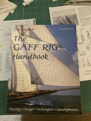
Thanks Alf. I am going to search ……. Looks a very fine book, in addition to what I already have. Always interesting.Collecting all these rigging pics, you are "out-handbooking" The Gaff Rig Handbook".View attachment 342324
Regard, Peter
- Joined
- Sep 3, 2021
- Messages
- 4,236
- Points
- 688

Again, these pictures clearly show it pays handsomely when one properly scales down, thus creating a model, reflecting the true size and beauty of her full size namesake.The throat halliard fitted between the gaff and the top of the lower mast.
This is done in a special way on the schooners. Both ends of the line are finally secured to a belaying pin.
Both Jenson and Chapelle have made clear sketches:
View attachment 342323
An additional halliard has been installed on the starboard side.
For that extra drop a 3.5mm/.14" double disc block with 2 eyes:
View attachment 342318
Attached the 0.45mm/.018" line to the larger eye and the 0.35mm/.014" line to the smaller eye.
Then shaved the entire throat halliard:
View attachment 342319
A: On the port side, the hauling leg of the thick line runs through a block on the deck to a belay pin on the fife rail at the mast foot.
B: The thick line goes from the front through the left double sheave block at the rear underside of the lower mast.
C: From B it goes through the left single disc block on the 'spectacle iron' on the claw of the gaff. Then again to the left double block at B, back to the right double block at C, up to the right double block at B, through the right block at C again and back to B.
D: After the last pull through by B, the end of the thick line is attached to the double block of the extra halliard.
E: The thin line goes through both double disk blocks. The bottom block is hooked to an eyebolt on the table between the back two shrouds. The pulling part of the line is secured after the last pull through the block D to a belaying pin just before the hook block.
Because the gaff has been taken down, the block D is now almost at the top at B. Setting the mainsail with the gaff is therefore done by tightening both hauling parts. As Jenson mentioned, the thick line on the port side using the winch.
The top of the lower mast with the two double sheave blocks (B) on the unster iron:
View attachment 342320
Diagonally right there under the top block of the extra halliard (D).
Above the claw the spectacle-iron with the two blocks (C):
View attachment 342321
To the left of the fife rail the block (A) on the deck and the running part secured to the belaying pin.
The attachment of the extra halliard to the table:
View attachment 342322
With some more lines in the picture that I have put and shown earlier.
Regards, Peter
Last edited:
- Joined
- Sep 4, 2022
- Messages
- 122
- Points
- 113

Studying this, it's apparent that those ship builders and operators took extraordinary measures to mitigate the weight and stresses of that main gaff. I wouldn't begin to estimate, but try to imagine even just the static weight of all that sail cloth both dry and when wet, the weight of the timber, and all the cordage hanging about. Now add in the dynamic stresses involved with air pressure (wind) pushing against the whole, and finally get all that reduced down to a level which could be reasonably manipulated by men applying tension to only two ropes. Gimminy!The throat halliard fitted between the gaff and the top of the lower mast.
This is done in a special way on the schooners. Both ends of the line are finally secured to a belaying pin.
Both Jenson and Chapelle have made clear sketches:
View attachment 342323
An additional halliard has been installed on the starboard side.
For that extra drop a 3.5mm/.14" double disc block with 2 eyes:
View attachment 342318
Attached the 0.45mm/.018" line to the larger eye and the 0.35mm/.014" line to the smaller eye.
Then shaved the entire throat halliard:
View attachment 342319
A: On the port side, the hauling leg of the thick line runs through a block on the deck to a belay pin on the fife rail at the mast foot.
B: The thick line goes from the front through the left double sheave block at the rear underside of the lower mast.
C: From B it goes through the left single disc block on the 'spectacle iron' on the claw of the gaff. Then again to the left double block at B, back to the right double block at C, up to the right double block at B, through the right block at C again and back to B.
D: After the last pull through by B, the end of the thick line is attached to the double block of the extra halliard.
E: The thin line goes through both double disk blocks. The bottom block is hooked to an eyebolt on the table between the back two shrouds. The pulling part of the line is secured after the last pull through the block D to a belaying pin just before the hook block.
Because the gaff has been taken down, the block D is now almost at the top at B. Setting the mainsail with the gaff is therefore done by tightening both hauling parts. As Jenson mentioned, the thick line on the port side using the winch.
Some detail pictures. The capital letters in de text are corresponding with them in de 2 pictures above.
The top of the lower mast with the two double sheave blocks (B) on the unster iron:
View attachment 342320
Diagonally right there under the top block of the extra halliard (D).
Above the claw the spectacle-iron with the two blocks (C):
View attachment 342321
To the left of the fife rail the block (A) on the deck and the running part secured to the belaying pin.
The attachment of the extra halliard to the table:
View attachment 342322
With some more lines in the picture that I have put and shown earlier.
Regards, Peter
Thanks (againAgain, these pictures clearly shows it pays handsomely when one properly scales down, thus creating a model, reflecting the true size and beauty of her full size namesake.
Regards, Peter
Last edited:
Hi Alf. Don't forget for lifting the gaff have to come also the Peak Halliard, also with 2 running ends.Studying this, it's apparent that those ship builders and operators took extraordinary measures to mitigate the weight and stresses of that main gaff. I wouldn't begin to estimate, but try to imagine even just the static weight of all that sail cloth both dry and when wet, the weight of the timber, and all the cordage hanging about. Now add in the dynamic stresses involved with air pressure (wind) pushing against the whole, and finally get all that reduced down to a level which could be reasonably manipulated by men applying tension to only two ropes. Gimminy!
And on the boom the Topping and Quarter lifts. As so named bij Lankford. Jenson is mentions 3 lifts: the Forwards, Middle and End lifts.
But all-encompassing: still impressive how they kept that big sail under control.
Regards, Peter
- Joined
- Sep 4, 2022
- Messages
- 122
- Points
- 113

Hmph! I did forget those. Even more impressive then, the chore of lifting and manipulating that mass and bulk, coordinating four teams of men.Hi Alf. Don't forget for lifting the gaff have to come also the Peak Halliard, also with 2 running ends.
And on the boom the Topping and Quarter lifts. As so named bij Lankford. Jenson is mentions 3 lifts: the Forwards, Middle and End lifts.
But all-encompassing: still impressive how they kept that big sail under control.
Regards, Peter
- Joined
- Sep 3, 2021
- Messages
- 4,236
- Points
- 688

And to add to misery, the waves would increase the loads even more and would also make handling those sails even more of a challenge, especially in the dark ánd under horrendous weather conditions...Studying this, it's apparent that those ship builders and operators took extraordinary measures to mitigate the weight and stresses of that main gaff. I wouldn't begin to estimate, but try to imagine even just the static weight of all that sail cloth both dry and when wet, the weight of the timber, and all the cordage hanging about. Now add in the dynamic stresses involved with air pressure (wind) pushing against the whole, and finally get all that reduced down to a level which could be reasonably manipulated by men applying tension to only two ropes. Gimminy!

My next step would be to fit the main boom with the Topping Lift and the Quarter Lift more or less halfway. And while I'm working on that rear, also the Flying Backstays.
Because I want to put the diameters of the standing rigging in relation to each other, I found the sizes on the MS/Lankford drawings for these lifts to be 'remarkably sturdy': .027"/0.7mm. That is for my scale 1:72 .024"/0.6mm. Decided to first put all the sizes of the stays in a list.
In Jenson's Saga I had found his overview of all the ropes on page 20. Both placed side by side with the values in mm for the scale 1:72:
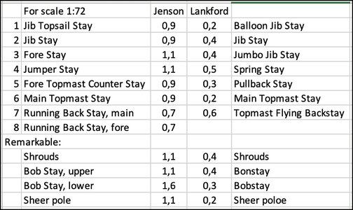
With some notable differences in name and:
-Jenson's diameters are much larger than Lankford's.
-many other lines were much more in proportion with both.
-Lankford does not mention a foremast straight/back stay.
With regard to the foremast backstay I want to know more.
Jenson has his drawings on the pages there. 32 and 120 even made 2 small drawings for clarification. In the Nova Scotia Archive I went looking for a photo with all the stages visible. Most photos are with the wind in the direction of the photographer, so that all the sails were in his direction and thus obscured the view of the stays. Found the following though:
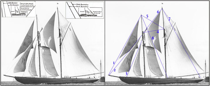
Left without clarification, right with the stays with the numbering from my excel file. And the insert with the 2 extra small drawings from Jenson.
There you can 'clearly see' the foremast backstay. And attached just in front of the shrouds of the main boom.
But to be fair, there are also old photos that don't show this one.
Lankford does show in his drawing that the rear Flying Backstay can be moved to just behind the main mast.
Let's see if I can dig up some additional stuff. Eisnor mentions even less in his drawings.
Because I was still busy putting a lot of values from the Jenson overview in Excel and converting them to 1:64 and 1:72, I have now everything from the table on page 20 put into excel.I will place this file in the Main Support Page.
PS: Meanwhile the list posted:
Regards, Peter
Because I want to put the diameters of the standing rigging in relation to each other, I found the sizes on the MS/Lankford drawings for these lifts to be 'remarkably sturdy': .027"/0.7mm. That is for my scale 1:72 .024"/0.6mm. Decided to first put all the sizes of the stays in a list.
In Jenson's Saga I had found his overview of all the ropes on page 20. Both placed side by side with the values in mm for the scale 1:72:

With some notable differences in name and:
-Jenson's diameters are much larger than Lankford's.
-many other lines were much more in proportion with both.
-Lankford does not mention a foremast straight/back stay.
With regard to the foremast backstay I want to know more.
Jenson has his drawings on the pages there. 32 and 120 even made 2 small drawings for clarification. In the Nova Scotia Archive I went looking for a photo with all the stages visible. Most photos are with the wind in the direction of the photographer, so that all the sails were in his direction and thus obscured the view of the stays. Found the following though:

Left without clarification, right with the stays with the numbering from my excel file. And the insert with the 2 extra small drawings from Jenson.
There you can 'clearly see' the foremast backstay. And attached just in front of the shrouds of the main boom.
But to be fair, there are also old photos that don't show this one.
Lankford does show in his drawing that the rear Flying Backstay can be moved to just behind the main mast.
Let's see if I can dig up some additional stuff. Eisnor mentions even less in his drawings.
Because I was still busy putting a lot of values from the Jenson overview in Excel and converting them to 1:64 and 1:72, I have now everything from the table on page 20 put into excel.
PS: Meanwhile the list posted:
Rigging and Block Measurements by Jenson, Lankford and Chapelle
As mentioned in my build log of the BN, I was looking for the dimensions for the stays and lifts. Not necessarily for the 'adsolute values' but for the dimensions in relation to each other. L.B. Jenson has made an overview in The Saga on page 20 "Standing and Running Rigging Schedule & Block...
shipsofscale.com
Last edited:


