YUANQING BLUENOSE - Peter Voogt [COMPLETED BUILD]

Yes in theory you can. But just think of all the work that has preceded this particular point. For this stage to pan out to equal distances, would assume that ALL work to now - over a space of 57 frames - had to be executed perfectly. Even on the best automated automobile assembly lines where there is still a certain amount of "fine-tuning" required. Show me a perfect builder and I will show you a boring build!
 
Show me a perfect builder and I will show you a boring build!
...a false statement, IMHO. A perfect builder makes a perfect build log, doesn't necessarily have to be bored. Why would we strive for perfection, then? Let's use old school tools, methods\technology to make things interesting :p
In my old country (USSR), we have used the mallet\hummer for all kinds of repairs. Simply because we didn't have a proper tool for a given job. Trust me it wasn't bored at all, it was fun...if you can say that. :cool:
 
@Jimsky You contradict yourself. You just said yourself what fun the mallet/hammer was. THAT was certainly not boring, because you were building/creating.constructing. If you have a perfect kit, you would not be a model BUILDER, you would simply ASSEMBLE the pieces. Come on ...
 
With a high positive contribution: One of the parts #28 was perfect aligned. Just only removed some char (like a big coffee brand: "What else") and it slides direct to its place. Easy the assemble ;).
Hopefully my build-log is not boring and luckily I am not a perfect builder. Take a good look at the bow and stern. ;)
Regards, Peter
 
@Jimsky You contradict yourself. You just said yourself what fun the mallet/hammer was. THAT was certainly not boring, because you were building/creating.constructing. If you have a perfect kit, you would not be a model BUILDER, you would simply ASSEMBLE the pieces. Come on ...
I have no contradictions :cool: It was said in a humorous way. I wish no one even try repairing all kinds of problems with mallet\hummer. Any kit assumes an assembly whether it is perfect or not so. Personally, I am Ok with challenges, but some people may not.
 
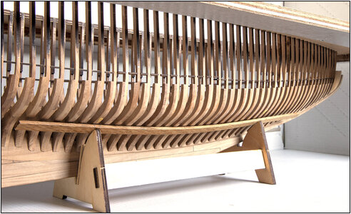
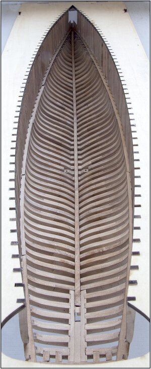
All in all, the spacers went in smoothly. Everything Dry-Fit, because a final placement will follow on the deck later.
Then the inside can now be sanded so that the frames comes in a smooth line. So that the inner beams (and partial planking) can be installed with a smooth connection. The spacers give the frames more strength halfway and especially at the thin single parts.
The hull feels comfortably strong now.
From 3 points of view, the last one shows her beautiful curves. The sanding of the outside will (probably) come later. But yeah.....you never know......
144 Spacers.jpg
145 Spacers.jpg
146 Spacers.jpg
There is no pain, you are receding
A distant ship smoke on the horizon
You are only coming through in waves
Your lips move but I can't hear what you're saying
When I was a child I had a fever
My hands felt just like two balloons
Now I've got that feeling once again
I can't explain, you would not understand
This is not how I am
I have become comfortably numb​
(Yes, a long time ago I played that as a soloist on my E-flat tuba)
Regards, Peter
 
The waterway boards will always require adjustments. I spent a lot of time with a file and test fitting them to get it correct. But that was making the width in the slot correct, and also the width between slots equal.
My approach was to ensure that the frames aligned with the waterway boards, and if I had to, I pulled the frames into the slots at assembly to correct any distance between frames that wasn’t correct.
If you adjust the slot to the frame, then you are not accomplishing anything other than making the waterway board fit. So I used the waterway board to adjust any incorrect distance between frames. ;)
Hi Dean,
That was exactly my approach. The distance between some frames was halfway not exactly the same everywhere. But correct in the jig and on the keel. Some were, because of all the different connections, a little bit skewed. That is why I took the recesses in the spacers as the reference. With the mentioned 10.3mm jumps everywhere. And then the frames slide in or, by some, pulled into the spacers.
Regards, Peter.
 
Last edited:
One of the parts #28 was perfect aligned and it slides direct to its place.
With this line about part 28, it meant that the frames on that part were also nicely straight between the jig and the keel. With the correct space between all of them.
It is sometimes difficult to properly translate my Dutch thoughts into English. ;)
And the auto-correction of Mr. Apple sometimes ‘throws a spanner in the works’. :mad: If that is correct?
Regards, Peter
 
Last edited:
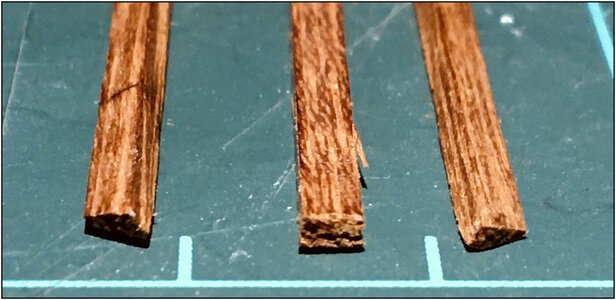
Made a start with the sisters keelson. Found some 2.35x1.80 mm in my wood collection.
The first beams are sanded at an angle. Because they lie next to the keelson in the oblique connection with the frames:
147 Sister.jpg
The lengths will fall on average over 7 frames:
148 Sister.jpg
That's 72.1mm / 2,83”. 1:1 it would be around 5.20 mtr / 204” / 17 ft.
They will also fastened with the iron cup-burrred nails (+/- 120 ;)).
Now sand all 14 beams into shape i.c.w. sanding the inside.
Regards, Peter
 
Last edited:
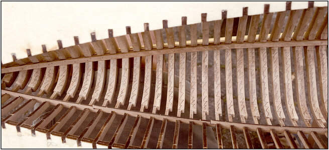
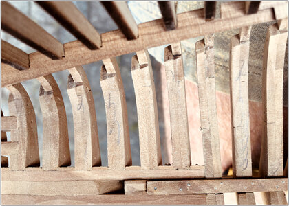
Started sanding the inside. First the frames accentuated with a pencil:
149 Sand.jpg
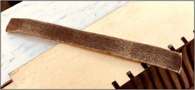
On a strip of thin plywood glued a piece of sandpaper.
150 Sand.jpg
That is pliable and the ends slightly bent. So you can follow the inner curve without the ends always bumping against the frames.
Now a matter of sanding back and forth across the width of several rafters until all the pencil marks are gone.
Here I am almost there:
151 Sand.jpg
Flatten out a few more parts.

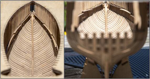
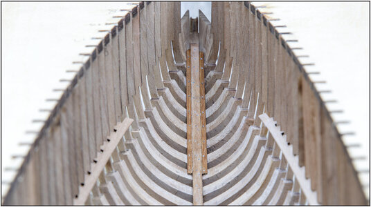
A few hours later I was fine. In the garden, when partial “The Sun was Eclipsed by the Moon” :) some pictures were taken. That is still hard light, but it works well for the contrast between the frames.
Also play with the sharpness/depth a bit:
152 Sand.jpg
Thanks to the spacers, the frames are locked in so they do not bend back and forth during the sanding.

The inside is now ready to install the necessary beams.
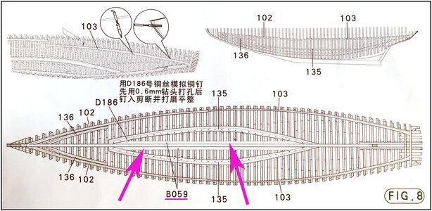
As mentioned, the sisters keelson are not listed in this way in the YQ manual.
There, 2 strips, which are also used as hull planks, are placed in the middle against the keelson:
153 Sister.jpg
But according to the previously mentioned Saga, the sisters keelson runs along the entire length of the keelson.
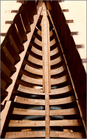
Installed the first 2 pieces in the bow. Gluing, fixing, drilling, nailing:
154 Sister.jpg
For this picture, I took away the 2 spacers in the front.
Perhaps they have used the same wood by the original BN. Depending on the incidence of light, they now accentuate the longitudinal direction slightly more. That is a nice counterpart for all the transverse frames.

Up to the stern.
Regards, Peter
 
Last edited:
Started sanding the inside. First the frames accentuated with a pencil:
View attachment 238061
On a strip of thin plywood glued a piece of sandpaper.
View attachment 238062
That is pliable and the ends slightly bent. So you can follow the inner curve without the ends always bumping against the frames.
Now a matter of sanding back and forth across the width of several rafters until all the pencil marks are gone.
Here I am almost there:
View attachment 238063
Flatten out a few more parts.

A few hours later I was fine. In the garden, when partial “The Sun was Eclipsed by the Moon” :) some pictures were taken. That is still hard light, but it works well for the contrast between the frames.
Also play with the sharpness/depth a bit:
View attachment 238064
Thanks to the spacers, the frames are locked in so they do not bend back and forth during the sanding.

The inside is now ready to install the necessary beams.
As mentioned, the sisters keelson are not listed in this way in the YQ manual.
There, 2 strips, which are also used as hull planks, are placed in the middle against the keelson:
View attachment 238065
But according to the previously mentioned Saga, the sisters keelson runs along the entire length of the keelson.
Installed the first 2 pieces in the bow. Gluing, fixing, drilling, nailing:
View attachment 238066
For this picture, I took away the 2 spacers in the front.
Perhaps they have used the same wood by the original BN. Depending on the incidence of light, they now accentuate the longitudinal direction slightly more. That is a nice counterpart for all the transverse frames.

Up to the stern.
Regards, Peter
I am tempted to build another Bluenose from plans, and add the complete ship below the deck. I would then feel obligated to do a cutaway on one side (removing the frames) to display that detail. It would make for a lengthy project. Maybe when I retire! ;)
 
Back
Top