You cannot go wrong with Pink Floyd songs. I can find their songs for almost any life situation (including modeling) 
- Home
- Forums
- Ships of Scale Group Builds and Projects
- Bluenose PoF Group Build
- Bluenose Group Build Logs
You are using an out of date browser. It may not display this or other websites correctly.
You should upgrade or use an alternative browser.
You should upgrade or use an alternative browser.
YUANQING BLUENOSE - Peter Voogt [COMPLETED BUILD]
- Thread starter Peter Voogt
- Start date
- Watchers 67
I'm working on the bearing beams for the lower floor. But before I can place them, a quick note.
Also to give the non-BN-builders an insight into the manual, that theory and practice do not always go together and how I managed a little problem. Which might help other BN builders.
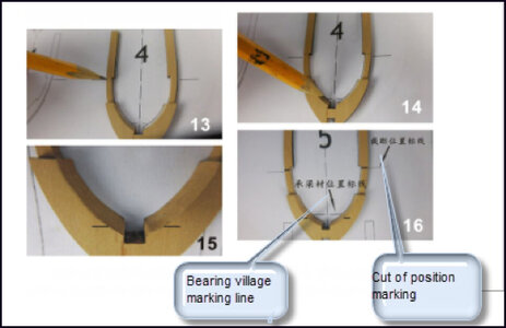
The manual states that you have to put 2 lines on the frames:
-at the top at the rejuvenation, the place where the frames have to be cut later to get the hull free of the jig;
-at the bottom the mark where the lower bearing beams should be placed.
A picture from the translated manual:
But if you want to fit the bearing beams neatly at the top and bottom, the frames on the inside, where the bearing beams are installed, has to be flat. After applying the spacers I did the first rough sanding and lost all marking lines again.
After installing the top bearing beams, the frames got their strength.
The inside has been further sanded so that the transitions of all frames are neatly flowing over the full width.
For that I used a strip of thin balsa veneer:
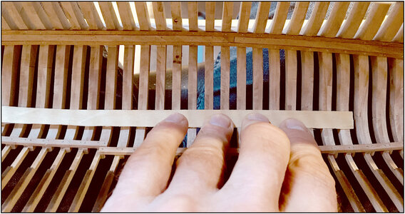
I laid it over several frames and then pushed with a little pressure, back and forth over the veneer with a few fingers. Then you feel exactly where a frames just sticks out above it or lies just below it.
This then marked:
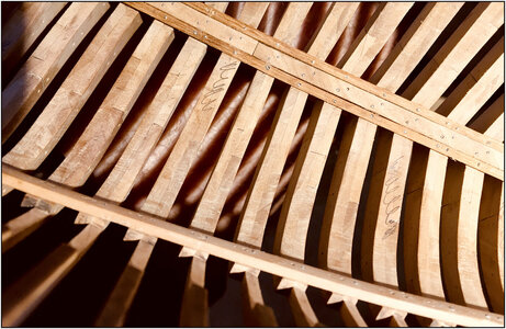
And back to sanding.
For sanding I made a block that has the curve of the inside of the hull:

With the added advantage that the frame that just protrudes slightly above, starts howling from the vibrations. A matter of sanding, feeling, sanding, until that frame becomes silent and all frames connect flush to each other.
Now I could start with the lower bearing beams.
Cutouts made on both sides, because they have to go over the sisters keelson up to the keelson in the middle:

Since the markings for their location were no longer present, I cut 5 frames from the drawings in the manual (18-23-28-33-38). These were placed against the relevant frames and the markings were taken over again.
Then the two bearing beams with the clamps fixed between the frames 13 and 43, taking into account the markings.
Because the extra step might have caused quite a few deviations, the horizontal position was checked by inserting long wooden (sate) skewers through the frames and let them rest on the beams:
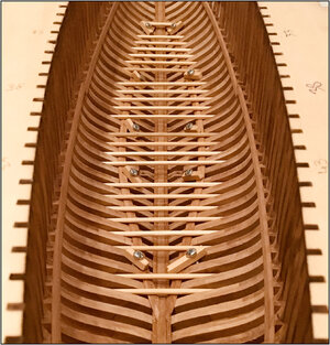
Of course after I also had the jig horizontal in width.
Doesn't look bad from the rear. With the remark that the skewers are not all equally straight:
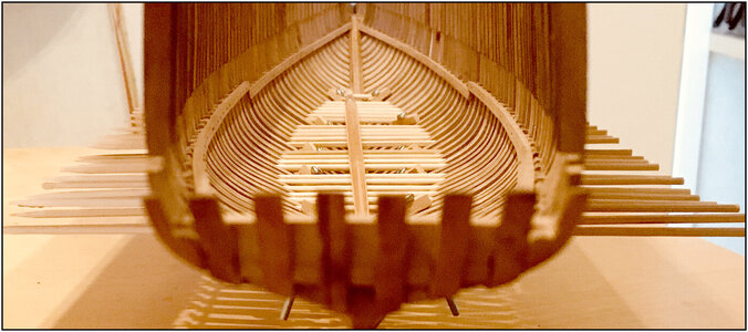
Put a long brush in the middle to give some pressure.
The average height of left and right is correct.
There are still a few imperfections that require some sanding.
And I can always make a galley out of it:
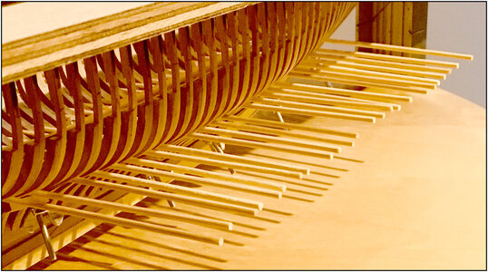
Then I can now mark the drill holes for the nails, start drilling holes, cut enough nails and mill them ......
And yes: mark the frames on the front/back after sanding and before installing!! Then theory and practice comes together again.
Regards, Peter
Also to give the non-BN-builders an insight into the manual, that theory and practice do not always go together and how I managed a little problem. Which might help other BN builders.
The manual states that you have to put 2 lines on the frames:
-at the top at the rejuvenation, the place where the frames have to be cut later to get the hull free of the jig;
-at the bottom the mark where the lower bearing beams should be placed.
A picture from the translated manual:

But if you want to fit the bearing beams neatly at the top and bottom, the frames on the inside, where the bearing beams are installed, has to be flat. After applying the spacers I did the first rough sanding and lost all marking lines again.
After installing the top bearing beams, the frames got their strength.
The inside has been further sanded so that the transitions of all frames are neatly flowing over the full width.
For that I used a strip of thin balsa veneer:

I laid it over several frames and then pushed with a little pressure, back and forth over the veneer with a few fingers. Then you feel exactly where a frames just sticks out above it or lies just below it.
This then marked:

And back to sanding.
For sanding I made a block that has the curve of the inside of the hull:

With the added advantage that the frame that just protrudes slightly above, starts howling from the vibrations. A matter of sanding, feeling, sanding, until that frame becomes silent and all frames connect flush to each other.
Now I could start with the lower bearing beams.
Cutouts made on both sides, because they have to go over the sisters keelson up to the keelson in the middle:

Since the markings for their location were no longer present, I cut 5 frames from the drawings in the manual (18-23-28-33-38). These were placed against the relevant frames and the markings were taken over again.
Then the two bearing beams with the clamps fixed between the frames 13 and 43, taking into account the markings.
Because the extra step might have caused quite a few deviations, the horizontal position was checked by inserting long wooden (sate) skewers through the frames and let them rest on the beams:

Of course after I also had the jig horizontal in width.
Doesn't look bad from the rear. With the remark that the skewers are not all equally straight:

Put a long brush in the middle to give some pressure.
The average height of left and right is correct.
There are still a few imperfections that require some sanding.
And I can always make a galley out of it:


Then I can now mark the drill holes for the nails, start drilling holes, cut enough nails and mill them ......
And yes: mark the frames on the front/back after sanding and before installing!! Then theory and practice comes together again.
Regards, Peter
Last edited:
- Joined
- Jan 9, 2020
- Messages
- 10,377
- Points
- 938

@Peter Voogt This is incredibly detailed work carried out by a mathematician cum perfectionist! Your advice is beyond valuable to all BN builders and what you have done is lay out the definitive method of ensuring symmetry and proper fitment. I can just hear those beams "moaning" in protest while being sanded - until - EXACTLY like you have said - they will go silent. But then ... anyone who finds this rare, just has to look at that Pocher Ducati and all will become crystal clear. Great, great work!
Good job of explaining, and pointing out the importance of sanding and leveling the inside of the frames. I actually used a file everywhere I could, and sandpaper for the rest!I'm working on the bearing beams for the lower floor. But before I can place them, a quick note.
Also to give the non-BN-builders an insight into the manual, that theory and practice do not always go together and how I managed a little problem. Which might help other BN builders.
The manual states that you have to put 2 lines on the frames:
-at the top at the rejuvenation, the place where the frames have to be cut later to get the hull free of the jig;
-at the bottom the mark where the lower bearing beams should be placed.
A picture from the translated manual:
View attachment 241482
But if you want to fit the bearing beams neatly at the top and bottom, the frames on the inside, where the bearing beams are installed, has to be flat. After applying the spacers I did the first rough sanding and lost all marking lines again.
After installing the top bearing beams, the frames got their strength.
The inside has been further sanded so that the transitions of all frames are neatly flowing over the full width.
For that I used a strip of thin balsa veneer:
View attachment 241483
I laid it over several frames and then pushed with a little pressure, back and forth over the veneer with a few fingers. Then you feel exactly where a frames just sticks out above it or lies just below it.
This then marked:
View attachment 241484
And back to sanding.
For sanding I made a block that has the curve of the inside of the hull:
View attachment 241485
With the added advantage that the frame that just protrudes slightly above, starts howling from the vibrations. A matter of sanding, feeling, sanding, until that frame becomes silent and all frames connect flush to each other.
Now I could start with the lower bearing beams.
Cutouts made on both sides, because they have to go over the sisters keelson up to the keelson in the middle:
View attachment 241489
Since the markings for their location were no longer present, I cut 5 frames from the drawings in the manual (18-23-28-33-38). These were placed against the relevant frames and the markings were taken over again.
Then the two bearing beams with the clamps fixed between the frames 13 and 43, taking into account the markings.
Because the extra step might have caused quite a few deviations, the horizontal position was checked by inserting long wooden (sate) skewers through the frames:
View attachment 241490
Of course after I also had the jig horizontal in width.
Doesn't look bad from the rear. With the remark that the skewers are not all equally straight:
View attachment 241491
Put a long brush in the middle to give some pressure.
The average height of left and right is correct.
There are still a few imperfections that require some sanding.
And I can always make a galley out of it:
View attachment 241492
Then I can now mark the drill holes for the nails, start drilling holes, cut enough nails and mill them ......
And yes: mark the frames on the front/back after sanding and before installing!! Then theory and practice vomes together again.
Regards, Peter
@Peter Voogt This is incredibly detailed work carried out by a mathematician cum perfectionist! Your advice is beyond valuable to all BN builders and what you have done is lay out the definitive method of ensuring symmetry and proper fitment. I can just hear those beams "moaning" in protest while being sanded - until - EXACTLY like you have said - they will go silent. But then ... anyone who finds this rare, just has to look at that Pocher Ducati and all will become crystal clear. Great, great work!
Thanxs Heinrich and Dean, for these nice words A little extra attention to the inside couldn't hurt. Especially because on one side comes also inner shelves as a wall.Good job of explaining, and pointing out the importance of sanding and leveling the inside of the frames. I actually used a file everywhere I could, and sandpaper for the rest!
Regards, Peter
Compliments are well deserved Peter!Thanxs Heinrich and Dean, for these nice words A little extra attention to the inside couldn't hurt. Especially because on one side comes also inner shelves as a wall.
Regards, Peter
I know you will build a very accurate and detailed ship! And I know you have good plans and ideas of how to embellish the kit, to be most likely one of the best examples yet! I am cheering you on, and your windlass motor will be ready soon! Then we must look at that steering mechanism!
Last edited:
Given the questions I got in a PM, this part of my previous post wasn't almost clear:
Since the markings for their location were no longer present, I cut 5 frames from the drawings in the manual (18-23-28-33-38). These were placed against the relevant frames and the markings were taken over again.
This is a picture of the drawing from the back parts of frame 23:
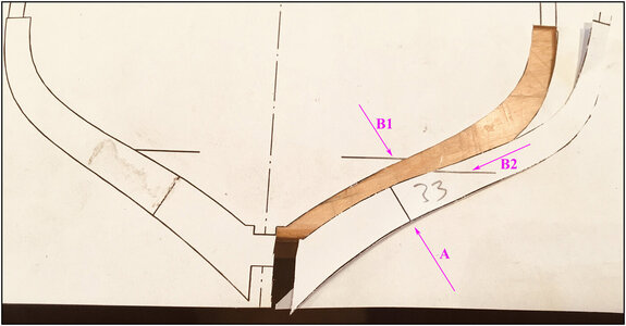
Arrow A points to the seam between the 2 parts on which the mold can be aligned later.
Arrow B1 points to the line that indicates the position where the bearing beam should be aligned. Arrow B2 is the continuing of that line on the template.
Then cut on the line. Luckily I didn't have to color within the lines.
The mold placed on the frame 23, the end against the keel and lined on the seam:
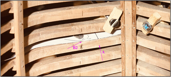
Arrow A points to the seam between the 2 parts of the back frame.
Arrow B2 to the end of the line for the position of the bearing beam. This position is marked on the frame.
I could also have made a mold of the front frame. Or be able to determine the position 'by eye' on the basis of both drawings.
(Yes, that bold on frame 21 has got a extra hit )
)
Regards, Peter
Since the markings for their location were no longer present, I cut 5 frames from the drawings in the manual (18-23-28-33-38). These were placed against the relevant frames and the markings were taken over again.
This is a picture of the drawing from the back parts of frame 23:

Arrow A points to the seam between the 2 parts on which the mold can be aligned later.
Arrow B1 points to the line that indicates the position where the bearing beam should be aligned. Arrow B2 is the continuing of that line on the template.
Then cut on the line. Luckily I didn't have to color within the lines.
The mold placed on the frame 23, the end against the keel and lined on the seam:

Arrow A points to the seam between the 2 parts of the back frame.
Arrow B2 to the end of the line for the position of the bearing beam. This position is marked on the frame.
I could also have made a mold of the front frame. Or be able to determine the position 'by eye' on the basis of both drawings.
(Yes, that bold on frame 21 has got a extra hit
Regards, Peter
Last edited:
The bottom bearing beams have been installed.
Here I have the starboard after glueing fixed with clamps and for a good distribution of the pressure on all frames, with the thick elastics:
And the dots of glue for the port side beam, just above the markers:
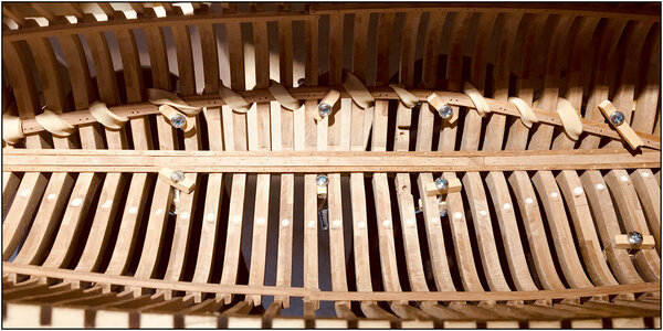
Both fixed and ready for drying several hours:
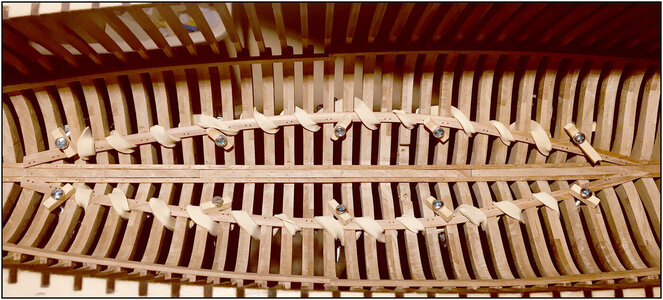
And the nails applied:
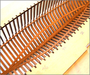
On this pictures I have illuminated the hull with a warmer light. This is what it may look like when a layer of presumably linseed oil as been applied.
The traditional (scrolling) picture:

My favorite view:
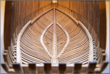
It looks like there is a kink in the low beams halfway through, but that has to do with the course of the hull. YQ has cleverly transferred that from the design to these parts. See the long 'standing' photo above for the nice flow. A big + for @yqmodel !
This photo from the side shows also the beautiful flow of these bearing beams.

What surprised me the most while working on the inside of the hull till now:
-how a few beams give the hull so much strength;
-that a cup-burr of around €2.00 is still sharp after around 560 nails.
4 (smaller) bearing beams to go.
Regards, Peter
Here I have the starboard after glueing fixed with clamps and for a good distribution of the pressure on all frames, with the thick elastics:
And the dots of glue for the port side beam, just above the markers:

Both fixed and ready for drying several hours:

And the nails applied:

On this pictures I have illuminated the hull with a warmer light. This is what it may look like when a layer of presumably linseed oil as been applied.
The traditional (scrolling) picture:

My favorite view:

It looks like there is a kink in the low beams halfway through, but that has to do with the course of the hull. YQ has cleverly transferred that from the design to these parts. See the long 'standing' photo above for the nice flow. A big + for @yqmodel !
This photo from the side shows also the beautiful flow of these bearing beams.

What surprised me the most while working on the inside of the hull till now:
-how a few beams give the hull so much strength;
-that a cup-burr of around €2.00 is still sharp after around 560 nails.
4 (smaller) bearing beams to go.
Regards, Peter
Last edited:
She's a real beauty! You're work is impeccable!The bottom bearing beams have been installed.
Here I have the starboard after glueing fixed with clamps and for a good distribution of the pressure on all frames, with the thick elastics:
And the dots of glue for the port side beam, just above the markers:
View attachment 241788
Both fixed and ready for drying several hours:
View attachment 241789
And the nails applied:
View attachment 241790
On this pictures I have illuminated the hull with a warmer light. This is what it may look like when a layer of presumably linseed oil as been applied.
The traditional (scrolling) picture:
View attachment 241791
And my favorite view:
View attachment 241792
It looks like there is a kink in the low beams halfway through, but that has to do with the course of the hull. YQ has cleverly transferred that from the design to these parts. See the long 'standing' photo above for the nice flow. A big + for @yqmodel !
This photo from the side shows also the beautiful flow of these bearing beams.
View attachment 241793
What surprised me the most while working on the inside of the hull till now:
-how a few beams give the hull so much strength;
-that a cup-burr of around €2.00 is still sharp after around 560 nails.
4 (smaller) bearing beams to go.
Regards, Peter
I had to look up that word, Dean. It was not in my vocabulary, till now: THANXS!She's a real beauty! You're work is impeccable!
Regards, Peter
Your care and detailing as you progress show the results. Very well done. RichThe bottom bearing beams have been installed.
Here I have the starboard after glueing fixed with clamps and for a good distribution of the pressure on all frames, with the thick elastics:
And the dots of glue for the port side beam, just above the markers:
View attachment 241788
Both fixed and ready for drying several hours:
View attachment 241789
And the nails applied:
View attachment 241790
On this pictures I have illuminated the hull with a warmer light. This is what it may look like when a layer of presumably linseed oil as been applied.
The traditional (scrolling) picture:
View attachment 241791
My favorite view:
View attachment 241792
It looks like there is a kink in the low beams halfway through, but that has to do with the course of the hull. YQ has cleverly transferred that from the design to these parts. See the long 'standing' photo above for the nice flow. A big + for @yqmodel !
This photo from the side shows also the beautiful flow of these bearing beams.
View attachment 241793
What surprised me the most while working on the inside of the hull till now:
-how a few beams give the hull so much strength;
-that a cup-burr of around €2.00 is still sharp after around 560 nails.
4 (smaller) bearing beams to go.
Regards, Peter
One of the immaculate works, Peter! Shine On You Crazy Diamond! 
- Joined
- Jan 9, 2020
- Messages
- 10,377
- Points
- 938

As I have said on the Dutch forum - brilliant work that redefines the concept of "symmetry". You mention linseed oil - you might want to take a look at what I have just achieved on a Pearwood model (actually I'm not 100% sure if it's Pearwood or Elsbeere) with a very special kind of tung oil. The slightly darker or "shinier" spots still indicate that the oil is in the process of penetrating.

This is a very rich finish tone. RichAs I have said on the Dutch forum - brilliant work that redefines the concept of "symmetry". You mention linseed oil - you might want to take a look at what I have just achieved on a Pearwood model (actually I'm not 100% sure if it's Pearwood or Elsbeere) with a very special kind of tung oil. The slightly darker or "shinier" spots still indicate that the oil is in the process of penetrating.
View attachment 241843
Thanxs for your kind words, Rich.Your care and detailing as you progress show the results. Very well done. Rich
Also new for my vocabulary: I feel flattered, Jim. For sure not Comfortably Numb.One of the immaculate works, Peter! Shine On You Crazy Diamond!
I learn a lot here at the SoS: both in terms of construction techniques and linguistically.
Heinrich, also for you: thanxs for your compliment.As I have said on the Dutch forum - brilliant work that redefines the concept of "symmetry". You mention linseed oil - you might want to take a look at what I have just achieved on a Pearwood model (actually I'm not 100% sure if it's Pearwood or Elsbeere) with a very special kind of tung oil. The slightly darker or "shinier" spots still indicate that the oil is in the process of penetrating.
View attachment 241843
First with a
Seriously: does the spots pulls back in its entirety or is that a point to keep an eye on with oil?
I like the matte look, what I prefer for my BN.
With a PS for you:
After the critical notes from us as builders, a compliment to YQ may also be in time.
Regards, Peter
- Joined
- Jan 9, 2020
- Messages
- 10,377
- Points
- 938

If the spots do not disappear after 8 hours, it means that the wood is saturated in that particular area. Then you just wipe the spot (actually it's a tiny pool of oil) away with a Kleenex. Voila! With this particular tung oil, the coats are applied in a very particular way. Rubbing the surface with a soft, lint-free cloth after application will increase the gloss while steel wool is often used between coats - I obviously chose not to.
Thanxs Heinrich,If the spots do not disappear after 8 hours, it means that the wood is saturated in that particular area. Then you just wipe the spot (actually it's a tiny pool of oil) away with a Kleenex. Voila! With this particular tung oil, the coats are applied in a very particular way. Rubbing the surface with a soft, lint-free cloth after application will increase the gloss while steel wool is often used between coats - I obviously chose not to.
I will do some tests on some spare plates of the frames. And will look further for Tung oil.
I still have plenty of time, because oiling is not yet on the agenda. There is still so much to do in and on the hull.
Regards, Peter
Hallo, Peter! (wow, I am speaking dutch already)... You may reconsider the timing for the oiling. Once you will put lower beams, it will be difficult to oil on some spots. I think some of those spots should be oiled sooner, but what do I know...I still have plenty of time, because oiling is not yet on the agenda. There is still so much to do in and on the hull.
- Joined
- Apr 20, 2020
- Messages
- 5,123
- Points
- 738

Dear PeterThe bottom bearing beams have been installed.
Here I have the starboard after glueing fixed with clamps and for a good distribution of the pressure on all frames, with the thick elastics:
And the dots of glue for the port side beam, just above the markers:
View attachment 241788
Both fixed and ready for drying several hours:
View attachment 241789
And the nails applied:
View attachment 241790
On this pictures I have illuminated the hull with a warmer light. This is what it may look like when a layer of presumably linseed oil as been applied.
The traditional (scrolling) picture:
View attachment 241791
My favorite view:
View attachment 241792
It looks like there is a kink in the low beams halfway through, but that has to do with the course of the hull. YQ has cleverly transferred that from the design to these parts. See the long 'standing' photo above for the nice flow. A big + for @yqmodel !
This photo from the side shows also the beautiful flow of these bearing beams.
View attachment 241793
What surprised me the most while working on the inside of the hull till now:
-how a few beams give the hull so much strength;
-that a cup-burr of around €2.00 is still sharp after around 560 nails.
4 (smaller) bearing beams to go.
Regards, Peter
she looks beautiful, you are doing fine job

Jim, you're right. I do have to think about which parts to treat at which stage of construction. To have in mind those spots and where I have to glue parts of planks. I have a general idea of my plans, but now I have to work out something in detail. Thanks for pushing me with the facts and to Set the Controls ......Hallo, Peter! (wow, I am speaking dutch already)... You may reconsider the timing for the oiling. Once you will put lower beams, it will be difficult to oil on some spots. I think some of those spots should be oiled sooner, but what do I know......Look around, choose your own ground

Hi Shota, thank you very much.Dear Peter
she looks beautiful, you are doing fine job

Regards, Peter

