- Home
- Forums
- Ships of Scale Group Builds and Projects
- Bluenose PoF Group Build
- Bluenose Group Build Logs
You are using an out of date browser. It may not display this or other websites correctly.
You should upgrade or use an alternative browser.
You should upgrade or use an alternative browser.
YUANQING BLUENOSE - Peter Voogt [COMPLETED BUILD]
- Thread starter Peter Voogt
- Start date
- Watchers 67
Yes, you will need another set of beams for the cabin deck. Looking forward to seeing it come to fruition!Thanxs Dean, for thinking along. I visualized the structures on the deck and adapted my plan to them. The stairs run from back to front and then lead to the cabin. There are also level differences visible in the drawings in The Saga, so with AL-FI in it, I think my plan will fit.
Regards, Peter
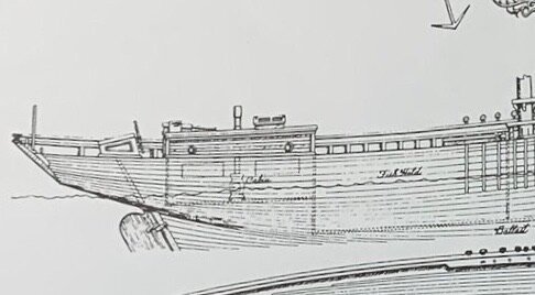
It looks like the far wall is at the end of the fish hold, which I assume would be at the end of the mid lower deck beams. You can use the deck sheet to help locate the walls, that will give you the perimeter of the cabin. I’m sure you have figured this out. Also the deck beams should line up and locate them.This drawing in The Saga is helping with my plan:
View attachment 246602
There will be an intermediate floor later. So storage underneath it.
I can line out that sub-floor, when the frames are planked on the inside.
Regards, Peter
Yep Dean, when I start with the deck beams, I can line up the inside walls. But hope I will get my wood for the inside hull planking soon.It looks like the far wall is at the end of the fish hold, which I assume would be at the end of the mid lower deck beams. You can use the deck sheet to help locate the walls, that will give you the perimeter of the cabin. I’m sure you have figured this out. Also the deck beams should line up and locate them.
Thanxs Heinrich. Fortunately, there is that drawing to give some direction. Hopefully that fits in with the rest of my plans.This is the first time in three days that I could access SOS. You have made great progress - the speculative investigations sure add to the suspense!
Regards, Peter
Before I can start customizing the deck beams, the most important thing now is to align the top of the bearing beam properly. Because they ensure that the deck beams are lying horizontally and have a nice course of the sheer in the deck.
As with the subfloor, I align it with the long toothpicks:
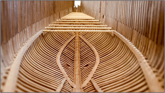
In the bow it is very tricky, because there they are close to each other. Every fraction of a mm already gives an oblique position, as shown here.
After several times sanding, re-inserting and fitting, sanding etc, finally a satisfactory result:
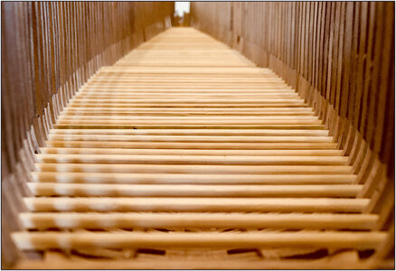
Still not easy to make a straight picture with the iPhone through the small opening at the back.
With the overview:
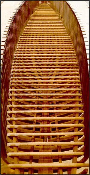
The next step is to prepare the clamps, shown in the drawing from the Saga (see post #372).
That was a while ago, but for a number of steps in the construction of the hull, I sometimes have to think a several steps ahead. And only later I can apply it.
I can, of course, omit that thinking ahead and only show it when the time has come. But I just want to show in this build-log how the whole process goes. (But I don't want to spoil everything either. )
)
The deck beams are locked between the clamps, lying on top the bearing beam.
This clamp comes just above the bearing beam and rests on the cams of the lower rear frame parts. So I included the flattening of the cams when aligning the bearing beams:
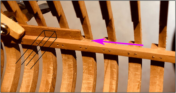
Once I have the deck beams in place, I can flatten the clamp to the correct height. So that later the deck will lie flat over it again. Because of the chamfering of the deck beams towards the bow and stern, the height of the clamp is not the same over the entire length.
Time for scratch building of the clamps.
Regards, Peter
As with the subfloor, I align it with the long toothpicks:

In the bow it is very tricky, because there they are close to each other. Every fraction of a mm already gives an oblique position, as shown here.
After several times sanding, re-inserting and fitting, sanding etc, finally a satisfactory result:

Still not easy to make a straight picture with the iPhone through the small opening at the back.
With the overview:

The next step is to prepare the clamps, shown in the drawing from the Saga (see post #372).
That was a while ago, but for a number of steps in the construction of the hull, I sometimes have to think a several steps ahead. And only later I can apply it.
I can, of course, omit that thinking ahead and only show it when the time has come. But I just want to show in this build-log how the whole process goes. (But I don't want to spoil everything either.
The deck beams are locked between the clamps, lying on top the bearing beam.
This clamp comes just above the bearing beam and rests on the cams of the lower rear frame parts. So I included the flattening of the cams when aligning the bearing beams:

Once I have the deck beams in place, I can flatten the clamp to the correct height. So that later the deck will lie flat over it again. Because of the chamfering of the deck beams towards the bow and stern, the height of the clamp is not the same over the entire length.
Time for scratch building of the clamps.
Regards, Peter
Last edited:
Thanxs Heinrich. Rotating the jig/hull to see the alignment from different sides, I saw with the (warm) spotlight several nice shifting shadow effects between all those frames, beams and sticks. Too much to post.WOW That color is incredible and the overall effect, stunning!
Regards, Peter
I think Peter is having as much fun taking pictures of his ship, as he is building it!WOW That color is incredible and the overall effect, stunning!
You are right, Dean. Photography is now also a hobby, which I have been able to apply professionally through my work. And in which, still in the analogue era, I was able to learn a lot about the technical aspects.I think Peter is having as much fun taking pictures of his ship, as he is building it!
1 picture tells more than 100 words. Fortunately, otherwise it would be veeeeerrrrrryyyyyyy long posts.
Regards, Peter
Last edited:
- Joined
- Apr 20, 2020
- Messages
- 5,140
- Points
- 738

Dear friendBefore I can start customizing the deck beams, the most important thing now is to align the top of the bearing beam properly. Because they ensure that the deck beams are lying horizontally and have a nice course of the sheer in the deck.
As with the subfloor, I align it with the long toothpicks:
View attachment 247051
In the bow it is very tricky, because there they are close to each other. Every fraction of a mm already gives an oblique position, as shown here.
After several times sanding, re-inserting and fitting, sanding etc, finally a satisfactory result:
View attachment 247052
Still not easy to make a straight picture with the iPhone through the small opening at the back.
With the overview:
View attachment 247053
The next step is to prepare the clamps, shown in the drawing from the Saga (see post #372).
That was a while ago, but for a number of steps in the construction of the hull, I sometimes have to think a several steps ahead. And only later I can apply it.
I can, of course, omit that thinking ahead and only show it when the time has come. But I just want to show in this build-log how the whole process goes. (But I don't want to spoil everything either.)
The deck beams are locked between the clamps, lying on top the bearing beam.
This clamp comes just above the bearing beam and rests on the cams of the lower rear frame parts. So I included the flattening of the cams when aligning the bearing beams:
View attachment 247054
Once I have the deck beams in place, I can flatten the clamp to the correct height. So that later the deck will lie flat over it again. Because of the chamfering of the deck beams towards the bow and stern, the height of the clamp is not the same over the entire length.
Time for scratch building of the clamps.
Regards, Peter
you are doing wonderful work, very accurate, the result is great


Thanxs for the compliment, Shota. I really appreciate that!Dear friend
you are doing wonderful work, very accurate, the result is great


Regards, Peter
From some strips from my stock started with the clamps in the front low part.
Just like the rest dry-fit secured with some clamps:
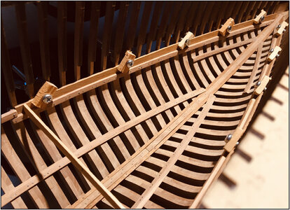
Looked up the deck beams in the kit. Unlike the lasered previous parts, these are CNC milled. Phoe, no laser carbon for a while!
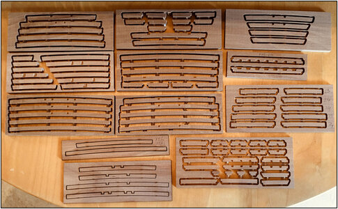
Because the deck beams need to be shortened and get the chamfer on the side of the clamp, I made a fitting lath from some other strips from my stock:
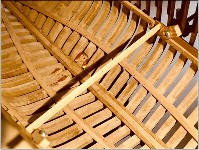
And when I work further forward, I can always shorten it a bit and use it again.
Marked the center on the fitting lath and the deck beam, placed on top of each other and the sides marked out:
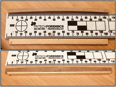
Now I could start using my recently purchased Japanese Kataba saw.
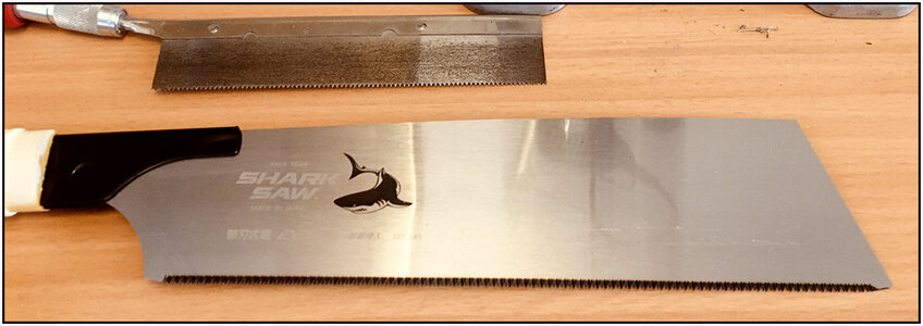
Length 225 mm / 8.86”, 0.4 mm / 0,0157 kerf, 21 tpi.
241
Then perhaps the question will be: "Why such a large saw for such small beams?"
The advantage of the length and width of the saw blade is that you can now clearly see both corners to be sawn and can make long strokes. And the teeth are 'on pull', in contrast to the usual saws that are 'on push'. That pushing would not work with the Japanese saw, because the blade is very flexible. (And perhaps I use it later for greater work)
The deck beams 1, 12, 18 and 26 just made:
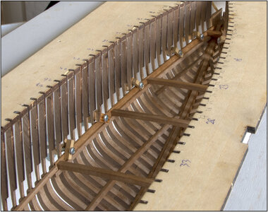
Also dry-fit and clamp between the 'clamps'.
A point to watch out for: deck beam 1 comes before frame 2! So if you have numbered the frames on the jig, a mistake is easily made. So just double numbered.
This is what it looks like from the outside:
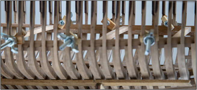
When the clamps are finally attached later, I fix them from the inside to the frames with nails.
I then fix the deck beams from the outside through the clamp with a nail.
Now I can fill the rest of the foredeck.
For now I don't have enough clamps for the 'clamps' on the aft deck. But I'm still busy with the foredeck and I hope that in the meantime my ordered wood will arrive.
Regards, Peter
Just like the rest dry-fit secured with some clamps:

Looked up the deck beams in the kit. Unlike the lasered previous parts, these are CNC milled. Phoe, no laser carbon for a while!

Because the deck beams need to be shortened and get the chamfer on the side of the clamp, I made a fitting lath from some other strips from my stock:

And when I work further forward, I can always shorten it a bit and use it again.
Marked the center on the fitting lath and the deck beam, placed on top of each other and the sides marked out:

Now I could start using my recently purchased Japanese Kataba saw.

Length 225 mm / 8.86”, 0.4 mm / 0,0157 kerf, 21 tpi.
241
Then perhaps the question will be: "Why such a large saw for such small beams?"
The advantage of the length and width of the saw blade is that you can now clearly see both corners to be sawn and can make long strokes. And the teeth are 'on pull', in contrast to the usual saws that are 'on push'. That pushing would not work with the Japanese saw, because the blade is very flexible. (And perhaps I use it later for greater work)
The deck beams 1, 12, 18 and 26 just made:

Also dry-fit and clamp between the 'clamps'.
A point to watch out for: deck beam 1 comes before frame 2! So if you have numbered the frames on the jig, a mistake is easily made. So just double numbered.
This is what it looks like from the outside:

When the clamps are finally attached later, I fix them from the inside to the frames with nails.
I then fix the deck beams from the outside through the clamp with a nail.
Now I can fill the rest of the foredeck.
For now I don't have enough clamps for the 'clamps' on the aft deck. But I'm still busy with the foredeck and I hope that in the meantime my ordered wood will arrive.
Regards, Peter
Last edited:
I realized you took out all of the lower crossbeams, as they were never installed permanently? Can’t you install them now?
Thanxs Shota.well done dear friend, it's looks great

Regards, Peter
Hi Dean. They where dry-fit. I can't install them until I've planked the (portside) inside of the frames. Starting at the (sisters) keelson and then up to the bearing beams of the lower floors. Then I can install them and then the planking further to the bearing beams of the deck.I realized you took out all of the lower crossbeams, as they were never installed permanently? Can’t you install them now?
I am waiting for delivery of the wood for the planking. Perhaps I will go to order by another shop.
Regards, Peter
Ok, that makes sense, I didn’t realize you were planking from the keelson up.Hi Dean. They where dry-fit. I can't install them until I've planked the (portside) inside of the frames. Starting at the (sisters) keelson and then up to the bearing beams of the lower floors. Then I can install them and then the planking further to the bearing beams of the deck.
I am waiting for delivery of the wood for the planking. Perhaps I will go to order by another shop.
Regards, Peter
The advantage of keeping a log is that you think about the text and the photos and read your post again afterwards.
Then I realized that with the 4 made deck beams, it allows me to mark and update the height of the clamp over the entire length:
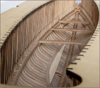
So now with the almost a flat connection at the top:
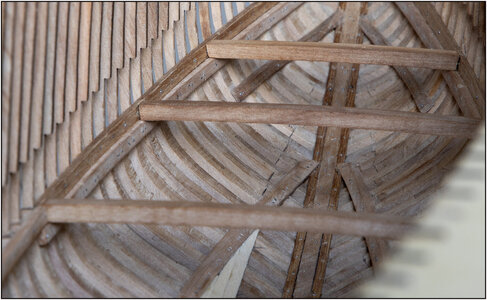
And attached to the frames with the nails.
When all the beams are installed, I make the final sanding.
In the meantime I found another shop on the internet that had some slats that I had been waiting for a while. Called for stock, ordered it and the next day I already had it at home.
So I could finally start with the inner wall ceiling of the hull.
In doing so, I proceeded from the directions on the drawing in The Saga, which stated:
"Ceiling, continued to 3" from sister keelsons." Converted to 1:72, that is about 12 mm / 0.47”.
Started with the first piece under the middle floor:
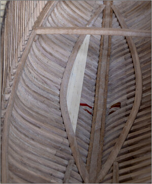
After installing the floor beams, I can do the rest upwards.
And the ceiling under the front floor:
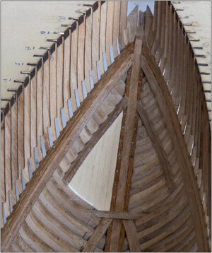
Here I closed it up to the keelson because it was also used as storage.
Both parts of the ceiling:
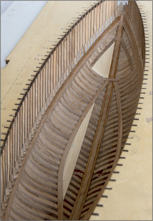
The trim of the top center piece, will later joins the front piece. But first the floor beams and the floor, because then I know how to make the connection between floor and the ceiling.
Now first see which parts I have to give the 1st protective layer before I can finally attach the floor beams for the lower floors. And that I can no longer reach.
Regards, Peter
Then I realized that with the 4 made deck beams, it allows me to mark and update the height of the clamp over the entire length:

So now with the almost a flat connection at the top:

And attached to the frames with the nails.
When all the beams are installed, I make the final sanding.
In the meantime I found another shop on the internet that had some slats that I had been waiting for a while. Called for stock, ordered it and the next day I already had it at home.
So I could finally start with the inner wall ceiling of the hull.
In doing so, I proceeded from the directions on the drawing in The Saga, which stated:
"Ceiling, continued to 3" from sister keelsons." Converted to 1:72, that is about 12 mm / 0.47”.
Started with the first piece under the middle floor:

After installing the floor beams, I can do the rest upwards.
And the ceiling under the front floor:

Here I closed it up to the keelson because it was also used as storage.
Both parts of the ceiling:

The trim of the top center piece, will later joins the front piece. But first the floor beams and the floor, because then I know how to make the connection between floor and the ceiling.
Now first see which parts I have to give the 1st protective layer before I can finally attach the floor beams for the lower floors. And that I can no longer reach.
Regards, Peter
One reason why the ceiling does not extend to the keelson is the application of the ballast. It is known that the ballast on the original BN consisted of pieces of pig / cast iron.
For that ballast I use the saved heads of the nails that I also use for the nails.
The space between 3 frames on the inside and outside is taped with tape that does not leave any glue residue afterwards.
A bundle of nail heads mixed with glue and worked them into the spaces:
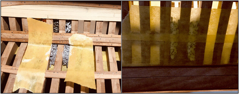
I use this glue. Thanks to @Jimsky Jim who advised it in his build-log. Wet it is white but dries transparent:

After removing the tape, this appeared:
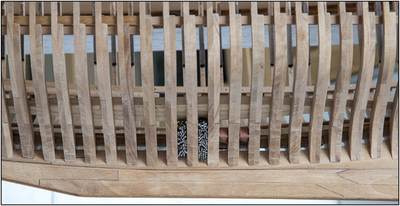
It lies nicely close to the frames:
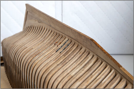
There comes planks on the port side, but on the starboard side it remains in sight.
You will continue to see this inside, but between the floor beams:
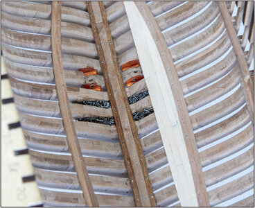
Perhaps the question: "Why only 2x2 spaces filled?"
1: Almost 900 nail heads is quite a lot, but in such a heap there is not much left.
2: This model is built as an open-yard-model. The site manager wants to show the technique and methodology that is used during this construction. The ballast is thus indicative of how it will be applied later.
Regards, Peter
For that ballast I use the saved heads of the nails that I also use for the nails.
The space between 3 frames on the inside and outside is taped with tape that does not leave any glue residue afterwards.
A bundle of nail heads mixed with glue and worked them into the spaces:

I use this glue. Thanks to @Jimsky Jim who advised it in his build-log. Wet it is white but dries transparent:

After removing the tape, this appeared:

It lies nicely close to the frames:

There comes planks on the port side, but on the starboard side it remains in sight.
You will continue to see this inside, but between the floor beams:

Perhaps the question: "Why only 2x2 spaces filled?"
1: Almost 900 nail heads is quite a lot, but in such a heap there is not much left.
2: This model is built as an open-yard-model. The site manager wants to show the technique and methodology that is used during this construction. The ballast is thus indicative of how it will be applied later.
Regards, Peter
Last edited:

