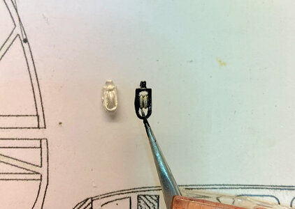
Model Airways Sopwith Camel

Here is a small update - as you know, I was able to find all the screws and hardware from the plastic container that opened. However, I still am not able to locate the remaining 3 springs. So, the springs are for the valve seats. I think the springs were just a miscount from the factory.

I decided to wrap my own springs and if I am successful, I will wrap all 24 so that there will be consistency in the material I am using which is stainless steel. The kit springs are some type of shiny material - not sure. But they will be replaced anyway.

Therefore, this is the progress so far. I ordered some stainless steel spring wire from Amazon and it arrived the other day - the price is excellent considering what I am getting. The spring wire comes all the way down to .2mm - and it is truly as fine as human hair. I might have to go up to .3mm

This is the link to the product.
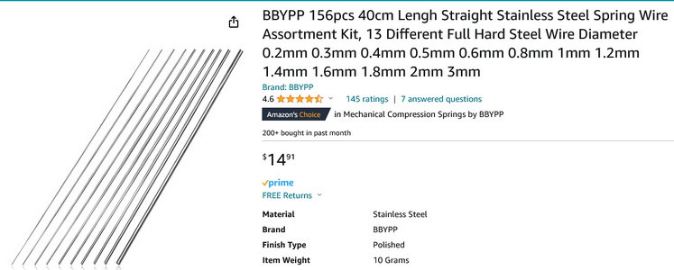
1703002417464.png

I did some research to see if there was an Equation to determine the mandrel diameter to wrap a spring GIVEN the Spring Diameter and the thickness of the wire you are using. Interesting, I did in fact find such a formula from a Google Search- but I have not tried this yet. So, if you wish to use this - you are welcome.

So, this is how the Equation works and I am going to plug in my own Spring Details. My Spring final diameter needs to be 3mm and the thickness of the wire in this case, I will use .25mm. The equation will have real-life values plugged in, but for now, let's see what happens.


Solve for a Spring Diameter of 3mm and a Stainless Steel Wire thickness is .25mm

Equation:

Dm= kD - d

where:
Dm is the diameter of the mandrel,
k is the diameter coefficient,
D is the final diameter of the spring, measured from the center of the wire (not the outer or the inner spring diameter).
d is the diameter of the wire.

The value of “X” is not listed, but first, we have to determine the Spring index to plug this into the formula:
X = D/d
Therefore 3mm / .25 mm = 12
Spring Index value “X” = 12

Next, determine the diameter coefficient of “k
k = -0.01245 (x) + 0.98425
k= (-0.01245 x 12) + 0.98425
k = -.1494 + 0.98425
k = 0.83485

Lastly, we can find the diameter of the spring (Dm or the Diameter of the Mandrel we need)
Dm = kD – d
Dm
= (0.83485 x 3mm) - .25mm
Dm = 2.50455 - .25

The diameter of the Mandrel will be 2.25mm

I have not made this Spring as of this post so far. When I do, I will report the results and see how accurate this equation is.
 
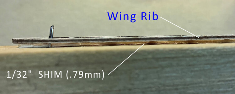
So much for the math lesson. This is an example from the manual on how to build up the Wing Ribs. A simple jig is constructed so that the 1/32 x 3/32 Rib CAPS will be CENTERED on the Ribs. The thickness of the Ribs are 1/32" - therefore the jig will allow for 1/32" overhang on each side of the rib.

wing-rib-jig-02.jpg


View from the side
wing-rib-jig-01.jpg


wing-ribs-sample-01.jpg
 
So, I got a little ambitious and I decided to create a spreadsheet that will automatically calculate the final diameter of the Mandrel or Drill Rod you will use to make the spring. The length is up to you. This only calculates the spring's final diameter based on the diameter and the wire size.

Try it out.

The only values you need to enter (in RED) are the width of the spring you need and the size of the wire.
 

Attachments

  • Spring-Calculator.xlsx
    11.1 KB · Views: 5
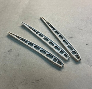
Most of the Ribs are repetitive - the only difference is the size and some cut-outs are different. Below, I am demonstrating one particular style of RIB due to the cavity that is cut out - this is a way that I found to keep the tip of the Rib Cavity from crushing while applying pressure on the clips while drying.


ribs02.jpg


One side is glued

ribs01.jpg

ribs03.jpg


FInal

ribs04.jpg[/B]
 
Last edited:
Yes, Paul, they ARE very fragile - I have not actually measured the length, but guessing they are about 3 inches long and maybe at best 3/8 wide. The thickness is 1/32"

The Ribs on the far right side of the picture are the most fragile as near the rear of the rib are these small square openings which makes the rib even more fragile. It is really important to have the Cap strips pre bent as close to shape as you can not to put stress on the parts. Even though the jig is critical, you still have to hold both the cap strip and the rib with tweezers - then take small clamps to hold. I use CA glue with an accelerator to accomplish this. Trying to get that RIb right down the middle of the Cap Strip is what you are wanting to accomplish - thats the goal.

It follows the old saying idiom "to hold your mouth right" to make them !!! LOL
 
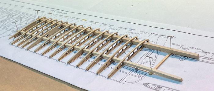
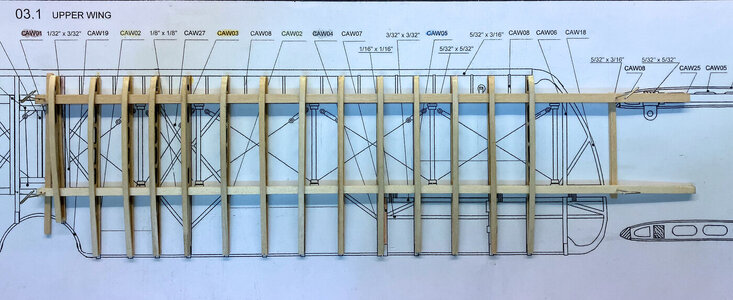
For some reason, the angled view looks like the spars are floating (towards the right side) and not lined up - but that is not the case. Everything is touching and lying correctly. I think the camera lens is doing some strange things.

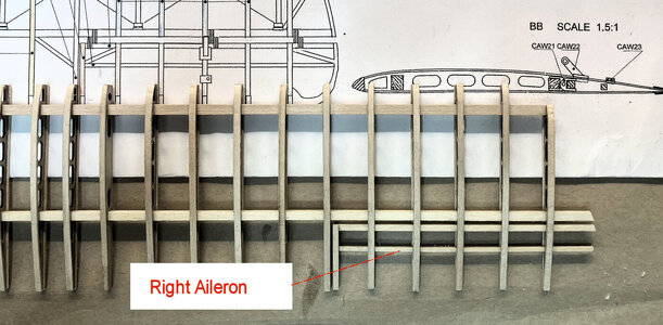
At any rate, here is the latest of one wing (right side). I admit that it took a while to make sure I had the correct Ribs in the proper place as it is very easy to get them misarranged. The strangest part that took a little figuring out at first is that the last 4 ribs even though are ONE PIECE - the Aileron "TIP" will be cut FREE and that was a little confusing - as I had to read further into the instructions before that is even mentioned.

ribs07.jpg


ribs08.jpg
 
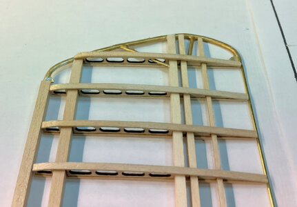
Now it is time to add one last-end Rib. The fore spar at the end has to taper down to fit into the "slot" of the last Rib. I have to admit that it took several times of reading the instructions to catch on to what to do. One of the illustrations on a few pages over gave a hint of the taper.

ribs10.jpg


ribs11.jpg
 
Time for the Ailerons.

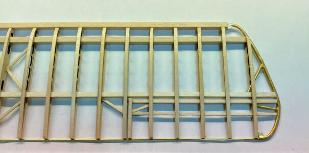
The first image shows the right side done.

ribs12.jpg


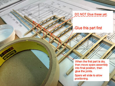
This shows the steps to make the process easier. Glue the small Aileron CAP on first and let dry. DO NOT glue the other joints. When the CAP is dry, then the entire Aileron-spar assembly will slide into position, and then you can glue.

ribs13.jpg
 
Hi Donnie, It’s all looking good, an interesting build. As you noticed Santa left me the AL version, it was your log that inspired me to add the Sopwith Camel to my wish list, it shows that build logs do get noticed and give inspiration to others. I don’t know yet wether to thank or curse you but time will tell
 
Hi Ken,
thank you for viewing the log - I will tune into your AL version - and it will be interesting to see the differences. I forgot about the AL version.
 
Thank you all for the likes !

Well, this is dry-fitting the Britannia End pieces. It took a considerable amount of time to get them formed. I saw some discrepancies in the Box Art, instructions,
and other research about how the Metal pieces interface with the upper and lower spars. I just did what I thought was the best and looked more to life mechanically that is - but what do I know about aircraft anyway :)

wing-caps-02.jpg


wing-caps-01.jpg
 
I almost forgot to mention that the front spars have to be in horizontal alignment - to do this, as you see I stood the wing on end and sanded back and forth until all the leading edges were straight. Then the wing is flipped the other way and the trailing edges were now sanded straight and flush.

ribs14.jpg
 
So, I took Dean's advice (of viewing his SWC thread) and this is the result of about a solid hour of trying to dress up the pulley. This is as good as it gets unless it is made from scratch which I will not do. The pulley itself will be painted brass or left as is. I also forgot to take a pic of the side view - that's coming up soon when it is mounted.

Before and After is quite obvious. Thank goodness for now, I only have to do one more. :rolleyes:

wing-pulleys-01.jpg
 
Back
Top