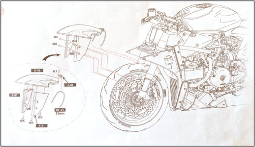
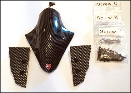
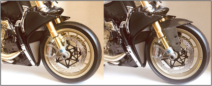
I am speechless - so very life-like - unbelieveable !!!
-

Win a Free Custom Engraved Brass Coin!!!
As a way to introduce our brass coins to the community, we will raffle off a free coin during the month of August. Follow link ABOVE for instructions for entering.
-

PRE-ORDER SHIPS IN SCALE TODAY!
The beloved Ships in Scale Magazine is back and charting a new course for 2026!
Discover new skills, new techniques, and new inspirations in every issue.
NOTE THAT OUR FIRST ISSUE WILL BE JAN/FEB 2026
- Home
- Forums
- Ships of Scale Build Logs
- Super Detailing Static Models / Other Genres
- Super Detailing Static Models
You are using an out of date browser. It may not display this or other websites correctly.
You should upgrade or use an alternative browser.
You should upgrade or use an alternative browser.
Pocher 1:4 Ducati Panigale S ‘Anniversario’ + ‘Final Edition
You are right, Donnie. It is a pleasure to work on The Duc. Some items are better lookalike than the first Duc. Pocher had improved this kit. But the bolts for Paul Koo made a big plus.I am speechless - so very life-like - unbelieveable !!!
Regards, Peter
Chapter 20:
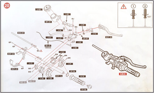
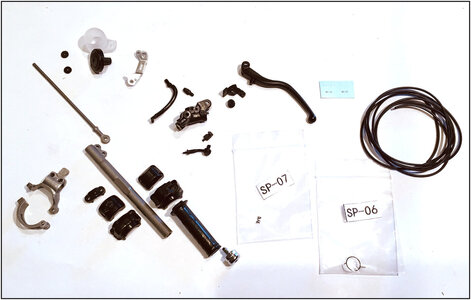
Right Handlebar with Brake:
All the parts. With 2 tiny spring.
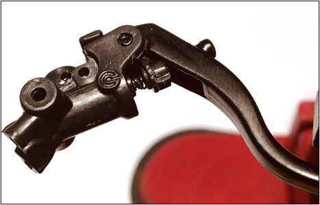
The parts for the brake lever and cylinder, with the tiny spring, fitted together:
The throttle can be rotated and is loaded with a spring.
From the Paul Koo manual:

Fitted together:
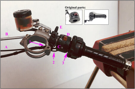
With the decals and the extra’s:
-most of the bolds where from the Paul Koo kit;
-1: cable for the brake sensor on the brake pump;
-2: cable for the starter switch;
-3: cable for the throttle control.
And:
-A: brake hose;
-B: steering damper rod;
-C: started button;
-D: switch lever;
-E: bleeder valve.
Also here the end of the bar painted black and the switch lever red.
And the reservoir cup filled with flued. I had to think for a moment how I would do that with this one. Because there are 2 mounting holes in the bottom and sealing both equally is not possible. The cap is screwed on from below.
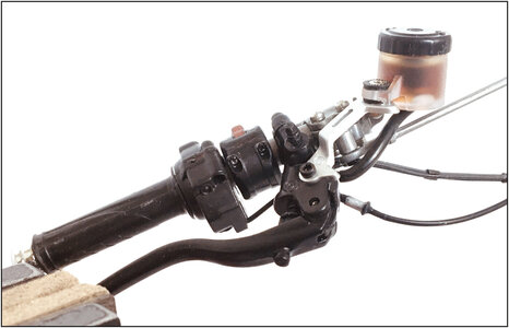
Seen from the other (front) side:
Regards, Peter

Right Handlebar with Brake:
All the parts. With 2 tiny spring.

The parts for the brake lever and cylinder, with the tiny spring, fitted together:

The throttle can be rotated and is loaded with a spring.
From the Paul Koo manual:

Fitted together:

With the decals and the extra’s:
-most of the bolds where from the Paul Koo kit;
-1: cable for the brake sensor on the brake pump;
-2: cable for the starter switch;
-3: cable for the throttle control.
And:
-A: brake hose;
-B: steering damper rod;
-C: started button;
-D: switch lever;
-E: bleeder valve.
Also here the end of the bar painted black and the switch lever red.
And the reservoir cup filled with flued. I had to think for a moment how I would do that with this one. Because there are 2 mounting holes in the bottom and sealing both equally is not possible. The cap is screwed on from below.
Seen from the other (front) side:

Regards, Peter
Chapter 21:
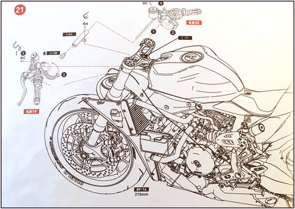
Fitting both handlebars and the Steering Damper.
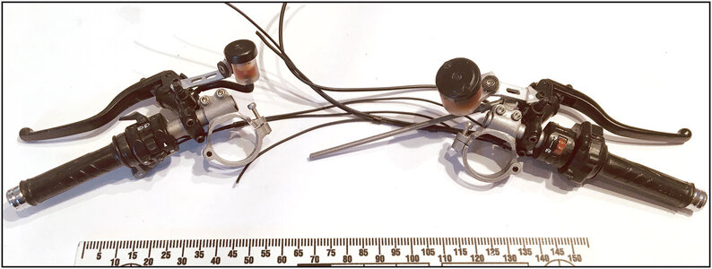
The 2 bars:
The reservoir of the clutch does not stand well. That was also with the previous model.
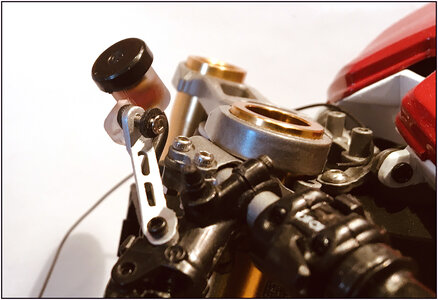
Unscrewed and cut away a position cam.
The left handlebar fitted:
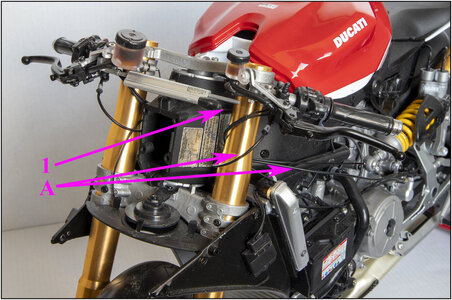
Extra:
-1: the Damper got its sensor cable. The damper works speed dependent. Plus a Paul Koo Ohlins decal.
And:
-A: the hose for the clutch fitted.
- the reservoir in a better position. The bike is now on the garage bar. When it stands on his wheels, its coming more straight.
The working clutch lever, because of the little spring:
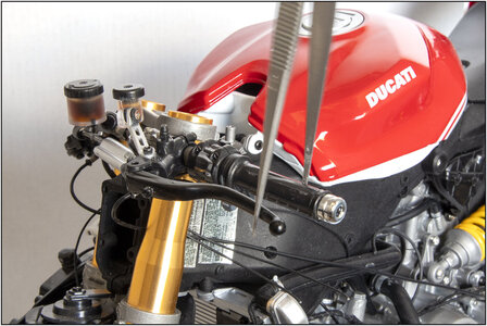
I forgot the picture with the lever in its free position.
The right handlebar, with the working brake lever:
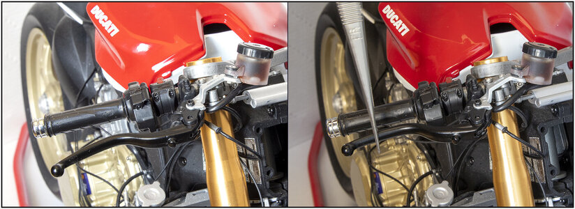
And the working throttle. I put a arrow marker on the handle to show begin and end position:

The view on both handles when you stand beside the bike:
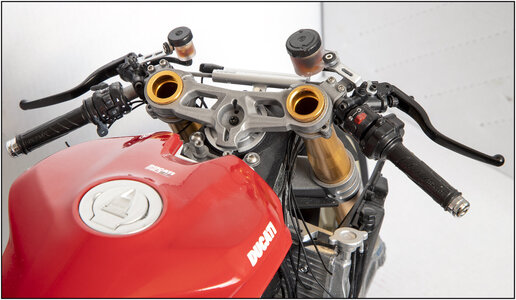
And now it looks more as a bike:
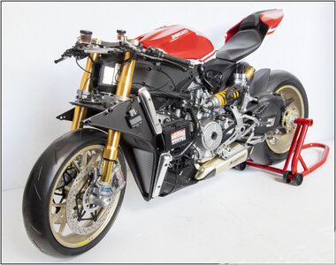
But not ready for a test drive. A lot of hoses, tubes and cables must be fitted. And on the right side the brake pedal.
Regards, Peter

Fitting both handlebars and the Steering Damper.
The 2 bars:

The reservoir of the clutch does not stand well. That was also with the previous model.

Unscrewed and cut away a position cam.
The left handlebar fitted:

Extra:
-1: the Damper got its sensor cable. The damper works speed dependent. Plus a Paul Koo Ohlins decal.
And:
-A: the hose for the clutch fitted.
- the reservoir in a better position. The bike is now on the garage bar. When it stands on his wheels, its coming more straight.
The working clutch lever, because of the little spring:

I forgot the picture with the lever in its free position.
The right handlebar, with the working brake lever:

And the working throttle. I put a arrow marker on the handle to show begin and end position:

The view on both handles when you stand beside the bike:

And now it looks more as a bike:

But not ready for a test drive. A lot of hoses, tubes and cables must be fitted. And on the right side the brake pedal.
Regards, Peter
Last edited:
Chapter 22:
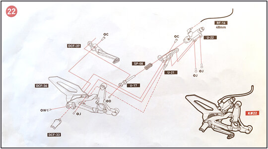 Right Footpeg / Brake Lever / Heel Guard
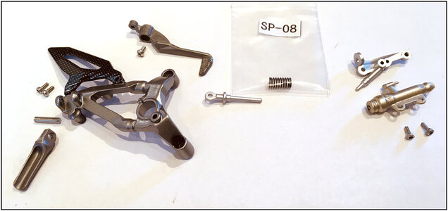
The collected parts and Paul Koo bolts:
The parts fitted together:
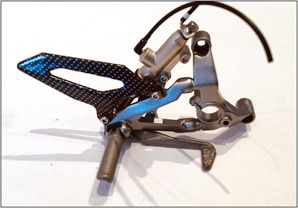
Extra the banjo plug, clamps on the hose, painting some parts black and the Paul Koo bolts.
On the back side you can see the working brake lever:
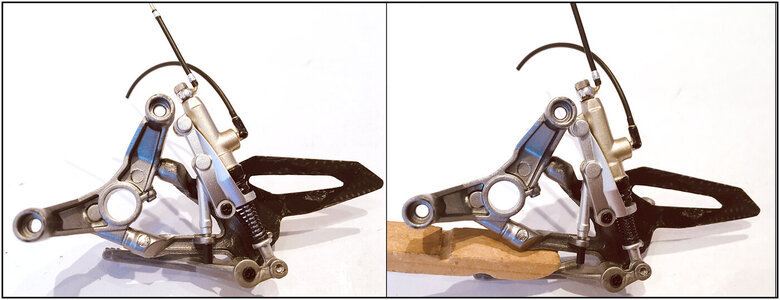
On the rotating points, which are not in view on the bike, you can see the black Philips bolts from the kit.
If those bolts were also mounted in the front, the look would be significant different.
The installing on the bike is later. Some brake hoses must be modified.
regards, Peter
 Right Footpeg / Brake Lever / Heel Guard
The collected parts and Paul Koo bolts:

The parts fitted together:

Extra the banjo plug, clamps on the hose, painting some parts black and the Paul Koo bolts.
On the back side you can see the working brake lever:

On the rotating points, which are not in view on the bike, you can see the black Philips bolts from the kit.
If those bolts were also mounted in the front, the look would be significant different.
The installing on the bike is later. Some brake hoses must be modified.
regards, Peter
Last edited:
Hi Peter,
Amazing build, do the parts "just go together" or is there a fair bit of work needed before assembly?
Cheers,
Stephen.
Amazing build, do the parts "just go together" or is there a fair bit of work needed before assembly?
Cheers,
Stephen.
Hi Stephen, thanxs for your likes, reply and interest.Hi Peter,
Amazing build, do the parts "just go together" or is there a fair bit of work needed before assembly?
Cheers,
Stephen.
In principle, you can screw everything together, straight out the box.
With filing some small edges from the parts wich you have to cut out the platic frames. The metal parts are largely neatly finished and provided with paint.
By the build of the first Duc, 4 years ago, 2 bolts broke off by me. Because the hole was not deep or wide enough. But most can be prevent by always adding a small tip of oil to the bolt. And pre screw in the hole in question, and with a little resistance, do not twist with force (what I did
In this construction, I chose to use the taps from the set that Paul Koo can supply with his hardware kit.
When you do the super detailing ..... then there is ‘a fair bit of work needed before assembling’
Regards, Peter
In the last chapter I was forgotten to show the last added extra detail on the brake light switch:
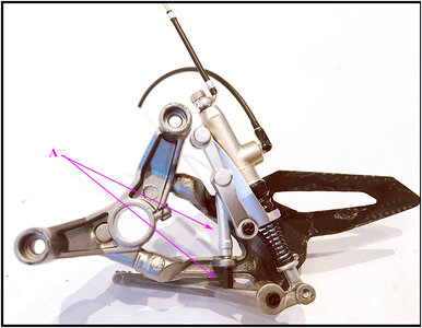
A: the rear brake switch.
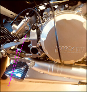
A: the brake light switch cable.
Chapter 23:
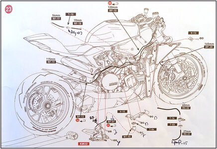
Installing Right Footpeg Bracket and all the Brake Hoses.
Some parts were already installed in previous chapters, because you could do better then.
Just 3 left for this chapter:
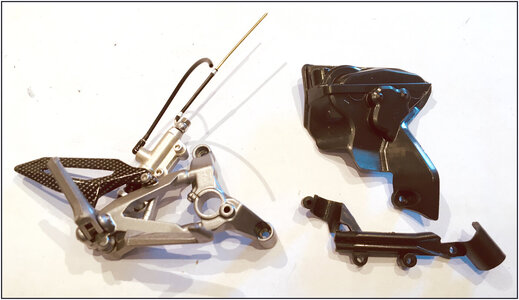
But the amount of work is no less.
Paul Koo advises to adapt the brake hoses to the original. There are pieces of metal tube in 2 places.
I pre installed the cover to adjust the 2 pieces of tube in the rear brake hoses:
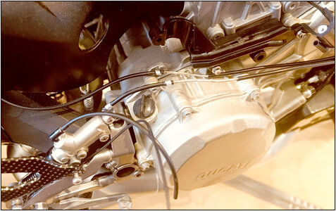
With the hose clamps of course.
At first a overall view from all the work in this chapter:
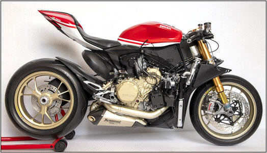
But there are so many details, I show them in 2 separate pictures with indications of what is where.
The rear part:
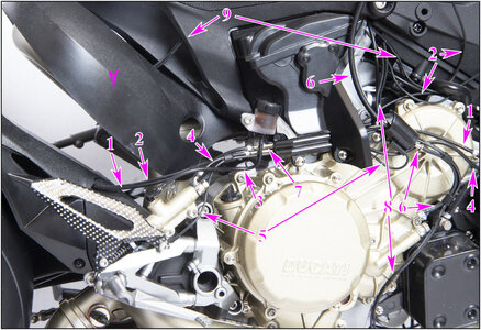
1: brake hose from rear brake caliper banjo to ABS-unit with metal section brake tube;
2: ABS-sensor cable from rear wheel to right electric panel;
3: brake hose from brake master cylinder to bottom of brake fluid reservoir;
4: brake hose from brake master cylinder to ABS unit;
5: brake light switch cable via connector to the electric panel;
6: oil pressure hose via switch to electric panel;
7: metal sections brake hose;
8: Lambda probe oxygen sensor cables from front cylinder tube to electric panel;
9: Lambda probe oxygen sensor cables from back cylinder tube to electric panel;
On the picture below:
10: brake hose from front brake caliper banjo to ABS-unit with metal section brake tube;
11: brake hose from front brake handle to ABS unit.
Finally installed the tube cover and the engine side cover.
With the same numbers, the front part:
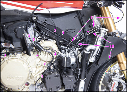
The other hoses were installed in other chapters.
The electric cables are connected in chapter 26 and 27.
And a picture from a different perspective:
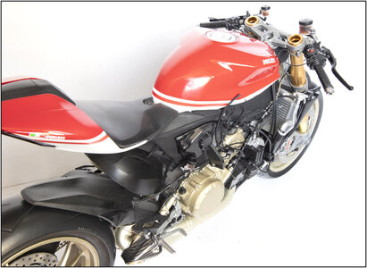
Regards, Peter

A: the rear brake switch.

A: the brake light switch cable.
Chapter 23:

Installing Right Footpeg Bracket and all the Brake Hoses.
Some parts were already installed in previous chapters, because you could do better then.
Just 3 left for this chapter:

But the amount of work is no less.
Paul Koo advises to adapt the brake hoses to the original. There are pieces of metal tube in 2 places.
I pre installed the cover to adjust the 2 pieces of tube in the rear brake hoses:

With the hose clamps of course.
At first a overall view from all the work in this chapter:

But there are so many details, I show them in 2 separate pictures with indications of what is where.
The rear part:

1: brake hose from rear brake caliper banjo to ABS-unit with metal section brake tube;
2: ABS-sensor cable from rear wheel to right electric panel;
3: brake hose from brake master cylinder to bottom of brake fluid reservoir;
4: brake hose from brake master cylinder to ABS unit;
5: brake light switch cable via connector to the electric panel;
6: oil pressure hose via switch to electric panel;
7: metal sections brake hose;
8: Lambda probe oxygen sensor cables from front cylinder tube to electric panel;
9: Lambda probe oxygen sensor cables from back cylinder tube to electric panel;
On the picture below:
10: brake hose from front brake caliper banjo to ABS-unit with metal section brake tube;
11: brake hose from front brake handle to ABS unit.
Finally installed the tube cover and the engine side cover.
With the same numbers, the front part:

The other hoses were installed in other chapters.
The electric cables are connected in chapter 26 and 27.
And a picture from a different perspective:

Regards, Peter
- Joined
- Jun 2, 2021
- Messages
- 36
- Points
- 48

Pocher…..definition = Long Haul, challenging, wow factor, accomplishment! Your build, attention to detail and clean approach is most excellent. I have not built any of their new kits. But the older ones….many. The prices are staggering now! I am working on probably my last Pocher Project. The Alfa Spyder Touring. Paul Koo, great individual. Looking forward to more.
Rick
Rick
Hi Rick,Pocher…..definition = Long Haul, challenging, wow factor, accomplishment! Your build, attention to detail and clean approach is most excellent. I have not built any of their new kits. But the older ones….many. The prices are staggering now! I am working on probably my last Pocher Project. The Alfa Spyder Touring. Paul Koo, great individual. Looking forward to more.
Rick
Thanxs for your kind words and compliments. I had the Alfa Spider also on my list, but the Bluenose came passing by. So I now divided the time between the Duc and the BN.
Regards, Peter
Chapter 25:
This chapter is in the manual divided in 4 parts. So first 25-1:
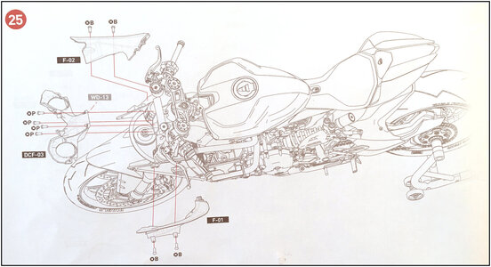
Front Airbox Intake + covers.
The parts:
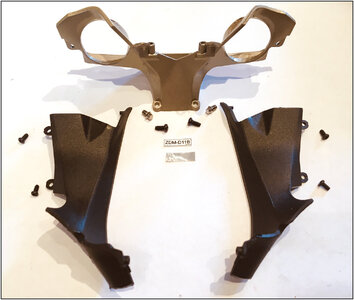
With the correct decal from Paul Koo and the metal-look surface.
Fitted on the Duc:
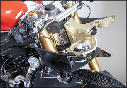
The holes for the 2 hex-bolds on the top of the airbox intake, has to be tappad to 2.5 mm.
Advise for Paul Koo: To fit the bolds on the under side of the 2 covers (blue arrows), you have to cut them shorter. Because the holes are very shallow. I have drilled them deeper and tapped them.
Regards, Peter
This chapter is in the manual divided in 4 parts. So first 25-1:

Front Airbox Intake + covers.
The parts:

With the correct decal from Paul Koo and the metal-look surface.
Fitted on the Duc:

The holes for the 2 hex-bolds on the top of the airbox intake, has to be tappad to 2.5 mm.
Advise for Paul Koo: To fit the bolds on the under side of the 2 covers (blue arrows), you have to cut them shorter. Because the holes are very shallow. I have drilled them deeper and tapped them.
Regards, Peter
Last edited:
Thanks Rick.You are knocking it out the ball park. Keep it up.
Rick
Steady working to the finish. But still a lot to do.
Regards, Peter
Before I went on, the horn has to be wired:
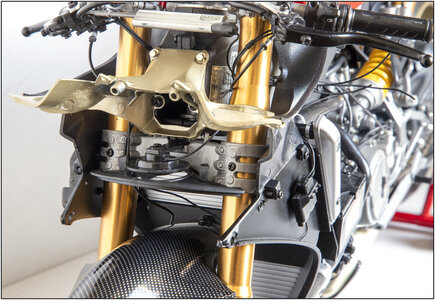
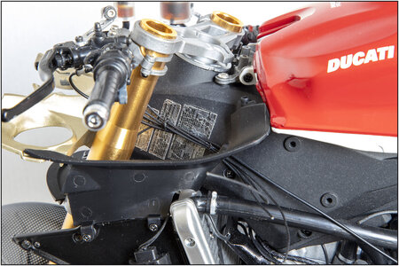
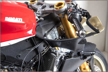
Then I could start with collecting all the wires to guide them neatly through the fairing covers.
On the left:
On the right:
And to get an impression of my (temporary) photo studio:
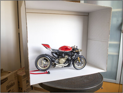
The inside of the cover box of the Pocher kit. Also good for a nice white-balance by adjusting the pictures.
Regards, Peter

Then I could start with collecting all the wires to guide them neatly through the fairing covers.
On the left:

On the right:

And to get an impression of my (temporary) photo studio:

The inside of the cover box of the Pocher kit. Also good for a nice white-balance by adjusting the pictures.
Regards, Peter
Chapter 25-2:
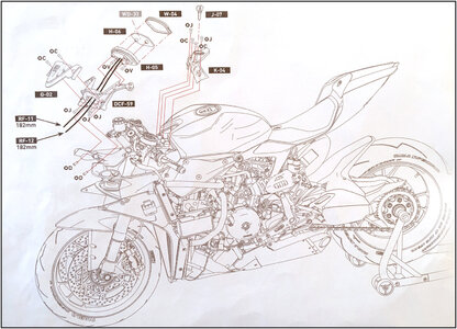
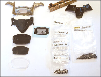
Instrument Cluster + Front Tank Cover + Ignition Switch.
The parts:
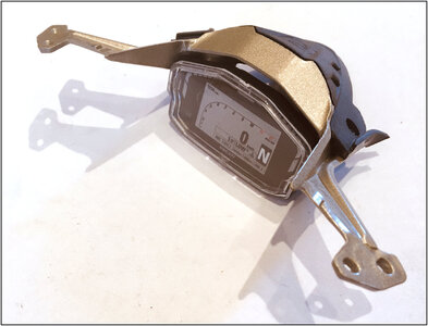
The Instrument Cluster fitted together:
And on the Duc:
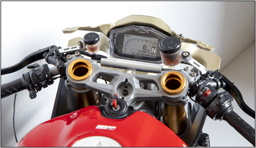
The Keyhole painted alu and the Key some Ducati-red.
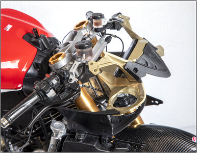
Amazing how tightly the parts fit together. It is quite a complex construction.
That was also the last metal parts. We are now on 5.4 kg.
Regards, Peter

Instrument Cluster + Front Tank Cover + Ignition Switch.
The parts:

The Instrument Cluster fitted together:

And on the Duc:

The Keyhole painted alu and the Key some Ducati-red.

Amazing how tightly the parts fit together. It is quite a complex construction.
That was also the last metal parts. We are now on 5.4 kg.
Regards, Peter
Last edited:
Chapter 25-3:
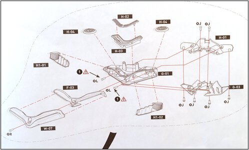
The Headlight unit.
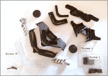
The parts:
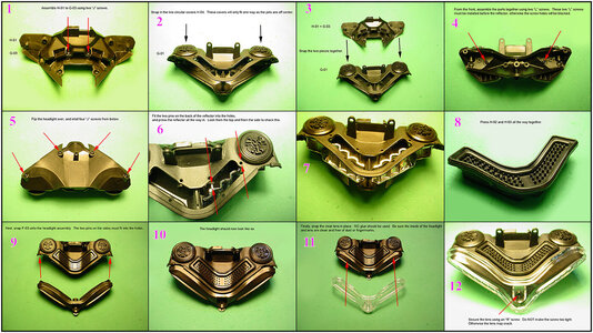
It's important to fit the parts in the right order together. Paul Koo has on his DVD a extra manual for the basic assembly. Here some pictures together from the different stept:
With this result:
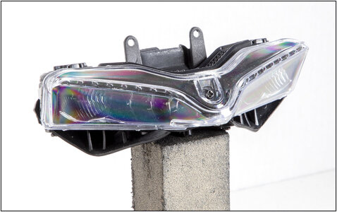
With under the glass the air intake with channels to the air-box.
On the back side, the channels comes together:
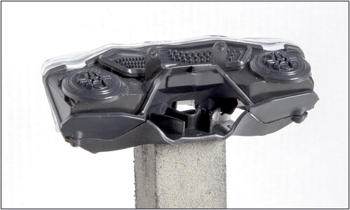
Regards, Peter

The Headlight unit.
The parts:

It's important to fit the parts in the right order together. Paul Koo has on his DVD a extra manual for the basic assembly. Here some pictures together from the different stept:

With this result:

With under the glass the air intake with channels to the air-box.
On the back side, the channels comes together:

Regards, Peter
Chapter 25-4:
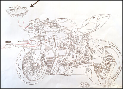
Assembling the Light Unit and the bottom trim plate.
Only 2 parts to compleet this chapter 25:
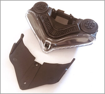
In the Pocher manual, this placement is done separately. First the unit, then the cover. But then you can hardly reach the middle bolt in the back of the cover plate. Then the front wheel is blocks your hand and screwdriver. Paul Koo puts the 2 parts together first and then places them both at the same time. That is then just as well fitting, measuring, turning and sliding/push into place:
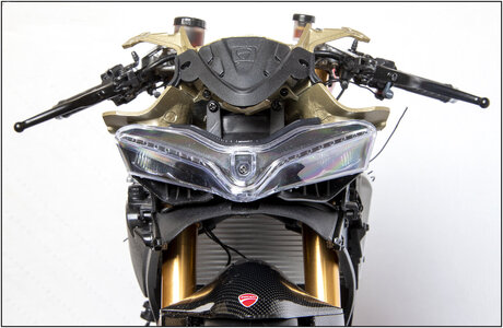
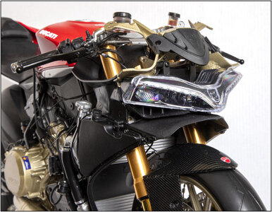
The 'state of affairs' from different points of view.
Right in front:
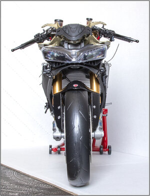
A real Bully. Active on the front:
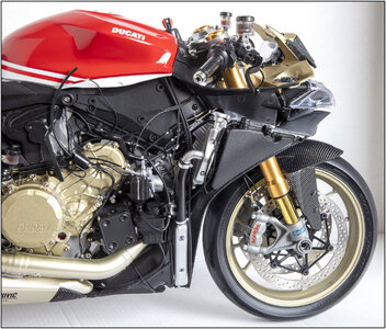
And a overview:
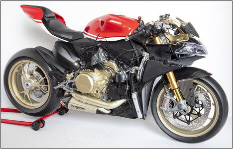
In the next 2 chapters, all the electrics are mounted on the panels on either side of the bike.
I first sit down and make a plan to get all the wiring in the right place.
But Paul Koo's manual is very helpful. He takes you step by step through this whole process with clear pictures.
Regards, Peter

Assembling the Light Unit and the bottom trim plate.
Only 2 parts to compleet this chapter 25:

In the Pocher manual, this placement is done separately. First the unit, then the cover. But then you can hardly reach the middle bolt in the back of the cover plate. Then the front wheel is blocks your hand and screwdriver. Paul Koo puts the 2 parts together first and then places them both at the same time. That is then just as well fitting, measuring, turning and sliding/push into place:


The 'state of affairs' from different points of view.
Right in front:

A real Bully. Active on the front:

And a overview:

In the next 2 chapters, all the electrics are mounted on the panels on either side of the bike.
I first sit down and make a plan to get all the wiring in the right place.
But Paul Koo's manual is very helpful. He takes you step by step through this whole process with clear pictures.
Regards, Peter
Last edited:
Chapter 26:
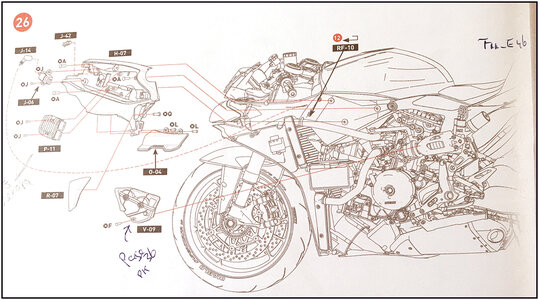
Left Hand Electrical Panel.
From the Pocher-kit, only one wire must be attached: RF-10. Thats the wire to the spark plug of the front cilinder, attached there in chapter 12.
The parts:
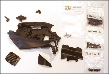
A lot of the extra added electrical wires comes together in and on this part of the bike. And are connected to the various components.
It is a little bit complex, but Paul Koo added a nice overview picture on his DVD:
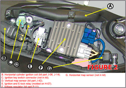
It is from an original Panigale where Paul Koo signed his information.
What can I tell more …….
Here the wires added to the components in 3 stages:

On the picture in the middle, you see on the left side the ’painters crepe tape’. I made it mat black with a permanent marker. Cut small strips of 3 mm to imitate the ‘cloth tape’ around a bundle of wires.
The picture on the right is from Paul Koo. I forgot to take a picture myself.
The panel, components and wires all fitted together:
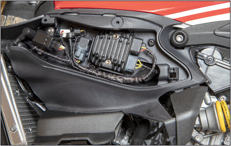
Most of it is done using 2 tweezers. But a thin strip of tape sticks to everything..... relax....... take your time.....
Some parts of the components are painted grey or made from white Evergreen.
With a picture of the completed left side of the bike, before the fairing is attached.
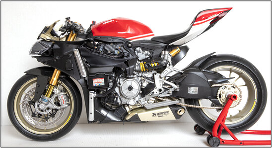
Up to the right electrical wires
Regards, Peter

Left Hand Electrical Panel.
From the Pocher-kit, only one wire must be attached: RF-10. Thats the wire to the spark plug of the front cilinder, attached there in chapter 12.
The parts:

A lot of the extra added electrical wires comes together in and on this part of the bike. And are connected to the various components.
It is a little bit complex, but Paul Koo added a nice overview picture on his DVD:

It is from an original Panigale where Paul Koo signed his information.
What can I tell more …….
Here the wires added to the components in 3 stages:

On the picture in the middle, you see on the left side the ’painters crepe tape’. I made it mat black with a permanent marker. Cut small strips of 3 mm to imitate the ‘cloth tape’ around a bundle of wires.
The picture on the right is from Paul Koo. I forgot to take a picture myself.
The panel, components and wires all fitted together:

Most of it is done using 2 tweezers. But a thin strip of tape sticks to everything..... relax....... take your time.....
Some parts of the components are painted grey or made from white Evergreen.
With a picture of the completed left side of the bike, before the fairing is attached.

Up to the right electrical wires
Regards, Peter
Last edited:
- Joined
- Apr 20, 2020
- Messages
- 6,211
- Points
- 738

amazing, well doneChapter 26:
View attachment 243494
Left Hand Electrical Panel.
From the Pocher-kit, only one wire must be attached: RF-10. Thats the wire to the spark plug of the rear cilinder, attached there in chapter 12.
The parts:
View attachment 243495
A lot of the extra added electrical wires comes together in and on this part of the bike. And are connected to the various components.
It is a little bit complex, but Paul Koo added a nice overview picture on his DVD:
View attachment 243496
It is from an original Panigale where Paul Koo signed his information.
What can I tell more …….
Here the wires added to the components in 3 stages:
View attachment 243498
On the picture in the middle, you see on the left side the ’painters crepe tape’. I made it mat black with a permanent marker. Cut small strips of 3 mm to imitate the ‘cloth tape’ around a bundle of wires.
The picture on the right is from Paul Koo. I forgot to take a picture myself.
The panel, components and wires all fitted together:
View attachment 243499
Most of it is done using 2 tweezers. But a thin strip of tape sticks to everything..... relax....... take your time.....
Some parts of the components are painted grey or made from white Evergreen.
With a picture of the completed left side of the bike, before the fairing is attached.
View attachment 243500
Up to the right electrical wires
Regards, Peter


