- Joined
- Dec 1, 2016
- Messages
- 6,241
- Points
- 728

LINING OFF THE HULL

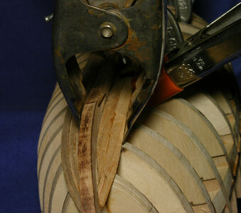
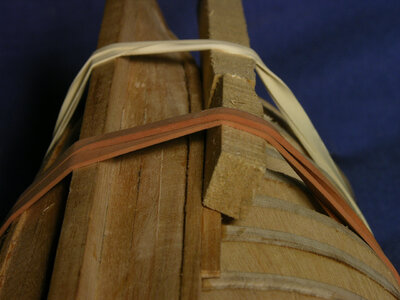
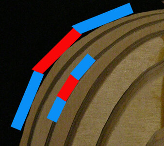
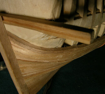
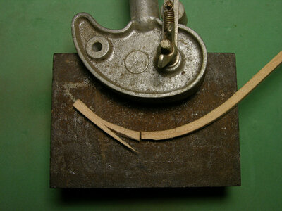
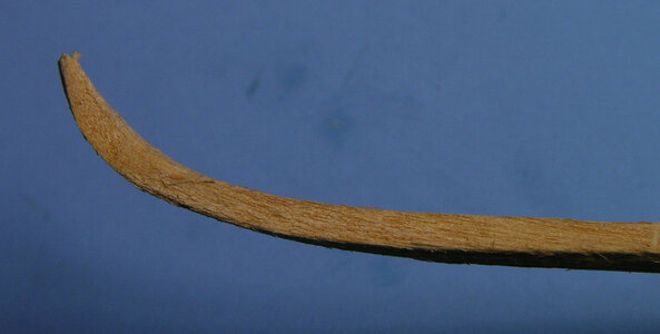
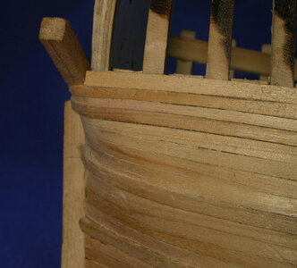
It is very common for kits to provide planking material unsuitable for the purpose, thus causing a number of problems for the model builder. Every commercial wood has its properties some are suitable for bending while others are not. Some common problems are, providing wood not suitable for bending, dry wood and providing planking material far to thin. Thinly milled wood will reach a certain point when it looses its strength and it breaks before it bends. Taking a look at the photo, the plank is bent and twisted from horizontal to vertical within a length of 6 inches. There were no heated plank bending tools used, nor was the wood soaked in water, the bend was done dry and cold. The bending and twisting was accomplished because, first the correct type of wood is used and second, notice the thickness, its much thicker material than usually provided in double planked kits. Actually the thickness is to the correct scale of a 3inch thick bottom plank. The last point is dry wood, you will find furniture and cabinet makers all require wood dry to a low 6% moisture, some wood workers will tell you that is too dry while other say no. As wood dries it becomes brittle so a kit sitting in a warehouse for a year will dry out the thin planking to a point it becomes so brittle it snaps when you try to bend it. An example of this is to take a dry twig and break it, it will not bend but it will snap in half, now take a green twig and do the same, you will find the green twig will bend, even be difficult to break. Even if you soak the dry twig in water it still will not have the same bending properties as a green twig. Somewhere between the dry and green twigs the perfect moisture content is used in planking a model. For this project the same wood used for the waterways is used to plank the hull. The Willow has been slowly seasoned in a solar kiln and not flash dried in heated commercial kiln. The wood is seasoned to a moisture content of from 12 to 15% keeping the wood flexible and preventing it from becoming brittle. There is a concern expressed by some model builders planking with a moisture content above 6% will cause the wood planking to shrink and you will have gaps between your planks. Black Willow was selected because while seasoning it has a large shrinkage but once seasoned and it looses it high moisture content it becomes very stable. The wood also does not split or check very easy. Lastly willow has an excellent ability to take glue and finishes to a smooth surface. Wood will move ever so slightly due to humidity in the air but not enough to notice, and it will not leave ugly gaps between your planking.
Before we actually get into the job of planking there are a couple issues to cover concerning caulking and fasteners. These you should decide on before you start the job.
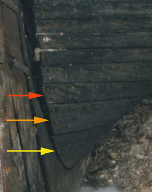
The Matthew is painted and any planking spikes may have been counter sunk and filled over. The black arrows are pointing to the barely visible heads of spikes. What can be seen are the caulk lines between the planks.
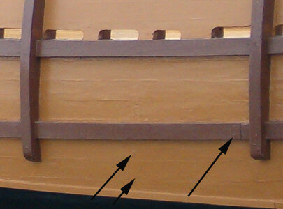
Model builders will go the extra steps and show caulking on the decks but not on the hull, it’s up to you, the builder, if you want to show caulking or not on the hull
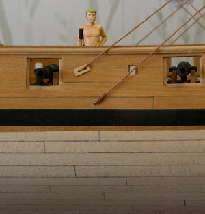
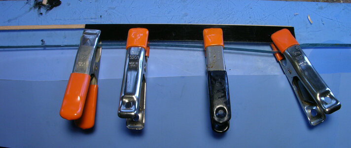
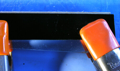
On this model the edges of the planks were darkened to simulate caulking, making every plank stand out. There are a few ways to create the caulking. One method is to darken the edges with a marking pen, which you would have to test to be sure the pen does not bleed into the wood and give you a fuzzy line. Another method is to use a soft lead pencil and darken the edges. With the use of a pencil the caulk lines will not be perfectly even and will tend to fade in and out. This does give a realistic appearance. By standing the planks on edge and gluing them to a sheet of black paper then cutting them apart will give you a perfectly even caulk seam. To produce a subtle appearance simply space the planks ever so slightly apart and allow the glue to ooze up between the planks.
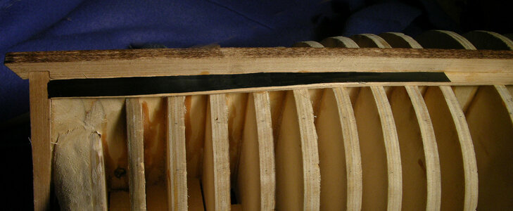
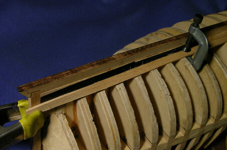
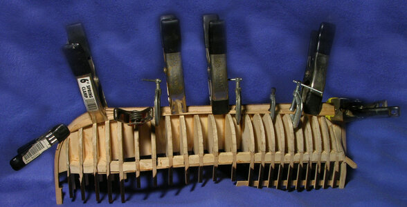
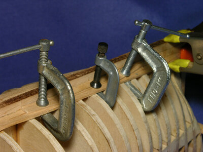
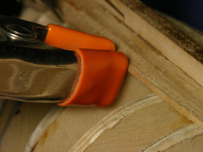
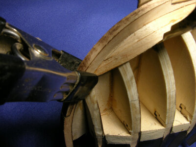
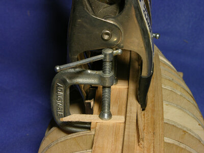
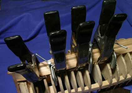
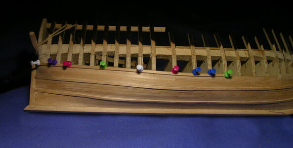
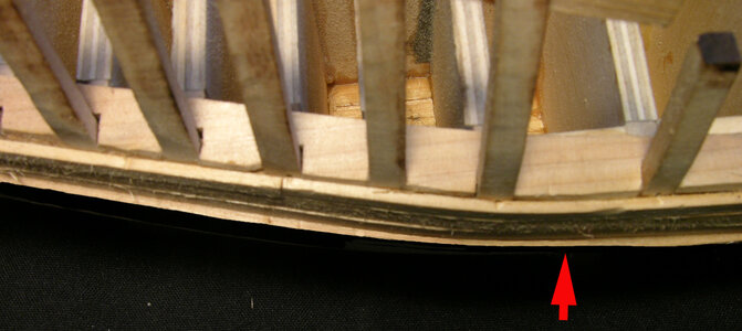
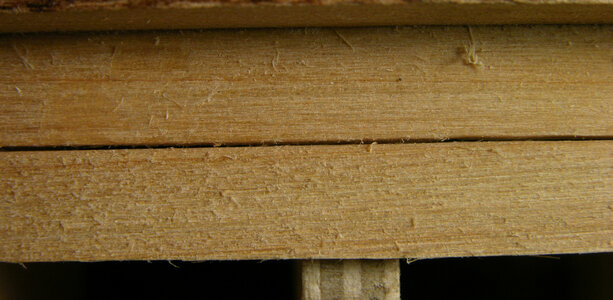
In the first photo the planks are set apart allowing several methods for showing the caulking. One is to leave the gap and allow it to fill in with whatever finish you intend on using, wipe the seams with a mixture of colored glue, or fill the seams with graphite paste mixture. This method is a little difficult to maintain an even gap between the planking because as the planks are glued to the hull they require clamping which may cause the planks to shift.
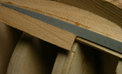
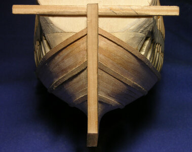
In the second photo the planking is set tight against each other. As you decide how to handle the caulking remember your at ¼ scale and at that size the caulking is so small it would be a very faint line.
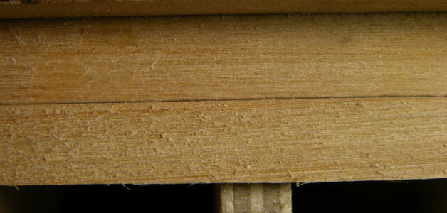
Caulking comes down to art vs. realism, you can exaggerate the caulking slightly so the viewer can see the individual planking and show off the craftsmanship of placing every plank. Also to demonstrate how the hull is built using planking and caulking to make the hull watertight. Or push the planking tight and leave only a hint of caulking.
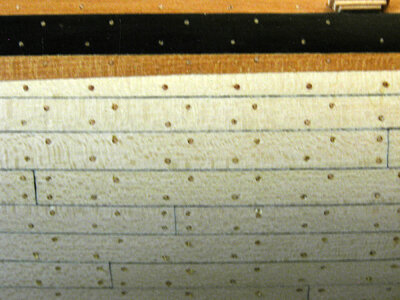
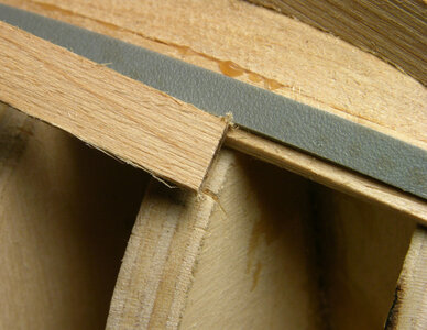
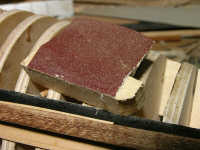
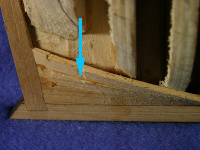
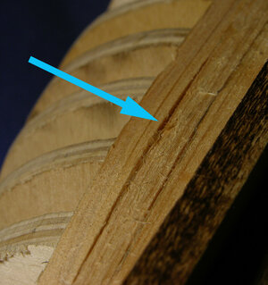
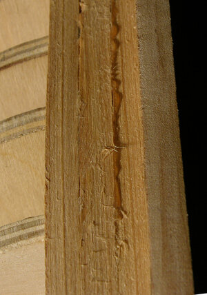
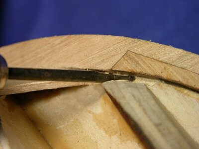
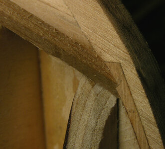
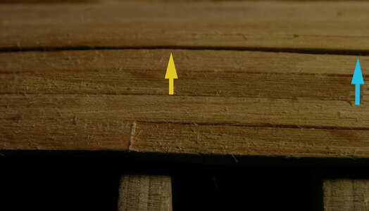
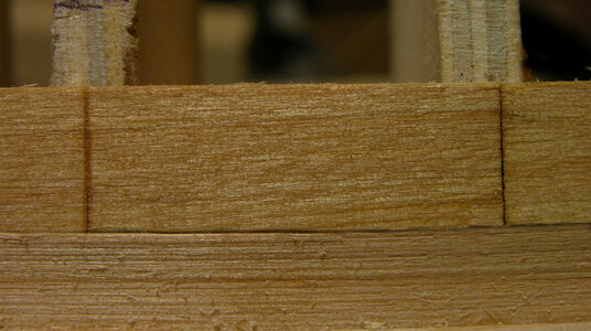
Finally the length of the planks used is something to consider. By planking the hull in one long strip makes bending and twisting of the plank easier. A quick and simple example of this is to hold a piece of planking with you hands about 3 inches apart, then twist and bend. Now hold a plank in your hands 12 inches apart and twist and bend. Its much easier to bend a long plank because the stress is spread over the length of the plank. Seventy foot planks were a little difficult to obtain in real life and even if the were handling them would be a big problem. The longest planks used were thirty foot with an average of 18 to 22 feet and down to just a few feet. One way to show the butt ends of planking is to cut a shallow seam into the plank. You can’t go to deep or the plank will snap at the cut. In the last photo is a fake butt cut into the plank and to the right is an actual butt joint. To the average viewer the difference may not be noticed. To anyone who has built a model ship and planked a hull can tell the difference between the two. The cut butts have to be done after the hull is given its final sanding or you will sand away the line.
Now we come to a debated issue that has been with ship modeling for many years, the treenail or wooden pegs used in ship building. On one side of the issue are those who feel using oversized and or contrasting treenails detracts from the model giving it the appearance of chicken pox. While on the other side there are those who like the look and feel it lend an element of authenticity to the construction of the model.
In most cases like the Matthew the hulls were painted and the fasteners didn’t show. Where hulls were not painted the fasteners were counter sunk and covered with either a wooden plug or a putty. On the realism side of the issue the fasteners were small and when reduced to ¼ scale they would disappear or be nothing more than a pin prick.
This is another issue where art vs. realism and it comes down to the model builders and what they want to show or demonstrate in their portrayal of a model of a wooden ship.
Leaving the final decision up to the builder all that can be done is to present the facts and the real thing and how to show the fasteners on a model, allowing the builder to choose.
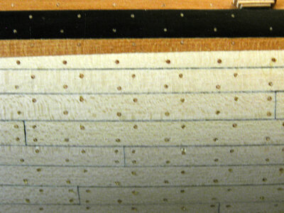
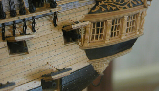
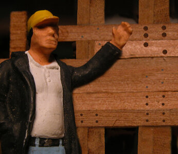
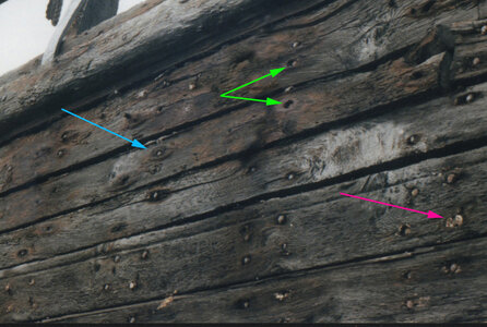
The only example we have for the time period of the Mathew for fastening planking to the hull is the Mary Rose. This ship used wooden trunnels which ran all the way through the outer planking through the frame and ceiling planking. The outer ends were counter sunk and plugged with a resin or tar. Butt ends of the hull planking of the Mary Rose used iron spikes. Over time iron spikes replaced the wood treenails all together. In the above photo is a close up of a shipwreck of about 1840 here we see the use of iron spikes, the green arrows show the same methods employed back when the Mary rose was built. The iron spikes were counter sunk and the red arrow shows the remains of a putty used to cover the spike. In the photo it looks as if the spikes are above the surface of the planking. Actually the wood plank is worn down as you can see by the area around the spike shown by the blue arrow. This shipwreck has sistered frames and the spike pattern shows two spikes in each half of the frame producing a pattern of four spikes per frame. The Matthew was not sister framed so the pattern most likely would be two fasteners per frame. To add treenails or not is the question each model shipwright will have to decide for themselves. Lets examine the choices, a planking spike measured 5/8 diameter and a wood treenail measured one inch. At ¼ scale a planking spike would be about .012 and a wood treenail .020. The ¼ scale plastic figure is showing different sizes of fasteners. The top large fasteners are the size of the little brass nails available from hobby supply dealers. These measure .025 to .030 if you drive the nail into the plank and snip off the heads. A true to scale iron spike would look like the examples in the center while the bottom examples are showing a wooden treenail at about 1 ¼ diameter.
The traditional method for adding treenails is the use bamboo or hardwood pulled through a draw plate. Alternatives would be to use the bristles from paint brushes, whisk brooms, push brooms, wall paper brushes or anything with bristles. Another materials are copper, brass or silver wire or plastic rods available in many sizes.
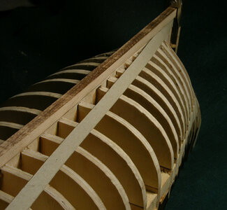
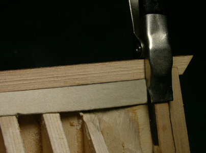
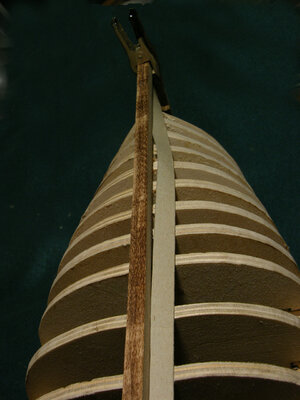
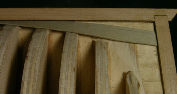
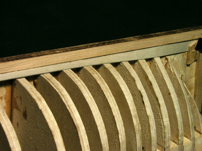
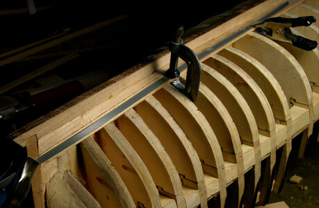
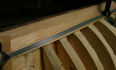
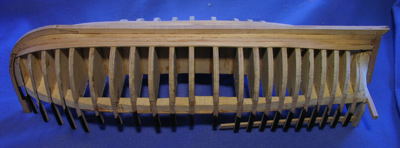
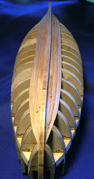
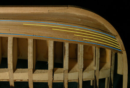
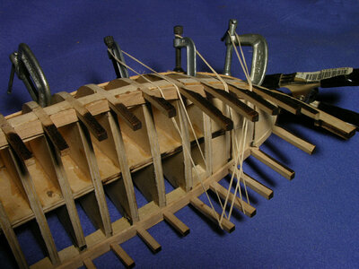
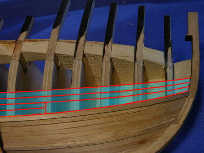
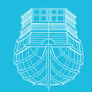
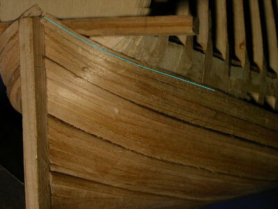
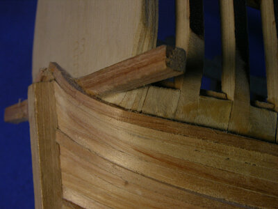
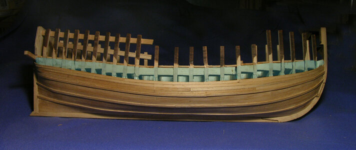
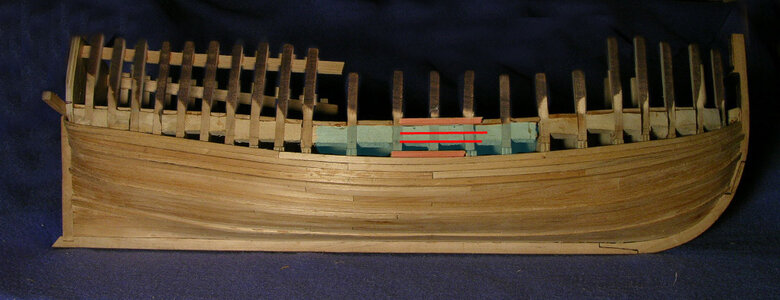
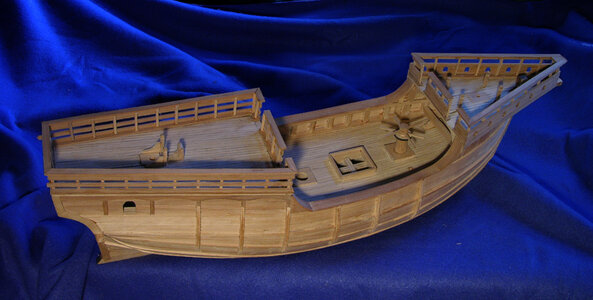
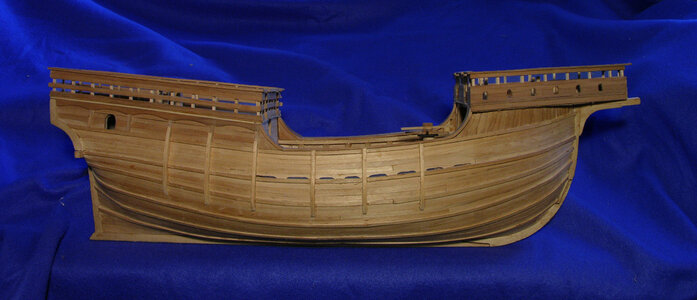
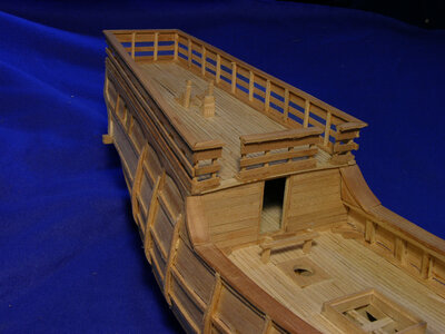
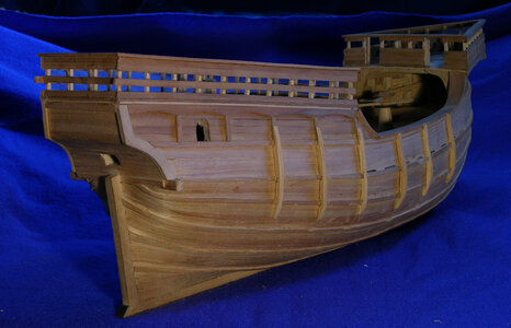
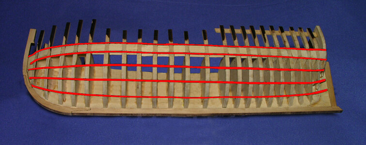
If you were in a shipyard and the foreman yells to you get a crew and line off the hull the photos show what you would be doing. Using 1/8 wide electrical tape the hull is divided into belts or sections for planking. By lining off the hull it insures a smooth run of the planking. Start by measuring the hull in midship into the number of planks it will take to cover the hull. It takes seven planks from the sheer to the cap rail then a belt of three
planks and three belts of four planks and finally the bottom planks. First line off the sheer and the bottom plank belts. Next start the center belts at midship and allow them to run as natural as possible, the tape strips will want to run up the sternpost and stem so at the ends divide the remaining space evenly between the three center belts.
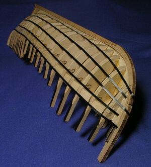
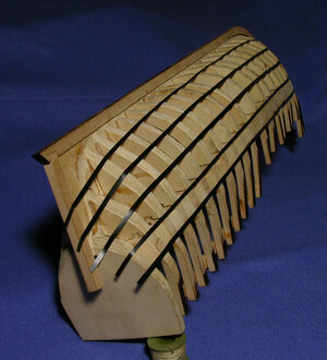
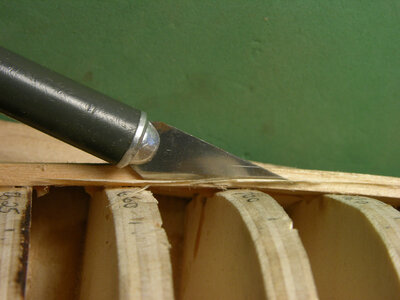
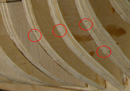
When the hull is lined off take a knife and notch along the tape to mark their locations.
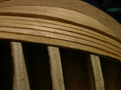
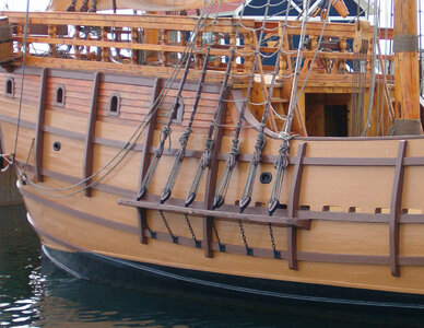
Each strip of tape on the model represents a wale on the hull.
Last edited:


