• LUCZORAMA SHIPWRECK SCAVENGER HUNT GIVEAWAY. 4 Weeks of Fun • 1 Legendary Prize ((OcCre’s Fram Ship)) • Global Crew Welcome!
    **VIEW THREAD HERE**

Greco-Ottomon Ship Plans

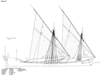
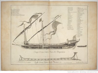
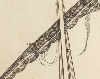
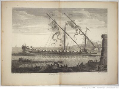
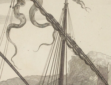
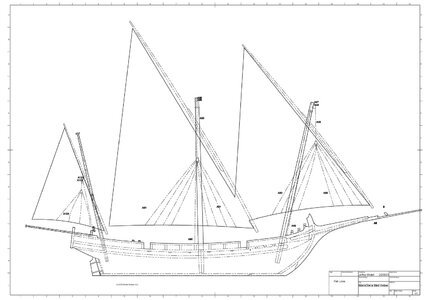
Here is the galley-type single-side (based on other materials I have looked at) footer rope leach-line system. It, too, differs from what I see in the Antoine Roux painting. There is no horizontal yard so these lines must be attached to the sail. Not sure if the text is Russian or Greek -- can anyone tell me what line 14 is called in English?

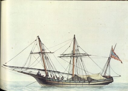
In reconstructing the Greco-Ottomon ship, I am trying to match the painting to the extent I am not convinced it is wrong.

DRGalera04.jpg
 
Last edited:
Hi. Too many queries…I had to sharpen my faiding English. :)

Firstly, I didn’t say that, what was being used for Gr traditional vessels was the same system but a “similar” one…But if on the painting ignore the one part of the system, what is left - shown is the same one with what I suggest.

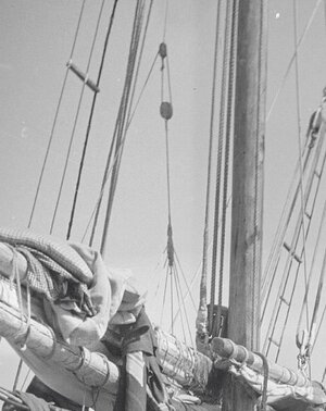
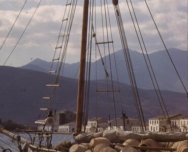
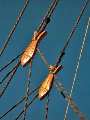
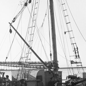
In this, let’s say Gr system, the lines under the “fish” are permanently attached on the boom on a gaff rigged vessel and the line above the fish is attached on the mast by a hauling system. See the photos, the clearest I could find from my collection.

Usually that system had-has one part of "guidelines", because the sail was being lowered inside the vessel and the crew could handle and fasten the folded sail from one side of the boom wile the sail was kept from the other side by the "guidelines".

I must say that in a gaff rigged large vessel definitely must be two of those systems (two "fishes"), because as you can imagine it’s impossible to be one “fish” over the peak having "guidelines" down to the boom.

Those two “fishes” in the blue colored photo, apart from their use, are also a decorative note in a recent small vessel and without the need of the second one. It was not always a wooden carved fish but just a wooden oval shaped part, with holes letting the lines adjust back and forth, as you said

In the painting we see one “fish” with two sets of "guidelines", and I think it wouldn’t impact the sail because it’s attached by the end of the sail, in a small triangular area and being loose. See the length of the "guidelines", which I think they would be a bit longer from the distance of the sail area where they worked in order not to effect the sail when the yard was in position-up.

As I see it would be only a small triangular area of the sail, freely fold and unfold between the space that is given by the “fish” and the length of the "guidelines".


As about any bibliography, there is only a reliable book with the title: “The Greek Traditional shipbuilding” which is referring on the Gr traditional vessels of around 1900 and it gives only hull plans and is written in Gr language.


You can see its first digitalized form of it and in English language, in two parts in below link: https://research-repository.st-andrews.ac.uk/handle/10023/7116?show=full


The explanation of the drawing is in Russian language and I’m sorry but I don’t think there is any plan- you could find, of Greek polacre.

Thx
Bouma-41.jpg Varkalas-85.jpg HEE.jpg CRW.jpg
 
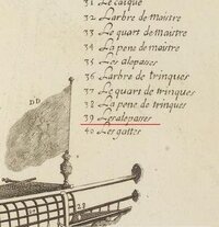
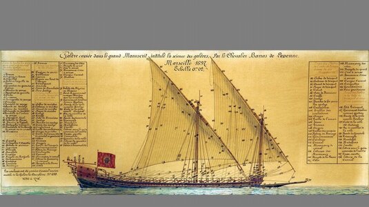
I think I have a headache. Actually, that Galeas drawing you provided is pretty much what I decided upon, except one-sided. Any chance you can read what number 39 is? Or type it out so I can check out google translate.
 
Last edited:
Ok. I've made a search...
The no 39 reffers to the wooden parts of the yard-antena "Les alepasses" which by the tranclation of the Wiktionary says:
feminine alepasse _
( Navy ) ( Aged) piece of oak that unites and reinforces antenna - type yards .
eeeee.jpg
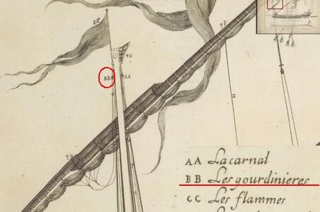
Instead the explanation BB is much interesting
dddddd.jpg
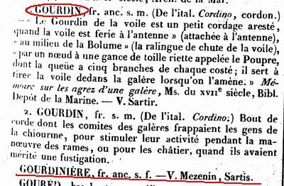
In the Glossaire nautique I found the terms as in photo
ooooooo.jpg
The "gourdiniere" refers to "Mezenin", something that has to do with a tent over the deck, under the crew was protected but the "Gourdin" has the below translated explanation...
1. GOURDIN, fr. old. s. Mr. (From the Ital. Cording, cord.) The Cudgel of the sail is a small cordage edged, when the sail is ferie à l'antenne" (attached to the antenna), "in the middle of the bolume" (the luffline fall of the sail), “by a knot in a gance of toille riette called the Poupre, the tail of which has five branches on each side; it is used to pull the sail into the galley when it is lowered. »> Memoir on the pleasures of a galley, Ms. of the xvi1 century, Bibl. Navy depot. -- V. Sartir.

Food for thought....but I think it describes what I suggested.

In addition, maybe a French speaking member, could read the explanation in the below photo especially no 125-130.
Thx
333.jpg
 
Last edited:
Can you point me to research materials on appropriate cannon? Port is 2' wide. I have plenty of materials on British, Spanish and French cannon but found next to nothing on Greek or Ottomon 18th century cannon.

It probably doesn't matter much as I guess a merchant would have used "low-bidder" (my fear anytime I am on an airplane looking at the wing).

Thanks Again!

NEW 1XEBEC_02.jpg
 
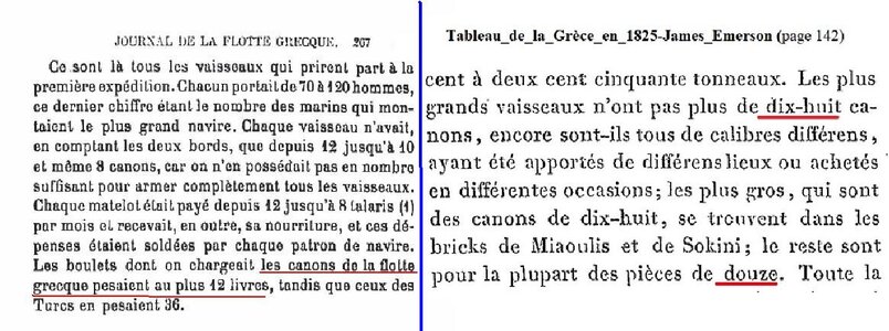
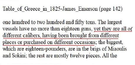
According to many historians (Westerns and Greeks) the greek merchant fleet before the war of independence (1821) , was carrying only small calibre cannons mostly 12lib and up to 18 lib by following the French unit of measurement of weight of the ball.
These small calibre cannons were the only allowed by the Ottomans under of whose occupation the Greeks were trading and as a protection from the pirates.
Later and as the war started the ships were being armed with largers callibers from the enemy spoils.
The painting, I think showing rather a merchant vessel carrying maybe four (4) cannons (as the number of gun ports at the port side) and thus I would suggest cannons of 12lib.
Thx
calibre.jpg
 
That info is very useful. No sense in a merchant having just popguns unless by law.

Agreed, need 4 cannons of relatively small caliber. Additional Info:

1) painting done in 1796
2) ports are 2' wide.
3) I note the cannon are let out but the ship is at rest. It would be dangerous to sail with the cannon out all the time (dragging in the water). Plus, the ship does not appear to be in combat. I do not understand them being run out in the painting. Maybe artistic license? Making more room to move cargo?

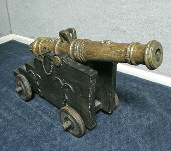
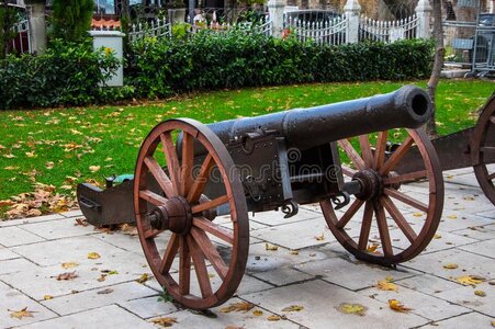
I am really hoping your library includes drawings of actual Greek or Ottomon cannon, 18th century, -- that is what I really need (failing that I do intend to use continental-style cannon). We can size them by eye to match the painting and never worry about the true caliber (assuming we do not get formula showing placement of every decorative or reinforcement element).

I found only an Ottomon bronze cannon, which does not look like those of the painting -- and other photos of unknown time period, caliber, etc.

Thanks Again, Jeff

e7f40b12923c9ae6960154c2f7eaf19a--ottoman-empire-cannon.jpg

OIP (1).jpg

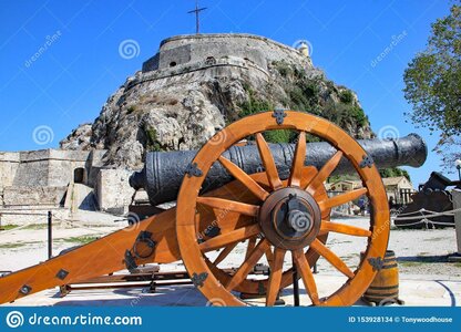
cannon-front-old-fortress-corfu-town-greece-153928134.jpg

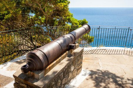
ancient-cannon-paleokastritsa-corfu-kerkyra-greece-30891329.jpg

R.jpg

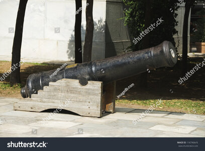
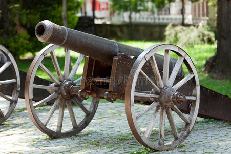
bursa-cannons-hill-near-clock-tower-45597251.jpg

old-ottoman-cannon-exibited-overlook-city-bursa-105640029.jpg
 
Last edited:
The previous French text (translated) also mention the sources (nationality) of the Gr naval guns which are undetermined...:cool:
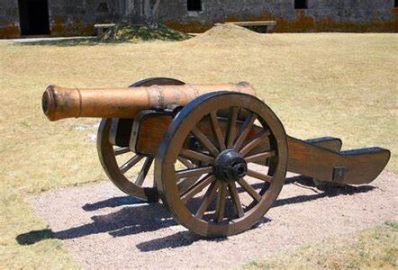
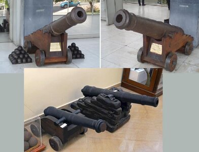
So what I could find is the below photos, which are from two war museums (Athens-Thessaloniki) that show naval guns of that era.
Unfortunately the label don't mention the caliber but because of the size and the diameter of the barell, it might give an idea of 12pdr cannons.
Thx
calibre-1.jpg
Naval_gun_1.jpg
 
Last edited:
The previous French text (translated) also mention the sources (nationality) of the Gr naval guns which are undetermined...:cool:
So what I could find is the below photos, which are from two war museums (Athens-Thessaloniki) that show naval guns of that era.
Unfortunately the label don't mention the caliber but because of the size and the diameter of the barell, it might give an idea of 12pdr cannons.
Thx
View attachment 355071
View attachment 355072
Thanks!
 
Well, If I get it well, in your drawing is not showing what is in the painting. In the painting there are two sets spraded lines, one in every side and that system it's not for reefing the sail, but to bring the sail close to the yard when it is being lowering from the mast.
Are these spreaded lines on both sides of the sail, or just in the right one.? Unless if you're showing only the starboard but then the "fish" should been over the yard.

I don't think that this kind of rigging is a Gr patent...
See there https://en.wikipedia.org/wiki/Lazy_jack
and also for what in Greece is called "fish" the wiktionary says :
euphroe (plural euphroes) (nautical) A long wooden slat, with holes for cords...

I'm searching for a relative term in Greek but until now I find only the word "μπρουλια" (broulia) that comes from "Brails" but I don;t think that is the proper one.
Thx
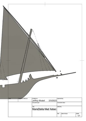
 
If you want each line to go on both sides of the sail, that means the two bunches on the painting are each one side of the sail so there are a total of 4 lines each of which does an ellipse around the sail, which is what I originally drew but did not understand at all (though I did use a dead-eye instead of an oval shaped block). Here it is again (only with an oval shaped block). And I could call it "Furling Guide" instead of "spill line". I put a fish tail on the blocks in the prior diagram because of your photo and the blurriness of the painting allowed for it. However, if fish are always a pair then I cannot use them. There is only one block controlling all the lines on the fore course in the painting.

There is no boom on this sail so whatever the lines are, fastened to something or not, they are not attached to a boom.

Below is what I think you are suggesting. If not, please feel free to do a hand drawing. I just want to be as accurate as possible on these plans.

rev furling lines.jpg
 
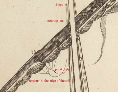
A new search gave me more details about the term “gourdinière”.

cordage.jpg cordons.jpg

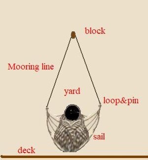
So, according to this new description and the sketch, I think that above the yard there is one block (not a "fish") from which passes a line to each side of the sail having a pin permanently attached at each end.
There are two sets of fan-spread cords attached- sewed at the edge of the sail facing opposite each other or with some distance.
The fan-spread cords in each side are tide together and a loop is forming at their connection point.
The pins on the edges of the two branches coming from the block, by passing trough the each side loops, are connecting and completing the system.
When the yard is lowered, the below sketch with a front view, gives the whole idea.
Thanks

final.jpg
 
Last edited:
The form you have suggested differs from the painting and, so, is not a viable solution. Anything that differs from the painting, unless it is 100% certain the painting is wrong, must be rejected to maximize the odds of historical accuracy. If you look at the painting there is a single block to which two sets of 8 legs attach (8, not 10, that's important) are attached. The painting does not show a line running from the block down to a new split point, as you have drawn. Nor does the painting show any release toggles anywhere on this rig. Can you think of a viable piece of rigging that does not contradict the painting (or pick one of my ideas that you prefer)?

Also, you seem to know a very lot about Greek ships. Why do France and Britain have great repositories of ship plans, but even though I have contacted at least six Greek museums I have yet to find a single polacre or xebec plan? Did the island shipwrights burn their plans, or what?
 
Back
Top