• LUCZORAMA SHIPWRECK SCAVENGER HUNT GIVEAWAY. 4 Weeks of Fun • 1 Legendary Prize ((OcCre’s Fram Ship)) • Global Crew Welcome!
    **VIEW THREAD HERE**

Proxxon Mill Best Practices Question

Joined
Aug 23, 2020
Messages
8,219
Points
838

Location
Wadsworth, Illinois, USA
Hello Forum Members,

I have the small Proxxon Mill (mf70) and as I fabricate parts for my ship model, I think to myself "I should/could make this on my mill." But I don't. The problem I face is alignment in the x-y axis. I have added a gauge to control the z axis (vertical axis) but what is the best way to get pieces straight on the milling table?

For example, if I want to cut a 1mm slot in the center of a 3mm x 3mm square stick (along its 10 cm length) how do I get the 3x3 piece perfectly positioned on the milling table so that the slot stays in the center of the stick over the 10 cm distance? Yes, I could do this on a mini table saw... But my question is how to do this on a mill. Surely there is a way to accurately position stock on the milling table???

My thanks.
 
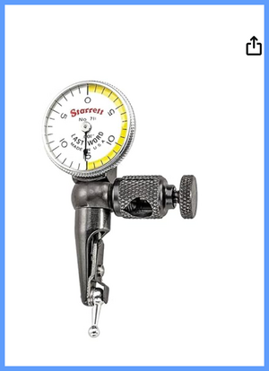
Paul, What I use is my Starrett Last Word Indicator. Mount on the spindle and traverse the x-y axis
A little pricey for some but well worth it. It's smaller than most dial indicators


Depending on the vertical clearance on your mill there may not be sufficient clearance and it may require a different mount location other than the spindle. Works great on my mini mill. If you can mount it on the spindle you will have to 'lock' the spindle so it doesn't rotate.
Lastword indicator.png
 
Last edited:
Greetings, mon ami!

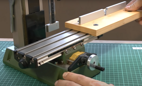
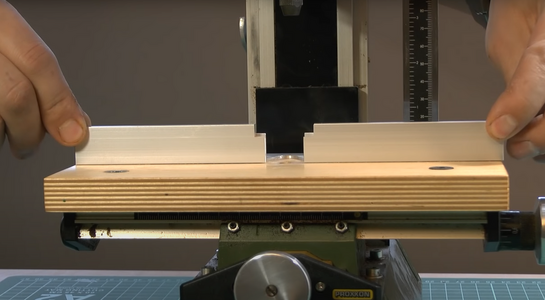
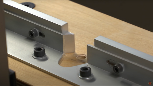
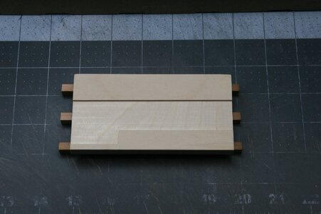
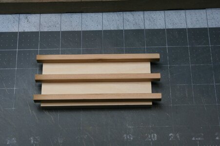
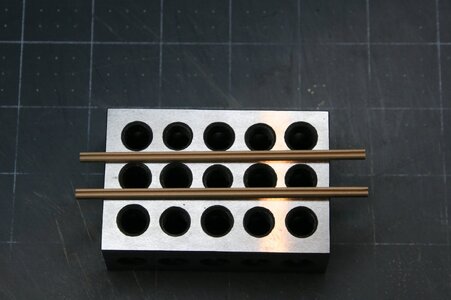
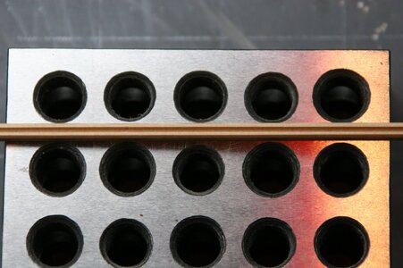
One of the ways, not the immediate one, is to make the jig similar or identical to this (images below)

1722779899813.png
1722779925762.png
1722779938250.png
Here is the video, mostly about the miller itself, but start watching from 11.35 position, Sergey Kutuzov (his name), describes the make of this jig. It is in the Russian language, but self-explanatory. If you need details, I will help you translate,


For immediate resolution, you can mount the straight plank along the 'Y' axis, put the 3mm plank against the mounted plank, find the center of the 3mm part, set the required deep using the 'Z' axis, and.... use your mill as the router. ;)
 
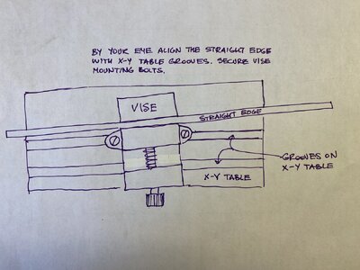
Using the dial indicator as rtibbs descried above is the best true way to achieve parallelism between your working piece and the X-Y moving table. But for a quick adjustment I often set it by gripping the long straight edge (as a steel ruler) into a vise mounted on X-Y table and adjusting the vise position such a way they the straight edge is parallel to the grooves on the X-Y table. Locating the cutter in the center of 3 mm wide plank for cutting a slot along the plank I do by eye too, but often with limited success. I mark the center on the working piece with a pencil first.
 
Last edited:
Paul, What I use is my Starrett Last Word Indicator. Mount on the spindle and traverse the x-y axis
A little pricey for some but well worth it. It's smaller than most dial indicators


Depending on the vertical clearance on your mill there may not be sufficient clearance and it may require a different mount location other than the spindle. Works great on my mini mill. If you can mount it on the spindle you will have to 'lock' the spindle so it doesn't rotate.
View attachment 462835
Thanks, Ron. But isn't that used to level the table??? Or maybe I can't imagine how I would use that gizmo to solve my problem.
 
Greetings, mon ami!

One of the ways, not the immediate one, is to make the jig similar or identical to this (images below)

View attachment 462836
View attachment 462837
View attachment 462838
Here is the video, mostly about the miller itself, but start watching from 11.35 position, Sergey Kutuzov (his name), describes the make of this jig. It is in the Russian language, but self-explanatory. If you need details, I will help you translate,


For immediate resolution, you can mount the straight plank along the 'Y' axis, put the 3mm plank against the mounted plank, find the center of the 3mm part, set the required deep using the 'Z' axis, and.... use your mill as the router. ;)
Thanks, Jim. That might do the trick. I'll take a closer look. I can imagine the fence being in the way as shown but I don't need to use a fence that is that tall...
 
Using the dial indicator as rtibbs descried above is the best true way to achieve parallelism between your working piece and the X-Y moving table. But for a quick adjustment I often set it by gripping the long straight edge (as a steel ruler) into a vise mounted on X-Y table and adjusting the vise position such a way they the straight edge is parallel to the grooves on the X-Y table. Locating the cutter in the center of 3 mm wide plank for cutting a slot along the plank I do by eye too, but often with limited success. I mark the center on the working piece with a pencil first.
Thanks Yuri. Could you take a photo of how you are using a vice? I can't quite imagine this in my head.
 
Thanks, Ron. But isn't that used to level the table??? Or maybe I can't imagine how I would use that gizmo to solve my problem.
Unless I misunderstood your question I thought you were wanting to cut a long slot along the piece. If so then you would have the indicator fixed and indicate along the piece as you moved the table and adjusting the piece until the indicator showed no runout.
Maybe I confused you by saying attach the indicator to the spindle. ( I did say you would have to lock the spindle from rotating)
Tramming the table is something you would do with the indicator mounted to the spindle then rotate it 360 degrees to see the head was aligned to the table.
I've also made a fixture similar to Jim's which would be tee shaped and fit snuggly into to table slot then I would take a light cut along its length assuring a straight cut on anything attached to it. Definitely something to consider if cutting multiple pieces without having to indicate each piece.

Ron
 
I've also made a fixture similar to Jim's which would be tee shaped and fit snuggly into to table slot then I would take a light cut along its length assuring a straight cut on anything attached to it. Definitely something to consider if cutting multiple pieces without having to indicate each piece.
This is what I think I need. Any chance you could post an image? My difficulty lies in positioning the workpiece in perfect alignment with the adjustable table...so that when I crank the wheel(s) it cuts where I think it should be cutting...

I hate being the dumbest kid in class...:(. I can dissect the brachial plexus but I can't cut a piece of wood...:rolleyes:
 
I hate being the dumbest kid in class...:(. I can dissect the brachial plexus but I can't cut a piece of wood...:rolleyes:
Hardly the dumbest kid in the class Paul. I have no idea what you just wrote. :(
We're in the midst of Hurricane Debby rain bands right now but I'll venture out to the shop shortly and see if I can find my fixture. Unfortunately when I finish with a certain project I don't always keep my custom fixture. :oops:
You must not be too far from me. Debby just dropped a bunch of rain here and a little bit of wind. :)
I'll keep my fingers crossed for you.
 
I hate being the dumbest kid in class...:(. I can dissect the brachial plexus but I can't cut a piece of wood...:rolleyes:

I’m with you sitting in class Paul. I can take you across the Pacific with a sextant, chronometer and tables but I’ve been struggling with the same positioning and alignment issues you describe for a while now :).
 
Hello Forum Members,

I have the small Proxxon Mill (mf70) and as I fabricate parts for my ship model, I think to myself "I should/could make this on my mill." But I don't. The problem I face is alignment in the x-y axis. I have added a gauge to control the z axis (vertical axis) but what is the best way to get pieces straight on the milling table?

For example, if I want to cut a 1mm slot in the center of a 3mm x 3mm square stick (along its 10 cm length) how do I get the 3x3 piece perfectly positioned on the milling table so that the slot stays in the center of the stick over the 10 cm distance? Yes, I could do this on a mini table saw... But my question is how to do this on a mill. Surely there is a way to accurately position stock on the milling table???

My thanks.
One way I’ve achieved what you are describing is a bit rube-Goldberg but works for me.
I line up and bolt down the mini vise on the x-y table using a machinist square. I then sneak up on the edge of the workpiece by turning the x or y wheel as appropriate. I use a piece of paper that I know 0.10mm thick (20# bond paper) when I feel resistance on the paper “shim” I stop. I know I’m 0.10mm from my workpiece. If the work is 3mm and I want a 1.0mm groove down the middle the math says I need to adjust the table by 1.1mm and “Bob’s your uncle” your groove is centered. Like I said kind of crude but it works…
Thanks for your nice description that was really helpful, but I've got some trouble with it! Cause I don't have any uncle and so what should I do with Bob?! Is that ok if I pretend that Bob's my friend or something?!
 
Thanks to everyone who has been contributing to (or just reading) this thread. I thought I would give you an update on some of my current solutions...

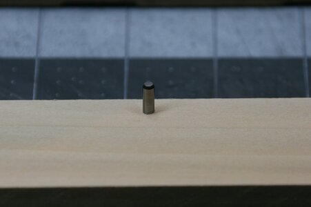
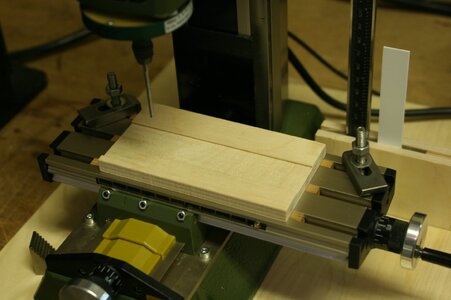
First, I took the shaft of a broken mill and set it into a flat piece of wood. I'm sure you've seen this solution before but just in case you haven't ... what you do is set up the post relative to the milling head and slide the workpiece along the post. These keeps the 'cut' in the same place along the workpiece. I used something similar to cut a rabbet and it worked fine - but if the workpiece is long it's hard to keep it up against the post over the full length of the cut (but not impossible):

IMG_0973.JPG

But what I wanted to show you is this...

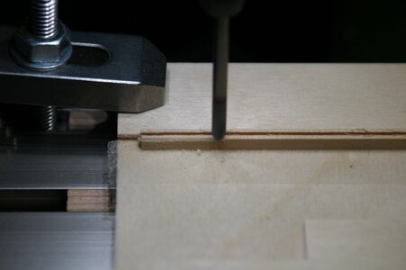
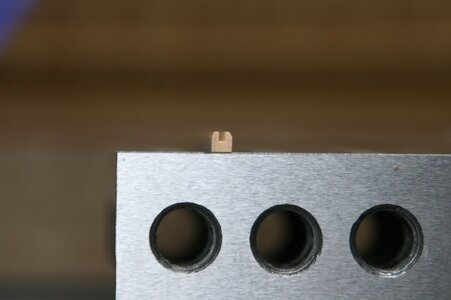
I made a 'sled-looking' thing with guides that sit (perfectly) into the slots on the XY table. I then milled down about 2/3rds of the surface 2 mm or so. Now, whenever I return the jig to the XY table, the left to right 'fence' is always perfectly aligned.

IMG_0970.JPG

IMG_0971.JPG

IMG_0975.JPG

Proof of concept:

IMG_0977.JPG

IMG_0978.JPG

IMG_0979.JPG

IMG_0981.JPG

Next, I'll add the suggested edge finder. And I'll also continue to explore other solutions for other applications.
 
Awesome thread. I have my mill setup as a CNC machine, but that doesn't mean my cuts are more accurate. I don't know what I am doing with this mill, and quite frankly I am scared to use it. I even purchased an extra XY table in case I make a mistake. Thank you for the sharing of information.

The CNC approach allows for auto homing so that 0,0 is always at the same place, but I am not there yet because I don't have limit switches installed on the mill. That is where I am at. But the mini vice must be oriented properly so that it's sides are in alignment with the X and Y axes. For the z axis, I use a sheet of paper to adjust the 0.

As they say before you automate a process you must be able to run the process manually first so I am building this process incrementally. Once again thank you for sharing your information.
:):)


Back
Top