I am working on this kit but I am a bit confused about the second planking. The instructions say do the second planking and shows pictures of the finished hull. It looks like the second planking completely covers the first planking. My confusion is: do the copper plates go on top of this second layer or is this area cut back to the first planking to have the plates flush with the second planking.
-

Win a Free Custom Engraved Brass Coin!!!
As a way to introduce our brass coins to the community, we will raffle off a free coin during the month of August. Follow link ABOVE for instructions for entering.
-

PRE-ORDER SHIPS IN SCALE TODAY!
The beloved Ships in Scale Magazine is back and charting a new course for 2026!
Discover new skills, new techniques, and new inspirations in every issue.
NOTE THAT OUR FIRST ISSUE WILL BE JAN/FEB 2026
You are using an out of date browser. It may not display this or other websites correctly.
You should upgrade or use an alternative browser.
You should upgrade or use an alternative browser.
Panart Victory bow section
- Thread starter roadrunner
- Start date
- Watchers 5
- Joined
- Apr 15, 2025
- Messages
- 151
- Points
- 103

Were you able to move forward? If so what did you decide on? If not some pictures might help explain the problem. Like the instructions and current progress.
Thanks for asking. I had a look at some finished bow sections and the copper plates have been put on the second planking and a wooden strip has been glued along the join between the second planking and the copper plates. This way the difference in thickness between the copper plates and the second planking doesnt look obviousWere you able to move forward? If so what did you decide on? If not some pictures might help explain the problem. Like the instructions and current progress.
Hello, I have another problem you may be able to help me with. I put the template of the gunports against the hull and traced the outline of them with a pencil. When I checked the positions of them I noticed that some of them were in line with the frames. Have you any suggestions about what I should do. Thanks
- Joined
- Apr 15, 2025
- Messages
- 151
- Points
- 103

Hum I think I have seen some posts about this on the forum but I am not sure where.
Maybe @Corsair @Namabiiru @Peter Gutterman @DARIVS ARCHITECTVS or @Jimsky can help as they have helped me a lot :3
Maybe @Corsair @Namabiiru @Peter Gutterman @DARIVS ARCHITECTVS or @Jimsky can help as they have helped me a lot :3
Does the gunport just barely catch the edge of a frame? or does the frame go right through the middle of where the gunport would be?
I would think the first step would be to see what is out of place on your build. Do you have the frame in the wrong place, or do you have the gunport template in the wrong place? or is the gunport supposed to be where the frame is?
I would think the first step would be to see what is out of place on your build. Do you have the frame in the wrong place, or do you have the gunport template in the wrong place? or is the gunport supposed to be where the frame is?
Please check the instructions again as to where the frames and gunports should be, since they should not conflict with each other if the kit manufacturer made the kit design correctly. I think something may be off position on your model, or you are plotting the gun ports in the wrong locations. I have dealt with gun ports being too close to frames before, but that was because I MOVED the gunports and changed the design of the model myself, and had to cut away the frame bulkheads to make room for gun carriages and rigged gun tackles. A kit manufacturer makes mistakes on occasion, but usually not ones that offer great conflict with parts interference. Since your model is a cutaway of a hull, a conflict between gun ports and frames is serious because it will be PLAINLY VISIBLE. So, my solutions to the problem will not work for your model. Check your parts locations and take measures and compare them to the model plans.Hello, I have another problem you may be able to help me with. I put the template of the gunports against the hull and traced the outline of them with a pencil. When I checked the positions of them I noticed that some of them were in line with the frames. Have you any suggestions about what I should do. Thanks
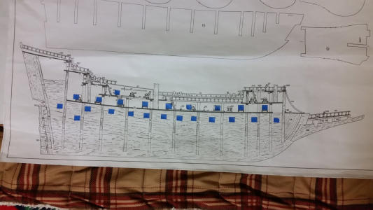
My model showing hull bulkheads relative to gun ports. Look how close the gun carriages are in sereval locations. Note that on my model the locations of the bulkheads are NOT the same as they would be on the real ship. Originally I assumed that the kit manufacturer made them so, but learned later than they were not. Guns on the lower gun deck were supposed to be fake cannon barrels sticking into pieces of wood, not complete cannon carriages, so when I desired to install complete carriages, Aither the wheels on one side of a carriage had to be made thinner or a section of the bulkhead had to be cut away to allow more space, before the first layer of planking was laid down.
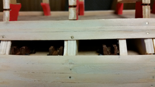
Carriages sat right up against bulkheads on this model, which would not be the case on a real ship. Frames would not be this close to guns, or the gun crews would not be able to operate the guns. This model was clearly designed to be viewed from the outside only, and the interior is totally hidden. Your cutaway model must reflect the actual location of frames and gunports.
Check your work against Jeff-E's on the Model Ship World forum. His build log is very detailed. It can help you find where things may be going off track on your model.
Jeff-E
Posted October 24, 2013Hi All,
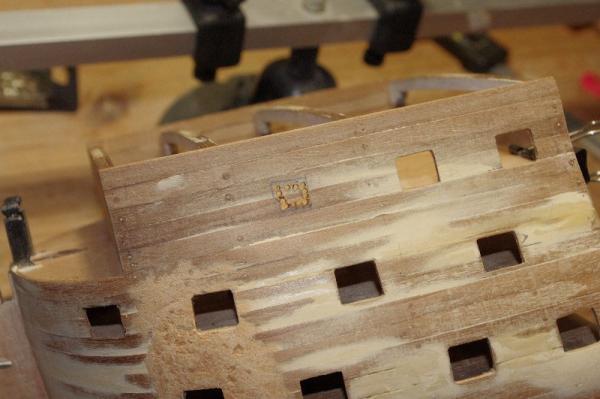
After they were maked out and I was happy with the positon of them the gunports were cut out. This was done as per the instructions by drilling a series of small holes inside the marked lines and then carefully cutting out that section and finally finishing it to size with a file.
Last edited:
Late responding to your original question, but since there haven't been any better suggestions, my recommendation would be to complete your second planking over the entire hull before coppering. If you only do second planking down to the waterline then continue with copper, then the the copper will be flush with or slightly below the surface of the planking. That wouldn’t look right to me since coppering went on top of the planking on the real thing.I am working on this kit but I am a bit confused about the second planking. The instructions say do the second planking and shows pictures of the finished hull. It looks like the second planking completely covers the first planking. My confusion is: do the copper plates go on top of this second layer or is this area cut back to the first planking to have the plates flush with the second planking.
Last edited:
Are you using plans or a template? The plans are an orthogonal projection of the 3D hull onto a flat surface, so the alignment will be off near the stern and particularly the bow where the hull curves away from imaginary surface the plans represent. A template designed to conform to the shape of the hull should already have accounted for that.Hello, I have another problem you may be able to help me with. I put the template of the gunports against the hull and traced the outline of them with a pencil. When I checked the positions of them I noticed that some of them were in line with the frames. Have you any suggestions about what I should do. Thanks
Not speaking from my own direct experience, but have seen on other logs that it is not unusual to cheat gunports slightly forward or aft specifically to avoid frames. On thing to watch out for if you do that is to check the placement of the chainplates so that you don’t position a gunport where those would go.
A little cheating was done on the actual framed ships as some frames were jogged to allow the gun ports to line up with a frame on each side. Not quite the same as moving the ports instead of the frames, but the spaces were not always the same between ports on a given deck and ship.Not speaking from my own direct experience, but have seen on other logs that it is not unusual to cheat gunports slightly forward or aft specifically to avoid frames.
Allan
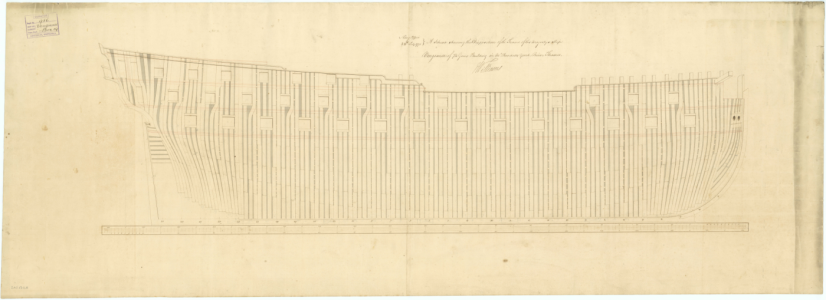
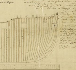
An extreme example of Vengeance 1774
Minor frame shape adjustment at second gun port
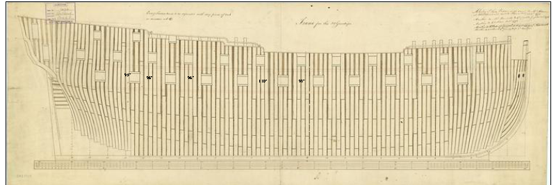
Spacing at the QD break was usually more than the other spaces between ports due to (I think) the need for room for the steps. In this case the spacing was 95 inches or 96 inches between most ports, but one is 110" and the adjacent space is 93"
Thanks for the detailed reply. The frames are in the correct place and two of the top row of gunports on each side would have been exactly in the middle of them. I have moved them over a bit and they now clear the frames. I have moved them along half the width of the gunport so it wont be noticed. Perhaps the template is wrong.Does the gunport just barely catch the edge of a frame? or does the frame go right through the middle of where the gunport would be?
I would think the first step would be to see what is out of place on your build. Do you have the frame in the wrong place, or do you have the gunport template in the wrong place? or is the gunport supposed to be where the frame is?
Thanks for the reply. Two gunports on the top row would have been in the middle of the frames so I have moved the holes slightly.. It wont be noticedPlease check the instructions again as to where the frames and gunports should be, since they should not conflict with each other if the kit manufacturer made the kit design correctly. I think something may be off position on your model, or you are plotting the gun ports in the wrong locations. I have dealt with gun ports being too close to frames before, but that was because I MOVED the gunports and changed the design of the model myself, and had to cut away the frame bulkheads to make room for gun carriages and rigged gun tackles. A kit manufacturer makes mistakes on occasion, but usually not ones that offer great conflict with parts interference. Since your model is a cutaway of a hull, a conflict between gun ports and frames is serious because it will be PLAINLY VISIBLE. So, my solutions to the problem will not work for your model. Check your parts locations and take measures and compare them to the model plans.
My model showing hull bulkheads relative to gun ports. Look how close the gun carriages are in sereval locations. Note that on my model the locations of the bulkheads are NOT the same as they would be on the real ship. Originally I assumed that the kit manufacturer made them so, but learned later than they were not. Guns on the lower gun deck were supposed to be fake cannon barrels sticking into pieces of wood, not complete cannon carriages, so when I desired to install complete carriages, Aither the wheels on one side of a carriage had to be made thinner or a section of the bulkhead had to be cut away to allow more space, before the first layer of planking was laid down.
View attachment 521873
Carriages sat right up against bulkheads on this model, which would not be the case on a real ship. Frames would not be this close to guns, or the gun crews would not be able to operate the guns. This model was clearly designed to be viewed from the outside only, and the interior is totally hidden. Your cutaway model must reflect the actual location of frames and gunports.
View attachment 521874
Check your work against Jeff-E's on the Model Ship World forum. His build log is very detailed. It can help you find where things may be going off track on your model.
Jeff-E
Posted October 24, 2013
Hi All,
After they were maked out and I was happy with the positon of them the gunports were cut out. This was done as per the instructions by drilling a series of small holes inside the marked lines and then carefully cutting out that section and finally finishing it to size with a file.

Strange. The other build logs did not mention an alignment problem.Thanks for the reply. Two gunports on the top row would have been in the middle of the frames so I have moved the holes slightly.. It wont be noticed
I dont understand what is wrong. The frames are def in the right place as the decks for the different levels have cut outs to fit the frames. I cant imagine the template being wrong. I am going to compare the Jefe-e picture with my model and try find out what I may have done wronng. Its beginning to puzzle me.
Stupid question: Is the template being laid on the hull backwards?I dont understand what is wrong. The frames are def in the right place as the decks for the different levels have cut outs to fit the frames. I cant imagine the template being wrong. I am going to compare the Jefe-e picture with my model and try find out what I may have done wronng. Its beginning to puzzle me.
 Done that one once!
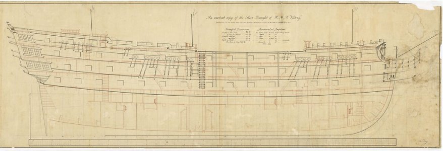
 Do you have a copy of Longridge's Anatomy of Nelson's Ships? The first drawing below is from the book. There is a scale under the drawings. Compare the location of the gun ports to those on your kit drawings to see if they match up. Note the different sizes of the gun ports for each deck as well. Do these vary on your drawings like those below?
Allan
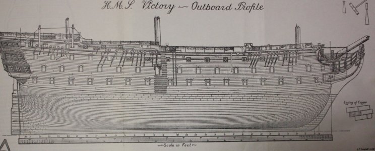
From RMG - bear in mind the RMG drawing is from 1765 so may be different than the 1803 re-build configuration.
Allan

From RMG - bear in mind the RMG drawing is from 1765 so may be different than the 1803 re-build configuration.

Last edited:
I have found the problem. The template is cut out incorrectly. I had a look at the earlier pic of Jeff-E bow and it clearly shows a long spaceStupid question: Is the template being laid on the hull backwards?Done that one once!

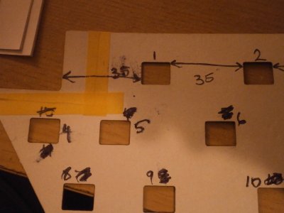
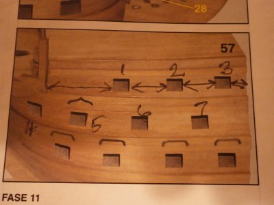 from the l/h edge to the start of the first top gunport and equal spacing to ports 2 and 3. Then a smaller distance to the edge of the planking. The picture of the template shows the distance from the l/h edge of the bow to the start of gunport 1 is 35mm. Its the same 35mm from gunport 1 to gunport 2 and also to gunport 3 Then its 11mm to the r/h edge of the bow. You can see that the template shows gunport 1 l/h side is almost in line with the r/h edge of gunport 5 but the photo from the instruction book shows the r/h edge of gunport 1 almost in line with gunport 6 l/h. I cant think how they have cut out the template incorrectly. The masking tape is there because I cut out this part to try and make it fit correctly but its back in the exact position before I cut it The pictures are the template and a photo from the instruction book
Glad you found the cause. 
Note also in the bottom picture that the tops and bottoms of the gunports follow the shear line of the deck so that many gun ports are not rectangular, as they all are on the template.
Glad you found the cause!


