• LUCZORAMA SHIPWRECK SCAVENGER HUNT GIVEAWAY. 4 Weeks of Fun • 1 Legendary Prize ((OcCre’s Fram Ship)) • Global Crew Welcome!
    **VIEW THREAD HERE**

Desktop Lathe recommendations and method suggestions for shaping ship masts

Joined
Jul 14, 2024
Messages
15
Points
48

Hi
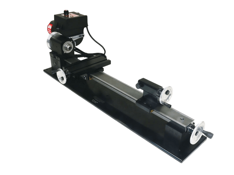
I'm UK-based, I have a 5' long work desk, and I'm looking to get a desktop lathe for shaping ship masts and other detailed work. I currently use the dowel in a cordless drill and shape with sand sandpaper method, which is a good method, but not 100% accurate. I have a good eye for detail, but I want a more precise way of working with the dowel, I have looked online and found that most desktop lathes that are a manageable weight and size, only have a max length of 150mm give or take between the centers if thats the correct terminology, which is suitable for making spars, topmast, topgallant and royal mast depending on the scale of the model.

When it comes to the lower mast, a bigger lenght is needed, can anyone recomend a manageable sized and a reasonably priced lathe as the bigger they are the more expensive. Also I expect there are many other methods that can be used to get the same result that I am not aware of so any suggestions would be welcome.

Here are the masts that I made for my Occre Revenge, they turned out pretty well.


Thanks

2024-02-04 12.32.06.jpg
 
I like those dowel makers suggested by Jim!
I personally wouldn't want to buy a lathe just for stuff like this. Decent lathes just cost too much for such limited uses. For 'me', I'm eyeballing Proxxon's PD 250/E. It seems to be a solid piece of equipment and would be great for wood 'AND' metal alike. The price is kinda up there, but I do a lot of metal work too, so this lathe would be a logical choice for a person like me.
 
What comes to my mind is the dowel maker. It is a pretty simple tool, you can buy relatively cheap or make yourself a suitable diameter and length that you might need.

View attachment 530273

View attachment 530274


Thanks, I've seen the black and red dowel maker but do you know the make of the top image ( what's in the box) ?, Using a dowel maker in combination with tapering methods would get a nice result. The videos you posted look interesting as well, my carpentry skills aren't the best, but I will have a go at making a jig myself.
 
I like those dowel makers suggested by Jim!
I personally wouldn't want to buy a lathe just for stuff like this. Decent lathes just cost too much for such limited uses. For 'me', I'm eyeballing Proxxon's PD 250/E. It seems to be a solid piece of equipment and would be great for wood 'AND' metal alike. The price is kinda up there, but I do a lot of metal work too, so this lathe would be a logical choice for a person like me.
Yeah, I agree, if I had money to spare, I would invest in a good lathe, but sadly, I don't lol, plus I have limited work space, I live in a small apartment and utilised the space as best I can. I know I can get the red and black dowel maker on Amazon, but I've never seen the green and silver one. Trying to find it online, would you know the maker's name?

This is my little piece of relaxation

20250209_162739.jpg
 
Thanks, I'm in the UK, so sadly, I can't get it unless I order from the USA. You can imagine the delivery charge lol
 
There are two paths; a small metal lathe, and for want of a better term a hobby lathe.

The “hobby lathes” are small wood turning lathes. The Proxxon comes to mind. I know nothing about these and will leave the discussion to others.

Here in the USA, the two most favored brands are Sherline and Taig. These are both very well built and in the case of Sherline there are 100’s of accessories for machining almost anything. Both lack one feature common on larger machines. They do not have powered feeds necessary for screw cutting. My Sherline is perfect for matching and with an accessory column, milling brass model ship parts. Buying and accessorizing one of these can run into a couple thousand dollars.

The other option is the small Chinese made lathe offered by numerous retailers. These do have powered feeds if you consider one to be necessary . Reviews of these are mixed with users reporting major tune up to be necessary.

Roger
 
Been there, done that, got the tee shirt. A wood turning lathe will spin a dowel, but without elaborate accessories (read: expensive or time-consuming if shop-made) turning a taper freehand with a chisel is little better than the tried-and-true sandpaper technique (which is pretty good once you get the hang of it.) The bottom line is that accuracy is dependent upon "eyeballing."

A machinist's lathe is a wonderful tool to have, but they are very expensive and the tooling to do accurate tapering on one is also quite costly, assuming one can even find a suitable tapering attachment. Such a lathe will also require a capacity sufficient to accommodate the longest spar you intend to taper. The ubiquitous Sieg-manufactured "7 by X" Chinese mini-lathes only provide a nominal taper length of between seven and fourteen inches, depending upon the model, and, after allowing for mounting tooling such as face plates, chucks, and/or live centers, you will only have perhaps five to twelve inches of taper length available, depending upon the lathe's bed length. A minimum 12"x 36" benchtop lathe would be the smallest capable of really doing the full range of spars modelers would need. You would also want to have a hollow headstock with a hole large enough to pass longer workpieces through the headstock spindle, if required. A 12" swing will give you that, but the 7" swing lathes may not, and I'm unsure whether they even have hollow headstock spindles.

The lathe compound can also be used to taper (if the lathe has a compound,) but the length of a taper using the compound is limited to the size of the lathe and a spar of any length will probably require a lathe so large that cost would be prohibitive for most of us.

Alternatively, the tailstock can be offset to achieve a taper, but this involves tedious setting up. There is an attachment available, however, that permits offsetting the tailstock end of the workpiece. It has a fine adjustment and a ruled gauge which provides an easily adjusted setup without having to offset the tailstock itself. This bit of tooling is mounted on a #2 or #3 Morse taper post for mounting on the tailstock, so it will only work on a lathe with a MT2 or MT3 tailstock taper, meaning something bigger than the "7 by's." Its size will cost you a couple of inches in maximum taper length, as well.

1751845720187.png

Regardless of whether one uses a dedicated tapering jig, a compound, or offsets the tailstock or the workpiece with a device such as illustrated above, all of which are primarily intended for turning metals and other rigid materials, there is a potential problem with deflection of the workpiece when turning thin wooden spars. The pressure of the cutting tool against the wooden piece can bend the wood and destroy the accuracy of the taper machining, so great care needs to be exercised to take very fine cuts to avoid this. I am at a loss to know how, in a tapering application, a standard traveling backrest might be used to prevent deflection error when machining long thin pieces because not only would the backrest have to move together with the cutting tool on the X axis, but it would have to move closer to the workpiece on the Y axis as the piece thins as the cutting tool runs down the length of the workpiece cutting the taper.

The only solution I know of to negate deflection error in a taper turning of thin stock is to do the cutting with a tool post grinder or a rotary tool with a suitable end mill or abrasive bit mounted on the cross-slide. A dedicated tool post grinder, which is the tool actually designed for the job, even for a 12" swing lathe, with set you back at least $1,500 USD with freight. Together with the 12" lathe, that's way beyond my modeling credit card limits. (See: https://www.grizzly.com/products/grizzly-3-4-hp-tool-post-grinder/t27400?msclkid=01429c33e397112aaf78f458ec340d7a&utm_source=bing&utm_medium=cpc&utm_campaign=[ADL] [PLA] [Shopping] - All Products&utm_term=4586063006215776&utm_content=All Products&adlclid=01429c33e397112aaf78f458ec340d7a)

It is possible, however, to mount an end mill or abrasive bit in a rotary tool, be it a "Dremel," or a flex-shaft handpiece, to do the cutting. With the rotary tool mounted on the tool post, the cut will be done by the revolving rotary tool bit and not by the stationary lathe cutting tool that requires greater pressure against the workpiece. The rotary tool only has to present the cutting or abrasive face of the bit to the workpiece at the level of the workpiece. It doesn't matter how you mount the rotary tool to the tool post. A holder can easily be shop made that has the same mounting parameters of your lathe's tool holder so that the rotary tool is held in the same position as a lathe tool, or you can perhaps (I didn't check the measurements) even buy one for twelve bucks on Amazon.

1751848195930.png

Rotary tool as mounted in Aloris-style quick-change tool holder:
1751848250406.png
(See: https://www.amazon.com/JMSMSH-Lathe...&pd_rd_r=9e77b950-79ef-4b4c-b9fb-b0e40dd84877)

Now, if all you want to do is taper spars, you don't need a machinist's lathe to do the same method just previously described. You can make your own quick and dirty spar "lathe" powered by a drill motor and your own "tool post grinder" using your Dremel mototool or flex-shaft handpiece.

1. Take two suitably sized planks of wood slightly longer than the longest spar you want to make and as wide as you think you'll need given the rest of these "instructions." One will be your "lathe bed" and the other will be your "taper jig."

2. Provide for the attachment of a drill motor at the left-hand end of your "lathe bed." Build a little cradle for it and clamp it with a "jubilee" hose clamp or whatever. The attachment must be rigid and secure. This will be your "headstock."

3. Screw an upright to the right-hand end of your "lathe bed to serve as your fixed "tail stock." Insert a nail in it precisely aligned with the straight forward long edge of your "lathe bed" and at the exact same height at the center line of your drill chuck with the nail point extending out a bit through the upright pointing towards the drill motor. (If the nail point isn't rounded, file it round on the point sides.) This nail point will be the center point on your lathe tailstock.

This, then, is your "lathe."

4. Take the other flat piece of wood and either rout a square slot down the center of its length precisely parallel to the sides of the piece of wood or fasten a batten down the center of its length in the same fashion. This is your "taper jig."

5. Place the "taper jig" lengthwise abutting the length of your "lathe" with both "face up" (flat faces on the bottoms) and install a hinge at the right hand ends of the "lathe bed" and the "taper jig" such that the two are hinged to open in scissors fashion at the right-hand (tailstock) end of the two pieces.

6. Take a block of wood and either tack a short batten to the bottom or rout a square groove in the bottom to match either the groove or the batten on the "taper jig" such that the block of wood will slide the length of the "taper jig" from end to end without any "slop" to allow it to wobble in the slot or on the batten on the "taper jig."

6. Fashion a method of securing your rotary tool or flex-shaft handpiece to the top of the sliding block of wood such that the center line of the rotary tool or flex-shaft handpiece spindle is at the same height as the tail stock pin and the center line of the drill motor chuck. Here, again, some sort of a cradle and a "jubilee" hose clamp should do the trick. The attachment must be rigid and secure.

7. Fashion a mechanism which will permit adjusting and setting the distance the "scissors" joint angle between the "lathe bed" and "taper jig" will open. An upright eye screw into each piece of wood at the right hand end of the joint between the two with a suitably long threaded bolt with nuts to adjust and hold the setting of the angle should suffice.

To operate, set the angle between the "lathe bed" and the "taper jig" to the same angle as the taper on your spar that you desire. Drill a small hole in the exact center of your your dowel workpiece end to receive the "tailstock nail center" and mount the dowel between the drill motor chuck and the "tailstock nail center" with the nail point in the hole in the end of the dowel. (A dab of heavy grease or Vaseline petroleum jelly for lubrication of the nail point may be required to avoid burning the nail hole in the end of the dowel.) Then adjust the end mill or abrasive bit on your rotary tool or flex-shaft handpiece to contact the right hand (tailstock) end of the dowel. Turn on the drill motor to slowly rotate the dowel. The drill motor does not have to turn the workpiece very fast. The slower the better, to minimize friction on the "tailstock nail center" and the dowel. Turn on the rotary tool or flex-shaft handpiece and move it along the length of the "taper jig."

You will have to allow sufficient extra length of your dowel so you can cut your finished spar to length at the exact diameter of the narrow end. It will take some measuring and trial and error to set up your taper angle exactly, but once set up, the taper should remain the same for multiple spars to be turned out. For yards which taper from the middle outboard, do one half and then flip the workpiece to do the other. Remember, the end mill or abrasive bit or disk on the rotary tool does the work of removing the material. The "lathe" only turns it to make the shaping even. Let the tool do the work. Don't force it.

Of course, refinements can be added, such as a protractor angle gauge to determine angle settings if you want to do the math to calculate the taper angle you need and keep a record for future reference instead of fiddling with trial and error sizing test runs and measurements whenever it's used. (See:
WARNING: HEADACHE RISK! You may have slept through this class in high school thinking, "What will I ever need to know this for?)

This tapering lathe should, for next to nothing out of a modeler's pocket, repeatedly turn out perfectly fair and straight tapers.
 
Last edited:
Bob’s description of a home-made lathe using a hand-held drill is spot on. It doesn’t need to be fancier than that. One thing I will emphasize is that when tapering your dowels, you need to use a cutting tool such as a proper lathe gouge (of which I have a hobby-sized set) or chisel. Sanding tapers works okay, but there’s enough flex that you aren’t guaranteed a centered finish. I’m hard-pressed to adequately explain this, but trust in my multiple failed attempts at doing it the easy way (sandpaper) rather than using the lathe the way it was intended.
 
Been there, done that, got the tee shirt. A wood turning lathe will spin a dowel, but without elaborate accessories (read: expensive or time-consuming if shop-made) turning a taper freehand with a chisel is little better than the tried-and-true sandpaper technique (which is pretty good once you get the hang of it.) The bottom line is that accuracy is dependent upon "eyeballing."

A machinist's lathe is a wonderful tool to have, but they are very expensive and the tooling to do accurate tapering on one is also quite costly, assuming one can even find a suitable tapering attachment. Such a lathe will also require a capacity sufficient to accommodate the longest spar you intend to taper. The ubiquitous Sieg-manufactured "7 by X" Chinese mini-lathes only provide a nominal taper length of between seven and fourteen inches, depending upon the model, and, after allowing for mounting tooling such as face plates, chucks, and/or live centers, you will only have perhaps five to twelve inches of taper length available, depending upon the lathe's bed length. A minimum 12"x 36" benchtop lathe would be the smallest capable of really doing the full range of spars modelers would need. You would also want to have a hollow headstock with a hole large enough to pass longer workpieces through the headstock spindle, if required. A 12" swing will give you that, but the 7" swing lathes may not, and I'm unsure whether they even have hollow headstock spindles.

The lathe compound can also be used to taper (if the lathe has a compound,) but the length of a taper using the compound is limited to the size of the lathe and a spar of any length will probably require a lathe so large that cost would be prohibitive for most of us.

Alternatively, the tailstock can be offset to achieve a taper, but this involves tedious setting up. There is an attachment available, however, that permits offsetting the tailstock end of the workpiece. It has a fine adjustment and a ruled gauge which provides an easily adjusted setup without having to offset the tailstock itself. This bit of tooling is mounted on a #2 or #3 Morse taper post for mounting on the tailstock, so it will only work on a lathe with a MT2 or MT3 tailstock taper, meaning something bigger than the "7 by's." Its size will cost you a couple of inches in maximum taper length, as well.

View attachment 530442

Regardless of whether one uses a dedicated tapering jig, a compound, or offsets the tailstock or the workpiece with a device such as illustrated above, all of which are primarily intended for turning metals and other rigid materials, there is a potential problem with deflection of the workpiece when turning thin wooden spars. The pressure of the cutting tool against the wooden piece can bend the wood and destroy the accuracy of the taper machining, so great care needs to be exercised to take very fine cuts to avoid this. I am at a loss to know how, in a tapering application, a standard traveling backrest might be used to prevent deflection error when machining long thin pieces because not only would the backrest have to move together with the cutting tool on the X axis, but it would have to move closer to the workpiece on the Y axis as the piece thins as the cutting tool runs down the length of the workpiece cutting the taper.

The only solution I know of to negate deflection error in a taper turning of thin stock is to do the cutting with a tool post grinder or a rotary tool with a suitable end mill or abrasive bit mounted on the cross-slide. A dedicated tool post grinder, which is the tool actually designed for the job, even for a 12" swing lathe, with set you back at least $1,500 USD with freight. Together with the 12" lathe, that's way beyond my modeling credit card limits. (See: https://www.grizzly.com/products/grizzly-3-4-hp-tool-post-grinder/t27400?msclkid=01429c33e397112aaf78f458ec340d7a&utm_source=bing&utm_medium=cpc&utm_campaign=[ADL] [PLA] [Shopping] - All Products&utm_term=4586063006215776&utm_content=All Products&adlclid=01429c33e397112aaf78f458ec340d7a)

It is possible, however, to mount an end mill or abrasive bit in a rotary tool, be it a "Dremel," or a flex-shaft handpiece, to do the cutting. With the rotary tool mounted on the tool post, the cut will be done by the revolving rotary tool bit and not by the stationary lathe cutting tool that requires greater pressure against the workpiece. The rotary tool only has to present the cutting or abrasive face of the bit to the workpiece at the level of the workpiece. It doesn't matter how you mount the rotary tool to the tool post. A holder can easily be shop made that has the same mounting parameters of your lathe's tool holder so that the rotary tool is held in the same position as a lathe tool, or you can perhaps (I didn't check the measurements) even buy one for twelve bucks on Amazon.

View attachment 530451

Rotary tool as mounted in Aloris-style quick-change tool holder:
View attachment 530452
(See: https://www.amazon.com/JMSMSH-Lathe...&pd_rd_r=9e77b950-79ef-4b4c-b9fb-b0e40dd84877)

Now, if all you want to do is taper spars, you don't need a machinist's lathe to do the same method just previously described. You can make your own quick and dirty spar "lathe" powered by a drill motor and your own "tool post grinder" using your Dremel mototool or flex-shaft handpiece.

1. Take two suitably sized planks of wood slightly longer than the longest spar you want to make and as wide as you think you'll need given the rest of these "instructions." One will be your "lathe bed" and the other will be your "taper jig."

2. Provide for the attachment of a drill motor at the left-hand end of your "lathe bed." Build a little cradle for it and clamp it with a "jubilee" hose clamp or whatever. The attachment must be rigid and secure. This will be your "headstock."

3. Screw an upright to the right-hand end of your "lathe bed to serve as your fixed "tail stock." Insert a nail in it precisely aligned with the straight forward long edge of your "lathe bed" and at the exact same height at the center line of your drill chuck with the nail point extending out a bit through the upright pointing towards the drill motor. (If the nail point isn't rounded, file it round on the point sides.) This nail point will be the center point on your lathe tailstock.

This, then, is your "lathe."

4. Take the other flat piece of wood and either rout a square slot down the center of its length precisely parallel to the sides of the piece of wood or fasten a batten down the center of its length in the same fashion. This is your "taper jig."

5. Place the "taper jig" lengthwise abutting the length of your "lathe" with both "face up" (flat faces on the bottoms) and install a hinge at the right hand ends of the "lathe bed" and the "taper jig" such that the two are hinged to open in scissors fashion at the right-hand (tailstock) end of the two pieces.

6. Take a block of wood and either tack a short batten to the bottom or rout a square groove in the bottom to match either the groove or the batten on the "taper jig" such that the block of wood will slide the length of the "taper jig" from end to end without any "slop" to allow it to wobble in the slot or on the batten on the "taper jig."

6. Fashion a method of securing your rotary tool or flex-shaft handpiece to the top of the sliding block of wood such that the center line of the rotary tool or flex-shaft handpiece spindle is at the same height as the tail stock pin and the center line of the drill motor chuck. Here, again, some sort of a cradle and a "jubilee" hose clamp should do the trick. The attachment must be rigid and secure.

7. Fashion a mechanism which will permit adjusting and setting the distance the "scissors" joint angle between the "lathe bed" and "taper jig" will open. An upright eye screw into each piece of wood at the right hand end of the joint between the two with a suitably long threaded bolt with nuts to adjust and hold the setting of the angle should suffice.

To operate, set the angle between the "lathe bed" and the "taper jig" to the same angle as the taper on your spar that you desire. Drill a small hole in the exact center of your your dowel workpiece end to receive the "tailstock nail center" and mount the dowel between the drill motor chuck and the "tailstock nail center" with the nail point in the hole in the end of the dowel. (A dab of heavy grease or Vaseline petroleum jelly for lubrication of the nail point may be required to avoid burning the nail hole in the end of the dowel.) Then adjust the end mill or abrasive bit on your rotary tool or flex-shaft handpiece to contact the right hand (tailstock) end of the dowel. Turn on the drill motor to slowly rotate the dowel. The drill motor does not have to turn the workpiece very fast. The slower the better, to minimize friction on the "tailstock nail center" and the dowel. Turn on the rotary tool or flex-shaft handpiece and move it along the length of the "taper jig."

You will have to allow sufficient extra length of your dowel so you can cut your finished spar to length at the exact diameter of the narrow end. It will take some measuring and trial and error to set up your taper angle exactly, but once set up, the taper should remain the same for multiple spars to be turned out. For yards which taper from the middle outboard, do one half and then flip the workpiece to do the other. Remember, the end mill or abrasive bit or disk on the rotary tool does the work of removing the material. The "lathe" only turns it to make the shaping even. Let the tool do the work. Don't force it.

Of course, refinements can be added, such as a protractor angle gauge to determine angle settings if you want to do the math to calculate the taper angle you need and keep a record for future reference instead of fiddling with trial and error sizing test runs and measurements whenever it's used. (See:
WARNING: HEADACHE RISK! You may have slept through this class in high school thinking, "What will I ever need to know this for?)

This tapering lathe should, for next to nothing out of a modeler's pocket, repeatedly turn out perfectly fair and straight tapers.
Turning and tapering masts and yards for the model I am building does require a longer bed than most 'desktop' lathes can provide. I do have a Jet lathe that can turn up to 36" items. Tapering requires careful measurements along the way.Nuestra_708.jpgNuestra_707.jpgView attachment 530926Nuestra_708.jpgNuestra_706.jpg
 
Last edited:
If you want something versatile and inexpensive (at the possible loss of perfection every time) buy a pillar drill (about £100). Make sure it has a table that can be raised and lowered. The dowel you want to turn is a cut a bit (1") oversize in length and mounted in the chuck. The bottom end of the dowel is centered firmly on a sharp pin (small hardened steel masonry nails are good) which is fixed in a small vice fixed to the table. Make sure it is all plumb (vertical) That way both ends of the dowl are fixed, and you can sand the taper more readily. This will also accommodate dowels up to 12" long.

The nice things are - a pillar drill is not really a space or a money hog, and you can actually use it for drilling, too.
 
Like I said in my first post (pdf)
I use this
Screenshot 2025-07-09 at 19-17-14 Huis Tuin Mini Houtbewerking Platte Schaaf Houten Hand Schaa...png

sandpaper for finish

if you practise 2 or 3 yards, you wil see it is the best way to make yards and mast. No hard noises and fast too
 
Back
Top