The suggestions of dowel-makers are good, but I think
trance is looking for an easier and more accurate method to produce the slight tapers required for masts and spars. It would be possible to use various dowel sizes to "step" a longer mast, then sand by hand, but that's still guesswork. I've used my hobby table saw to cut rings in dowels to a depth that indicates the correct diameter at that point. But it's still difficult to get an accurate taper between each step.
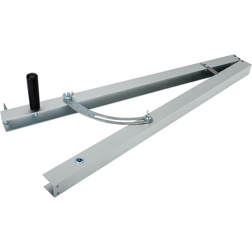
A wood lathe will rotate a long length, but making precise tapers will usually involve just sanding and checking, not much different than doing it with a drill, IMHO. I have the 250 Proxxon lathe, but have found that the drill method works better. Theoretically, a metal lathe would be the way to go, as you can precisely control the the depth of cut and therefore taper. But as mentioned above, deflection of the dowel makes it more difficult than you'd like. And unless you buy a larger metal lathe (VERY expensive), the between-centers distance is not enough for some 1/48 scale masts (although most have hollow spindles that helps accommodate longer pieces).
I'm not sure there is a really good solution to the problem. Every one I know of has problems or limitations, usually requiring guesswork or constant monitoring of diameter along the length. I've used the dowel-in-drill along with a small and large belt sander, and it's worked well for me, but of course requires constant diameter checking. But at least my workbench doesn't have a 100+ pound lathe I have to move.


 ) The greatest advantage of the Chinese stuff is that there's so much reasonably priced tooling available for them. The rule of thumb is that at a minimum you can expect to spend as much to tool up a lathe or milling machine as the machine itself costs up front. You have to watch the "package deals" and compare what you are really getting. A Sherline three-jaw and four-jaw and a tailstock chuck, essential tooling, will alone run you at least five hundred bucks to do anything on their eight- or nine-hundred-dollar lathe, while Grizzly includes a 3-jaw chuck and a tailstock chuck with their combo machine, if memory serves.