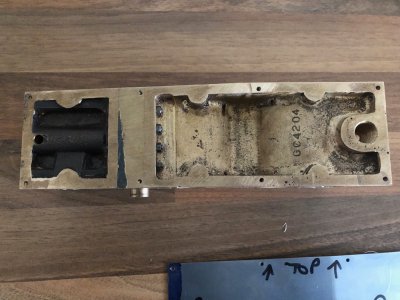
Bolton part eighteen
When I was reading the DRO manual for my mill, I thought I would use the pitch circle diameter function to drill my cylinder covers/block. Seems that whilst I have the buttons for these additional functions, they are not included on my particular model
A bit like when you bought a base model car and there were blanking plugs where electric window switches would be, yes I am going back a few years now
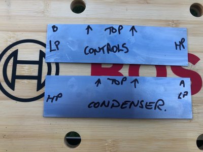
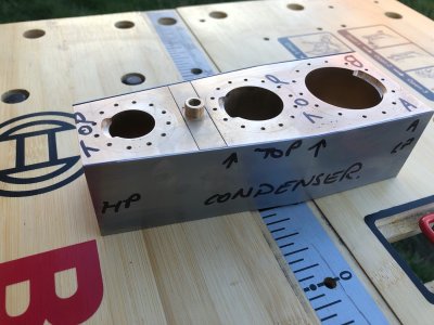
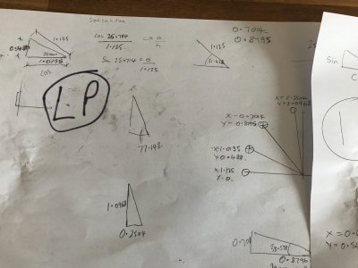
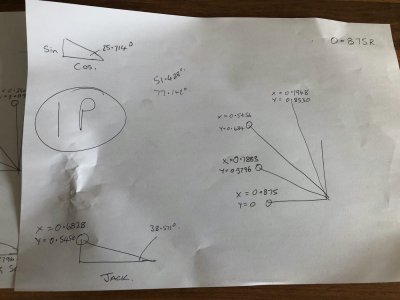
So back to school it felt like for me, I include pictures of my "spider scrawl" just to illustrate Pythagoras had a lot to do with my hole drilling
Using the centre of each bore as my datum I calculated x and y coordinates for my holes. At least I only had to do calculations for one quarter as the rest are mirror images. I could have set the covers up on my rotary table but 14 divisions does not easily divide up 360 degrees, so I knew I would end up with some sort of cumulative error, plus I would still have to drill the block.
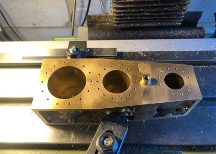
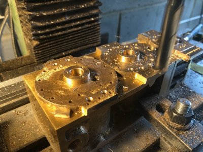
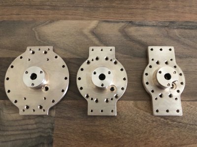
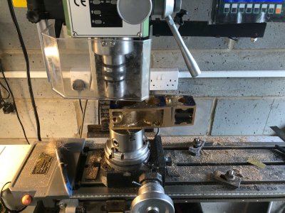
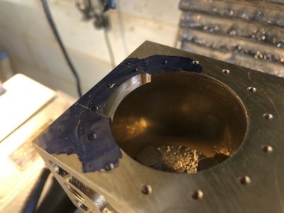
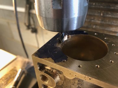
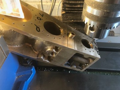
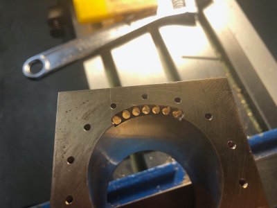
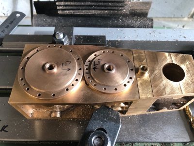
I referenced the inside of one bore at a time using my edge finder and fitted the respective cover with some dabs of medium CA on the flange.
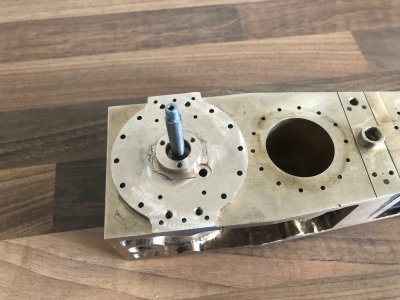
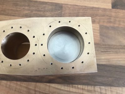
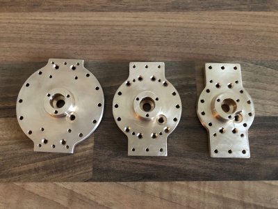
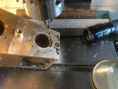
My holes were then drilled tapping size through cover and block to the required depth. The holes were opened up to clearance size in the cover alone using the depth gauge on the quill. The CA was then broken by warming the cover with a blowlamp and the cover removed. The holes in the block were then tapped 7BA.
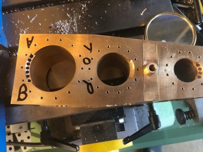
It was tapping the holes for the IP cylinder that disaster/ inevitable happened. My tap broke. Fortunately it snapped just above the hole and on the way out so I carefully managed to unscrew the remaining piece of tap. The tap had done a number of holes and 7BA is only 2.5mm diameter ! I have no doubt I will break some more in the process of tapping the myriad of 7BA holes on this engine.
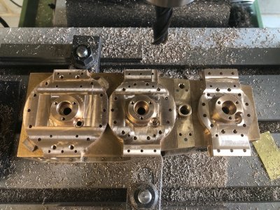
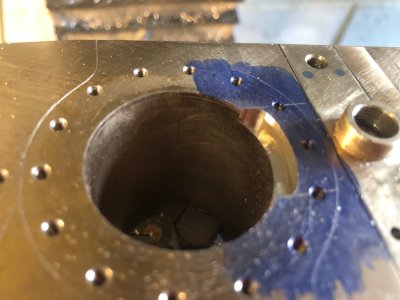
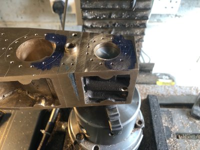
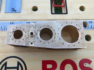
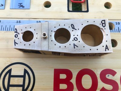
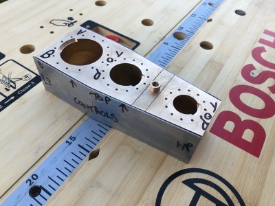
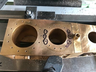
So this stopped play. Another tap has been ordered and the holes with the black circles around them are just a reminder these are still to tap.
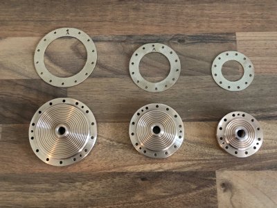
One detail I have added is three " jacking" screws to each cover. On the real engine these are just threaded through the cover and tightening these allowed the mechanic to pop the seal in the gasket. These have been tapped slightly smaller at 8BA which is around 2mm diameter. I will have the challenge later of machining some square head bolts for these holes.
When I was reading the DRO manual for my mill, I thought I would use the pitch circle diameter function to drill my cylinder covers/block. Seems that whilst I have the buttons for these additional functions, they are not included on my particular model
A bit like when you bought a base model car and there were blanking plugs where electric window switches would be, yes I am going back a few years now
So back to school it felt like for me, I include pictures of my "spider scrawl" just to illustrate Pythagoras had a lot to do with my hole drilling

Using the centre of each bore as my datum I calculated x and y coordinates for my holes. At least I only had to do calculations for one quarter as the rest are mirror images. I could have set the covers up on my rotary table but 14 divisions does not easily divide up 360 degrees, so I knew I would end up with some sort of cumulative error, plus I would still have to drill the block.
I referenced the inside of one bore at a time using my edge finder and fitted the respective cover with some dabs of medium CA on the flange.
My holes were then drilled tapping size through cover and block to the required depth. The holes were opened up to clearance size in the cover alone using the depth gauge on the quill. The CA was then broken by warming the cover with a blowlamp and the cover removed. The holes in the block were then tapped 7BA.
It was tapping the holes for the IP cylinder that disaster/ inevitable happened. My tap broke. Fortunately it snapped just above the hole and on the way out so I carefully managed to unscrew the remaining piece of tap. The tap had done a number of holes and 7BA is only 2.5mm diameter ! I have no doubt I will break some more in the process of tapping the myriad of 7BA holes on this engine.
So this stopped play. Another tap has been ordered and the holes with the black circles around them are just a reminder these are still to tap.
One detail I have added is three " jacking" screws to each cover. On the real engine these are just threaded through the cover and tightening these allowed the mechanic to pop the seal in the gasket. These have been tapped slightly smaller at 8BA which is around 2mm diameter. I will have the challenge later of machining some square head bolts for these holes.


