• Win a Free Custom Engraved Brass Coin!!!
    As a way to introduce our brass coins to the community, we will raffle off a free coin during the month of August. Follow link ABOVE for instructions for entering.

The GRACIE S - a Lift Model

waterline or buttock lifts

is one better than the other or is it just a matter of preferences?

the Gracie S is using the buttock lines for lifts a hull using waterlines look like this

half hull.jpg
 
Half models originated as a design tool. Once the information had been taken from them and sent to the mould loft their usefulness ended. Three fates awaited them: being fed to the stove that heated the design office, saved in the hope that they could be used for building a future vessel, or used to decorate the office like Dave’s handsome model posted above.

I have never seen a “working” half model made using buttock lines. Waterline models were usual and with some solid hull half models cut to trace body plan sections. The waterline lifts were not glued together. They would be attached to each other with mechanical fastenings so that once carved the model could be disassembled and each waterline traced.

POB fans will be pleased to know that there was another type of half model. Called a “Hawks Nest Model” it gdconsisted of half breath bulkheads attached to a backboard. Bent around the bulkheads were longitudinal wood strips called ribbands. In addition to holding the model together these ensured that the bulkheads lined up in a fair curve. Each half bulkhead was then traced to takeoff its shape.

The waterline lift model contained all the information needed to loft the hull. While it was necessary to record the location of each body plan section it was not necessary to record the shape of the body plan section. This would be done on the mould loft floor.

In addition to being the basis for the design, the half model was a kind of marketing tool. The shipyard’s customer, who often had his own ideas about what he wanted could easily visualize the shape of the hull, where he might not be able to understand a lines drawing.
 
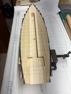
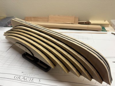
Just a side note, and I know many people already do this - taking pictures and using them to assess your work can allow one to find faults that can / should be corrected before proceeding. In the middle picture above tape marking the keel location is no longer in the correct location between stations 6 and 10 - it had gotten shifted by the clamping operations. While correcting this, I also noted that I could adjust the tape between 28 and 32 a bit on the starboard side. Time to get some shellac and paint out!
 
Shellacked the portions of the hull-block that are now painted. The paint provides information as where to stop removing wood at the sheer as well as where the lifts meet one another - thanks to Bob Cleek for describing this technique to me.

Shaping Boundary Sheer Level.jpg

Shaping Boundary at Lift Intersections.jpg

Next up - a way to securely hold the hull during the shaping process.
 
Greg,
Elegant looking start.

I hope me projecting what I would try from looking at your process so far is OK.

The slope for removal of the lift closest to the keel? I find intimidating. I am not sure how I would do it. It is really acute.
You have it all glued up?
I would use my drum sander to remove the bulk of the transition wood from each layer before I bonded it. Not too close because it is a dynamic curve from one buttock line to the next. A flat facet would be the natural product if the removal is literal line to line.

You have station lines. Now the lines on the lifts will be quickly gone. The lines at the keel and at the rail will remain.
In my drawing program I trace each station's outside shape on its own layer. I cycle the three easy to select colors: RGB for the pattern. #16 = R - #14 G - #12 B - #10 R and #18 G - #20 B - #22 R etc. It is not as important for you to idiot proof the patterns as it is for me, but you never know. And all black can lead to loss of focus. You only have Keel, LWL, and Rail to worry about - no wales no port sills, but I would include those three on each station pattern. With what you are doing also have each buttock line: Black. A base layer has the reference grid.
Each station is a separate layer. I combine (COLLAPSE LAYERS) each station with a copy of the grid. On a canvas that is the size of the printer paper I space each layer. I leave plenty of room outside the pattern before I site the next one. I include the station number for each station. Print.

For GracieS, I think that 5x8 cards are large enough, I glue a three layer ply of the cards using an adhesive that is not water based. Duco works for me.
I glue the pattern for each station on a separate card - again Duco and not the rubber cement I use on frame stock there is no need to remove the pattern when it has done its job. I cut away the inside. Sharp and Blunt's do the job for me.

A gauge for each station and the location for LWL. For GracieS the LWL is a straight line and perhaps a laser line level is a more sure thing but more data is good to have.
 
Last edited:
Greg,
Elegant looking start.

I hope me projecting what I would try from looking at your process so far is OK.

The slope for removal of the lift closest to the keel? I find intimidating. I am not sure how I would do it. It is really acute.
You have it all glued up?
I would use my drum sander to remove the bulk of the transition wood from each layer before I bonded it. Not too close because it is a dynamic curve from one buttock line to the next. A flat facet would be the natural product if the removal is literal line to line.

You have station lines. Now the lines on the lifts will be quickly gone. The lines at the keel and at the rail will remain.
In my drawing program I trace each station's outside shape on its own layer. I cycle the three easy to select colors: RGB for the pattern. #16 = R - #14 G - #12 B - #10 R and #18 G - #20 B - #22 R etc. It is not as important for you to idiot proof the patterns as it is for me, but you never know. And all black can lead to loss of focus. You only have Keel, LWL, and Rail to worry about - no wales no port sills, but I would include those three on each station pattern. With what you are doing also have each buttock line: Black. A base layer has the reference grid.
Each station is a separate layer. I combine (COLLAPSE LAYERS) each station with a copy of the grid. On a canvas that is the size of the printer paper I space each layer. I leave plenty of room outside the pattern before I site the next one. I include the station number for each station. Print.

For GracieS, I think that 5x8 cards are large enough, I glue a three layer ply of the cards using an adhesive that is not water based. Duco works for me.
I glue the pattern for each station on a separate card - again Duco and not the rubber cement I use on frame stock there is no need to remove the pattern when it has done its job. I cut away the inside. Sharp and Blunt's do the job for me.

A gauge for each station and the location for LWL. For GracieS the LWL is a straight line and perhaps a laser line level is a more sure thing but more data is good to have.
More input the better!

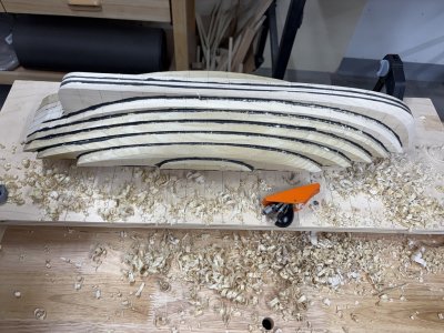
For a good many days, before gluing all the lifts together, I considered partially shaping each lift. In particular, I had thought about doing work on the middle lifts where a great deal of material needs to be removed. Finally I decided that I would glue the lifts prior to any of the shaping. I felt the tradeoff of having a larger / more secure clamping surface for the second, third, ... , pairs of lifts was more important than the ease of removing material first. However, I still could have done work on the middle lifts (and perhaps I should have) because they would not have been affected in the glue-up.

As you mention the hull curvature changes in a continuous fashion and the shaping of each lift is dependent on its neighboring lifts so there is an advantageous in having all glued so that one does not accidentally take to much off a lift before gluing them together. This is particularly the case in the regions where the hull shape is convex - and actually easiest to work on when assembled.

The middle lifts will be a challenge - intimidating, I hope not too much! I will attack the region with a number of tools and expect that a curved gouge will be my friend for a while. Here my biggest concern is that I am able to form a smooth transition between the 2nd set of lifts and the middle lifts without accidently creating a 'valley' before making it to the keel junction.

Yes, a number of gauges do need to be created using the body plan!

I'm hoping to make a building board to secure the hull during the carving / shaping that will also have the station lines marked. This will be a way to keep a coordinate system available for measurements and efficient use of the gauges. Working on such a building board is now my most immediate task for this project.
 
The slope of the hull adjacent to the keel is called Deadrise because it is the rise of the hull at its Dead Flat. Carving a pair of half hulls makes this easy if you have a sliding bevel gage:

Find the dead flat on your drawing. It’s usually marked by a symbol. ( a circle with two half circles back to back). It should be the widest hull section on your body plan.

Draw a line on your body plan at the dead flat rising from the garboard, and tangent to the hull’s deadrise.

Set your bevel gage with the wooden part against the hull’s centerline and the metal blade along the rising line that you drew.

Mark the location of the dead flat section on each layer of your stack of lifts.

A plane is probably the best tool to begin removing material using your bevel gage as a guide.

This procedure will result in a straight deadrise at least as wide as the body plan section. Convex or concave areas can be carved next using templates.

Roger
 
Find the dead flat on your drawing. It’s usually marked by a symbol. ( a circle with two half circles back to back). It should be the widest hull section on your body plan.
The dead flat is not explicitly marked on the plans for Gracie S.; however, it is most likely associated with station 14.
 
I have an idea for a building board:

At HomeDepot I asked about plywood sizes. I needed 1/2" for the shaping table project. They have 2'x4'. I had one bisected to 2'x2' a size that I can manage and will fit in my Z (which is not much of a truck). While I was at it, I had the same done to a 2'x4' sheet of 3/4" ply to have in case.
This baseboard is a case.
My plan: Cut a 12" x 15" rectangle of 3/4" ply.
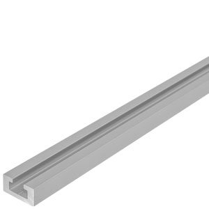
I fell for a sale years ago and bought 10' total of mini T-track.
T channel.jpg
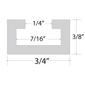
It is 3/4" wide and 3/8" deep.
T cross section.jpg
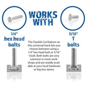
It uses 1/4" 20 TPI bolts in the track.
T bolts.jpg
They want you to use these, but even a 1/4" flat head bolt will work running in the track. HomeDepot calls them "screws".

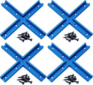
Because it looks cool in the demo pix , I will put a crossing track with 3" arms in each of the four corners.
cross track.jpg
No routing of channels! I will both screw and epoxy bond the track on top of the 3/4" board.
Now for the clamping part: In the middle = fix two parallel long tracks that are 3" apart. Two 15" tracks - each one piece at the long axis (north/south)
Two parallel 3" apart tracks in the middle 12" long (east/west).
Each of the east/west tracks will have to be five short segments. The four corner "+" tracks will need long tracks connecting them.
There will be four parallel tracks running north/south and four east/west.
The short pieces are OK as is, but the north/south tracks will need their walls cut away where the east/west tracks butt against them.
I bought a 4.5" 3/8" arbor Genesis blade that says it cuts Al to cut track into segments ad cut away walls. It should fit on my Jim saw. The same size Diablo 26 teeth blade fits.
I will mill a piece of a Pine 2x4 to be 3/8" thick and PVA bond blocks of it between the tracks to make the top flush.

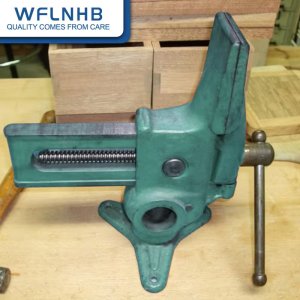
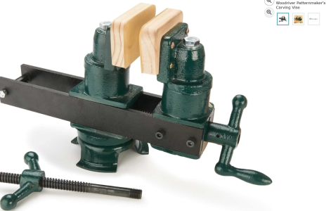
I plan to use 1/4" or 1/2" thick Hard Maple to make the jaws of a vise fix them to an apron at the back of the jaws for bolts running in the track.
It should not be difficult to make something that grips the model and runs in the tracks There are lots of areas on the 15x12 surface to place the model.

A thin sheet of steel and be epoxyed to the underside of the plywood base and work as a base for tools with magnet grip.

I do not know just what I would clamp down or from the side, but as is , screwing and unscrewing these guys every time seems like it would get old.
I am imagining that tixing one to a small board that also has a 1/4" hole for a track bolt would allow it to slide lots of places and be fixed there.
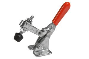
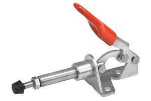
T mini_toggle_300.jpgT mini_push_toggle_300.jpg

I see lots of tools that can be screwed to a board that can be fit to a 1/4" bolt and can them have a solid base.

If per chance the 3/4" [;y is not stable enough these Milescraft clamps go into the track and clamp to the bench
Milescraft-Tee track clamps.jpg

Just thinking
 
Here's my T-track try from a while back - I had bought the metal pieces for a low cost on Banggood! The rails were screwed to the board, nothing fancy.


2020-05-10 16.01.57.jpg
 
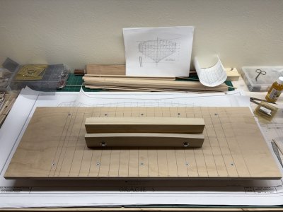
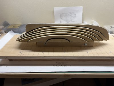
I fabricated a carving board for Gracie today. The top is a sheet of 3/4" plywood; under there is a frame to keep the plywood flat and make it easier to lift / move the setup. The centerline and station lines have been scribed into the top and then gone over with a pencil. Station lines are labeled on both sides of the board. The structure in the center is made from 5 pieces of wood. The middle piece is an inch thick and fits in the recess that was cut into the middle lifts. The recess had been cut along the LWL and this made it easier to have this setup hold the hull level with the LWL (and keel as well). The outermost boards match the deck sheer and provide additional support to the hull - they were made from offcuts that resulted when the middle lifts were cut out. Between the contoured outer boards and the middle 'plug' are spacer boards. This was done to broaden the region of support. The plug is not permanently attached to the board; rather it is bolted to the rest of the support unit. The plug is removable should a time come that I would want to place the plug in a vise to hold the hull at a different angle than the board can provide.

1763780450322.jpeg

Here is Gracie (not a turkey) on the carving board - set about 2 inches up so there is space to work near the sheerline. Also, there is space to align gauges along station lines efficiently.

1763781154180.jpeg
 
Back
Top