• Ships of Scale has incorportated an extra level of security when you log In. Please follow on-screen prompts to acknowledge that you are not a robot via a "Check Box" or a "Pictorial Check Box Puzzle". This is needed due to higher level of AI Activity Security.
  • SUBSCRIBE TO SHIPS IN SCALE TODAY!

    The beloved Ships in Scale Magazine is back and charting a new course for 2026!
    Discover new skills, new techniques, and new inspirations in every issue.

    NOTE THAT OUR NEXT ISSUE WILL BE July/August 2026
  • Win a Free Custom Engraved Brass Coin!!!
    As a way to introduce our brass coins to the community, we will raffle off a free coin during the month of August. Follow link ABOVE for instructions for entering.

JAMES CAIRD 1916 - Modellers Shipyard - 1:20 scale

Joined
Dec 7, 2022
Messages
213
Points
113

While my primary modeling preference has evolved to scratch-building, I am still willing to build kits for others. In many cases I don't present the work in forums; however, here I do find a compelling reason. The James Caird famously provided safe passage for Ernest Shackleton and a five others on a 17 day, 800 mile voyage from Elephant Island to South Georgia in horrendous conditions. This, in turn, led to the safe rescue of all of Shackleton's crew from the ill-fated exploration aboard Endurance. I was asked to build a model of James Caird for a collector. We eventually agreed upon an out-of-the box version based on the Modellers Shipyard offering. To my knowledge this is the only available kit for the James Caird.

Also, to my knowledge, there is but one build log (on SOS/MSW/DDM) for James Caird - a well researched scratch-built model by Seamus107. I highly recommend that anyone interested in building a model of James Caird - from kit or scratch - take the time to explore his work. In fact, background information on the boat is so well covered there that there is no need to add anything here. But from time to time, I will be referencing his log. https://shipsofscale.com/sosforums/threads/james-caird-1-24-scale-scratch-built.5674/ . This work was written primarily in 2020, a while before the Modellers Shipyard kit was released. Seamus107 was actually interested in someone creating a log for the kit and I don't beleive that this had been done. Thus my reason for doing so - an overview of what the kit delivers and an opportunity to see ow the kit compares to a scratch-built effort.

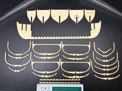
Here are some of the kit contents. There are 3 sheets of laser cut plywood as well as some strip wood and dowels along with a number of accessories. More about all of the components as they are needed for assembly.
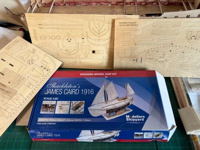
James Caird Kit Contents.jpg
 
The instructions are heavily picture based and there are no full-size plans for the model and/or components. I scanned all of the laser cut sheets in the event a piece was destroyed / needed to be remade along the way.

It is suggested that frames, false keel, and filler blocks are released from the sheets in an understandable order. The frames and filler blocks have laser engraving that indicates bevels needed to fair the hull. The pieces do release easily with a sharp knife, which I also used to bevel the frames. There is not much to the frames, so care is needed not to break the pieces. I'm not a fan of plywood, but I assume that this material was chosen so that the frames would have a lower chance of being broken during processing and assembly. The major downside is the less than attractive edges.

Nevertheless, all of the pieces were successfully processed.

Hull Structure Components.jpg

I assembled the pieces in an order that deviated a bit from the instructions and also, while not being directed to do so, made use of the so-called 'bulkhead cap' to align the pieces. There are good opportunities to end up with a skewed structure if care is not taken.

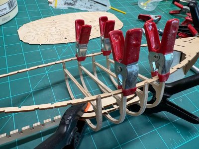
The five solid bulkheads were installed first. The full frames - starting mid-ship, came next. In the picture below, the four most central (and sturdiest) frames are being added. The bulkhead cap is being used for alignment and a piece of wood clamped along the keel region is also helping out in this regard.

Installing Full Frames.jpg

Once the nine frames that intersected with the cap were installed, the bow and stern filler blocks were added. Not following the instructions, these pieces were not pre-beveled. My reasoning was that without the bevel, I could more securely clamp the pieces in place during assembly. Once they were in place with glue cured, they were faired to the previously installed pieces and the pre-marked bevel lines. At this time a check was made on any additional needed fairing of the full-frames and bulkheads. I will note that the kit designers had done a fine job with the pre-bevel lines and very little adjustment was now needed.

Filler Block Fairing.jpg

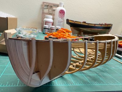
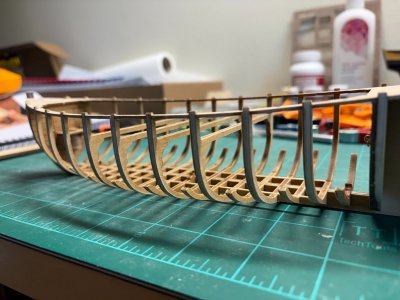
Finally the partial frames were added - a couple at a time using the so called 'frame braces' to help insure alignment. With these delicate pieces in place another check was made as to the fairness of the structure. When all was deemed good it was said to be ready for the first planking.

Frames in Place and Ready for Planking.jpg
 
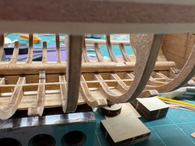
I should have noted in the previous post, that at this stage, there is already a good opportunity to compare with the work of Seamus107 - in particular, note how many more frames are in his model and also note how much finer their structure is. Also, the 'frame braces' seen before are fictious - fortunately they will not be visible in the completed model.

Moving on to the first planking. This planking is done with 1mm x 4mm limewood strips. The provided material is as good quality as can be expected in a kit. With that said, 1mm thick material is pretty thin and if the underlying hull structure was not faired correctly, the planking process would certainly fail. Truthfully, there is little margin for error.

As with all kits that provide stripwood for planking, there is little hope for anything resembling a nice run of planking top-to-bottom. It always seems to be fight to make due. The instructions ask that three un-tapered strips are secured starting at the top of the frames / bulkheads and moving down. Next six un-tapered strips are added from keel going up. The gap between these two groups of planks are then to be filled with 'wedges'.

Using white glue, the three upper strips went on well. It is really important that the strips are glued edge-to-edge as well as to the frames / bulkheads. If not, due to the flexibility of the strips, smoothing will be somewhere between difficult and impossible. I then went to work on the lower strips which I expected to be more of a challenge. I managed to get four strips in place based on the instructions, but no more. Already with the fourth strip, the amount of edge bending was past anything desirable. So instead of forcing the issue even more, the fifth strip was allowed to take a more natural run and a 'wedge' was used to fill the resulting gap. The sixth strip then went on fairly easily.

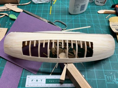
Finally the filling wedges were added. They went in close to as described - but not exactly! Nevertheless, the result was not terrible for a kit. Below is what it looked like before any smoothing. With 1mm thick material, the planking needed to be as continuous as possible even before the contouring. There is a large opening port and starboard to look inside the boat. The top will be mostly sealed with little internal viewing opportunity.

First Planking Complete.jpg

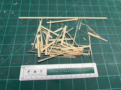
At this point I will note that it is important not to make errors with the planking wood supply - there really isn't much left over, when the process is done. I feel that the kit should have included a few more strips in case of fabrication error and / or pieces of lower quality that could not be used. Fortunately, I found enough satisfactory material to get the job done - but is was close! Here is what was left from the provided stock:

IMG_4825.JPG

Going forward - there is the same amount of material provided for the second planking.

I've carefully sanded the first planking smooth. This was accomplished using 180 and 220 grit sandpaper. Light was not close to the structure when the picture below was taken, nevertheless, one can judge the thinness of this planking!

First Planking Smoothed and Ready for Second Planking.jpg

This represents just under 2 weeks of work on the kit. More later!
 
Nicely done! Small craft like these can be hard to build as their very thin scantlings do provide rigid support of planking like the sawn frames of larger vessels. And, it looks like this kit does it the hard way. Using those tiny frames to support planking going forward requires a Light touch and steady hand. I would have been left with a pile of broken parts.

Actually Seamus 107’s scratch building method looks like an easier building method.

Roger
 
Perhaps you could laminate a very thin piece of wood strip over the plywood edges.
Bryian -

Yes this is a possibility - certainly one that I will use for the keel. As far as for the frames, the strip would need to be extremely thin so that the frame still looks to be behind the planking. I do have some thin C. Boxwood left over from a previous model - it is 0.3mm thick, about as thin as I can realistly make in my thickness sander.

Greg
 
Actually Seamus 107’s scratch building method looks like an easier building method.
I've gotten to the point that every scratch build effort is easier than any kit I need to work on. Its easier for me to fabricate the parts so they fit correctly as opposed to finding a way to get the provided parts to mess properly. Nevertheless, I think that I have already made it past the most fiddly aspects and with care this model does seem to be one that can be successfully assembled in a relatively short amount of time.
 
For those interested, the original James Caird was brought back to England , I believe by Argentina who were so impressed with the journey. The James Caird is now located at Dulwich College in south London and is available for a tour just one day per week but rebooking is necessary
 
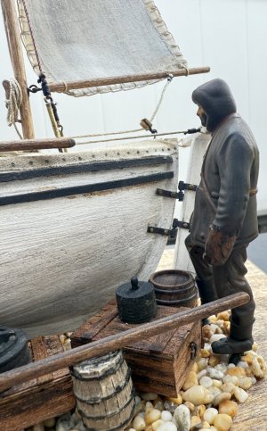
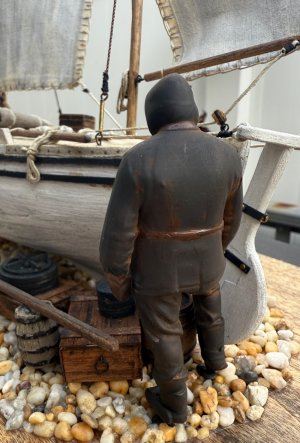
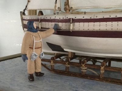
Kmgwood and Seamus - I really like the figures that you placed by your respective models! Also, from the first time I saw it, I think the sled Seamus uses to mount / display his model adds a lot to the presentation.

A couple of accomplishments this week. First the mast step was cut into a dowel and then mounted above the keel. This piece is identified as 'hog-back'. My understanding is that this is a spar / mast that was retro fitted and installed in James Caird to prevent the boat from developing a hog-back; i.e., bent keel structure.
Mast Step in Place.jpg

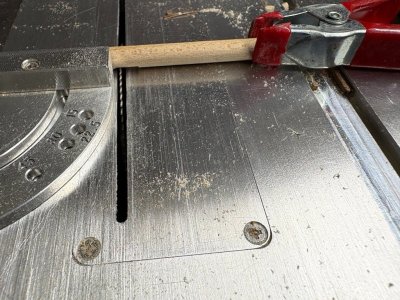
I'm sure you can do just as well using lower cost / tech tools - but I do have a small table saw and I do use it. I set the blade height to 1.5mm (the desired depth of the step) and made many passes on the saw until the step was opened to the proper dimensions. I used a clamp on the end of the dowel to prevent rotation during this process.

Mast Step Being Fashioned.jpg

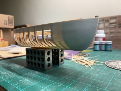
More importantly, I have attached the second layer of planking. This layer is very thin, just 0.5mm thick. For a good result, the first planking needs to be smooth and the second layer must be laminated tightly to it. If this is not done, the final smoothing process will go straight through the second planking. The instructions suggest using contact cement for this step. I am not fond of that type of cement for this purpose and chose to use Titebond (yellow woodworks) glue. A thin layer does not have too much water and can be pretty tacky right away (unlike white glue). So I cut the planking material close to the final length, apply the glue and put the piece in place. I then rub / burnish the plank until I am sure it will not move from the desired location.

I should have mentioned, that before the second planking commenced the keel was glued in place. This process in not hard at all; however, the fit is not quite as tight as one might like. This is because the keel and false-keel pieces are separated by a laser cut; hence there is a gap between the two pieces that matches the width of the cut. On the plus side, the general shape match is great as would be expected!

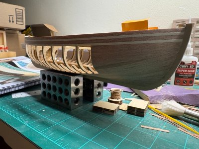
Here's what it is looking like now after a very light sanding with 180 grit sandpaper. I'm not convinced that filler / wood putty will be needed as shown in the instruction booklet. [Super glue not used!]

Second Planking.jpg
 
Back
Top