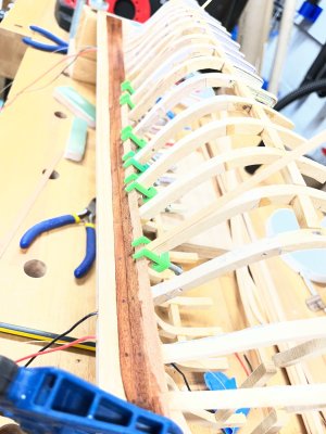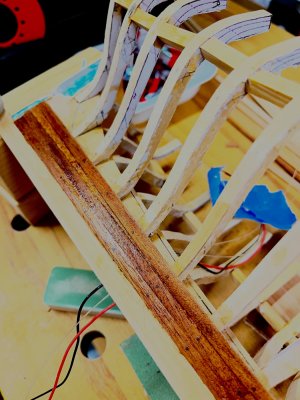



• Ships of Scale has incorportated an extra level of security when you log In. Please follow on-screen prompts to acknowledge that you are not a robot via a "Check Box" or a "Pictorial Check Box Puzzle". This is needed due to higher level of AI Activity Security.
  • SUBSCRIBE TO SHIPS IN SCALE TODAY!

    The beloved Ships in Scale Magazine is back and charting a new course for 2026!
    Discover new skills, new techniques, and new inspirations in every issue.

    NOTE THAT OUR NEXT ISSUE WILL BE July/August 2026
  • Win a Free Custom Engraved Brass Coin!!!
    As a way to introduce our brass coins to the community, we will raffle off a free coin during the month of August. Follow link ABOVE for instructions for entering.

Planking Confusion

Joined
Jul 12, 2023
Messages
130
Points
78

Can someone please give me advice? Firstly please see my plans…..
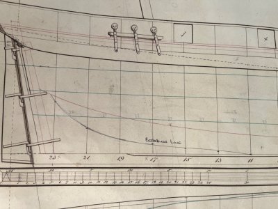
IMG_3648.jpeg
The line parallel with the top of the keel runs forward and up the bow. I think this is the rebate for the forward planking.

At the stern this runs out as shown between frames 17 &19.

On the model, see next photo……
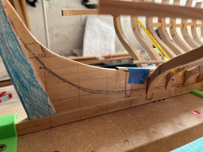
IMG_3649.jpeg
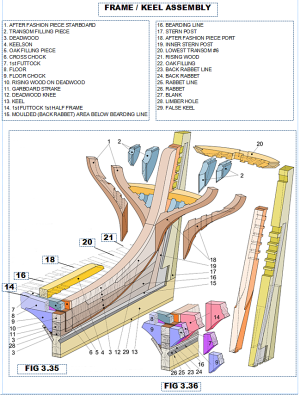
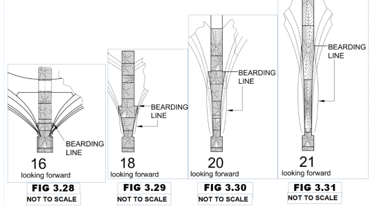
The half frames will be ground/sanded back to the bearding line as pencilled on the stern deadwood.

The question does the planking ease out of the rebate and then follow the stern post to the very end thickening the stern post at the rudder, or does it stop short at the two straight lines in the blue shaded area. Alternatively does the rebate continue up the deadwood and the planking turn into this? Are there then short straight planking from the rebate to the end of the stern post?

Please can someone provide a photograph of this area of a part completed or finished model? The vessel is c1830.

Thanks in advance……Seagull
 
Here goes my shot at this:

At the keel -- between 10 & 11 the top (lighter) parallel line is the top of the keel and the bottom of the frame. The lower (dark) line is the rabbet for the garboard. just a starting point for the changes going aft from here.

Starting at 11 the bearding line is the bottom of the frame. The deadwood starts wide and stays wide until the bearding line. At the bearing line the thinning (adz work) comes out of the deadwood -

The keel at the sternpost is much narrower than it is even at the gripe - The whole part of the keel - deadwood unit becomes almost delicate in how much thinner it becomes. No vertical timber (frame) could stand being so thin - so the deadwood has to do the job.

The angle of the taper is enough horizontal that the rabbet is needed until 19. After 19 the angle is so acute that the top of the keel is the rabbet.
Now - to my eye - the angle where the rabbet feathers up to the top of the keel is too abrupt - I see a longer transition - at least on a model.

The sternpost: the inner black line is where the outer face of the planking merges into the sternpost.
The false sternpost is two timbers and they are subject to being one long rabbet - adzed thinner and thinner - it almost scares me just how thin it seems relative to the top of the deadwood.

At 11 the frame goes too far down. At 13 the same but even more. At 15 a whole lot too far down.
 
Thank you both for your reply contributions. Allayed the diagram is useful, though I confess my model appears less complicated at present though I did think some floor chocks would be needed to support the Garboard. On the diagram I cannot make out where the Garboard and other planking would run out moving towards the stern.

DA Warden (Jaager), thanks for the observations I intended to adze back the trailing lower edges of the frames to cut in the rebate and allow the Garboard passage towards the stern. Incidentally these were put lower to the width, centreline and height of the topsides were to drawing (I hope!). If I understand your comments I should take the rebate vertically to the top of the sternpost and chamfer this back to allow the planking through and nestle flush in the stern post rebate. Is that correct? I will also attach some wood to the deadwood sides to support the planking.

Any further feedback and comments/photographs greatly appreciated.

Thanks again…..
 
Last edited:
If I understand your comments I should take the rebate vertically to the top of the sternpost and chamfer this back to allow the planking through and nestle flush in the stern post rebate. Is that correct? I will also attach some wood to the deadwood sides to support the planking.

The surface of the planking melds into the sternpost. until it hits the wing transom where the run of the planking is mostly horizontal and end grain may show - depending.
The garboard runs along the top of the keel and melds into the sternpost.
THE TOP EDGE OF THE GARBOARD IS ALWAYS STRAIGHT, IT IS NEVER EDGE BENT. ANY TRIMMING COMES FROM THE BOTTOM.
THIS IS IMPORTANT AT THE BOW. THE GARBOARD NEVER BENDS UP. At the sternpost - the last section of the garboard may be actually a wedge. If the width of planking to cover the distance from keel to wing transom is significantly wider the the rest of the bottom a contribution from the garboard may be necessary.

The surface of the planked bottom should be a continuous plane from the side of the sternpost going forward. And from the side of the keel -over the garboard and the strakes going up to the wale.
The planking was not made thinner, Whatever wood that needed to be removed was taken from the deadwood. It was getting dangerously thin at the sternpost.

Look at your Body plan. The left side - the aft side. Look at how close to the center line the shape of station 21 and 23 gets. This is how thin the deadwood is at that station.
Thin long wedges of wood would be needed if the actual frame timbers provided planking support. This is near impossible to do and is too weak.
This is why there is deadwood and its bearding line.

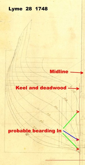
Lyme demo.jpg

Probably not the best example but look at how far in 115 is from the bearding line to the top of the keel.

You should probably make molds to gauge just how much wood to carve out of the deadwood at each station and do the intervening transition
This defines the after shape.


To scramble your brain even more - You have a complete deadwood running fore and aft. Because of this you have to use half frames at the deadwood.
I do not mess with any half frames or any cant frames. I use full frames all the way. The upper deadwood is vertical strips in the spaces between the frames. The fore and aft oriented run of deadwood starts at the bearding line. My keel - stem - deadwood sternpost go in last.
 
Last edited:
I can't even figure out what ship is being described here? And if a scratch build, where do those wonderful drawings and 3D view come from?
 
I can't even figure out what ship is being described here?
Seagull as not posted that information.
Curious angle on the stays. I suspect a large boom. The mast has a serious angle.

Lyme 28 1748 - Unicorn class is just a random pick for an example that should match what Seagull has on his plan.
 
Thanks again for all of the information…..

Signet….. I am researching the people, places and events in the “life” of HM Packet Seagull (1829 proposals to 1852 its decommissioning). Please feel free to follow my build (out of my depth therefore lots of help from SoS forum experts) the historical research and other things along the way.

Best regards…..Seagull
 
Hi here to my regular followers and also the experts who continue with their help and guidance. Things are, at least for the moment going well! (Hope I haven’t spoken too soon).

Went to Falmouth a couple of weeks back and continued the research on the Seagull packet ship. Took some photos for the book I am writing (currently being in draft form) and visited the Bartlett Library at the National Maritime Museum Cornwall to access their data base. Discovered another very interesting incident involving this vessel. I am beginning to conclude that as one of the least mentioned packet ships it has the richest history of any of the vessels around at that time.

Trying to identify the owner of the Seagull painting by Nicolas Matthew Condy (Nicholas Condy the Younger) currently at a dead end!

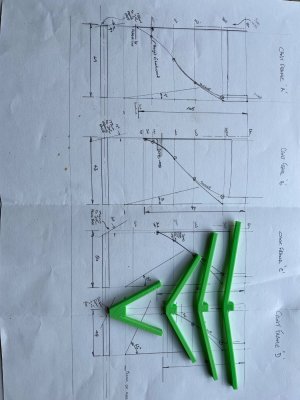
On the build, I have lifted the can’t frames …..IMG_3738.jpeg

But the forward one appears so extreme I have started to plank the lower part of the hull to provide more rigidity whilst working and to give a better datum to the troublesome cant frame. Planning on moving to the stern shortly to get that completed before starting on the internal features, the mast steps and the bilge block.
IMG_3754.jpegIMG_3753.jpegA
 
Back
Top