• Ships of Scale has incorportated an extra level of security when you log In. Please follow on-screen prompts to acknowledge that you are not a robot via a "Check Box" or a "Pictorial Check Box Puzzle". This is needed due to higher level of AI Activity Security.
  • SUBSCRIBE TO SHIPS IN SCALE TODAY!

    The beloved Ships in Scale Magazine is back and charting a new course for 2026!
    Discover new skills, new techniques, and new inspirations in every issue.

    NOTE THAT OUR NEXT ISSUE WILL BE July/August 2026
  • Win a Free Custom Engraved Brass Coin!!!
    As a way to introduce our brass coins to the community, we will raffle off a free coin during the month of August. Follow link ABOVE for instructions for entering.

Position of Scuppers

Joined
Nov 6, 2019
Messages
734
Points
403

Location
Sunshine Coast Queensland Australia
I am puzzled by the position of the scuppers on 18th century frigates (such as Boreas, Enterprise etc).

Online searches confirm my understanding that they discharge directly at the gun deck level but most models show them discharging just above the wales. To me, this must mean that those that discharge below the level of the gun deck must be piped downwards to exit somewhere about the lower deck.

The RMG has an image that seems to confirm a downward pipe but not enough detail to show where it discharges.

Any help greatly appreciated.

 
The downward discharge is correct. I doubt that there was a firm rule as to how far below the deck they discharged, and it probably varied across ships, but about 18 inches is reasonable, so long as the discharge part does not puncture a wale.
 
I am puzzled by the position of the scuppers on 18th century frigates (such as Boreas, Enterprise etc).

Online searches confirm my understanding that they discharge directly at the gun deck level but most models show them discharging just above the wales. To me, this must mean that those that discharge below the level of the gun deck must be piped downwards to exit somewhere about the lower deck.

The RMG has an image that seems to confirm a downward pipe but not enough detail to show where it discharges.

Any help greatly appreciated.

This is the result if the scuppers discharge straight through the hull from the gun deck. They are usually shown in the black paint line above the wales. Which is correct?
The downward discharge is correct. I doubt that there was a firm rule as to how far below the deck they discharged, and it probably varied across ships, but about 18 inches is reasonable, so long as the discharge part does not puncture a wale.
Thanks Charlie
I guessed I was wrong and I should have asked on here before drilling the 4mm holes. The ones I had there from a long while back were less than a mm and barely noticeable.
I'll leave it for now but will have to correct it eventually.
The joys of working too late at night
 
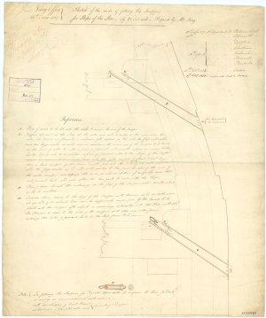
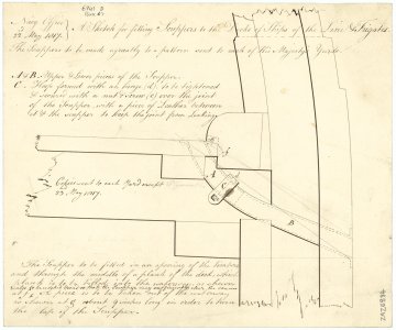
There are drawings on cross sections at RMG that may help. Two examples follow:
Allan

1788002414516.jpeg
1788002454748.jpeg
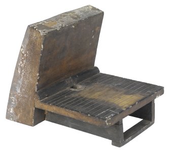
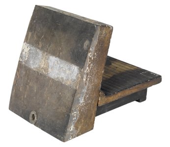
There is also at least one model showing the scupper
1788002482112.jpeg
1788002498244.jpeg
There are also drawings and detailed explanations in Goodwin's The Construction and Fitting of the English Man of War on pages 208-209. It includes the number and size for various size ships.

I looked at a lot of photos of contemporary models and was very surprised not one of them included scuppers. I would guess there must be at least one, but I could not find any.
 
Thanks for posting Allan; interesting. Just to reassure Ian, I should perhaps point out that the waterways shown are 19th century style, and that before these they were a hollow curve, with the mouth of the scupper cut into the curve, rather than the flat of the deck.

The long downward angle of the discharge pipe was probably chosen to reduce the chances of seawater flowing up to the deck.
 
There are drawings on cross sections at RMG that may help. Two examples follow:
Allan

View attachment 630498
View attachment 630499
There is also at least one model showing the scupper
View attachment 630500
View attachment 630501
There are also drawings and detailed explanations in Goodwin's The Construction and Fitting of the English Man of War on pages 208-209. It includes the number and size for various size ships.

I looked at a lot of photos of contemporary models and was very surprised not one of them included scuppers. I would guess there must be at least one, but I could not find any.
Thanks Allan,

Yes, I did see those RMG images, but long after the event. My mistake began several years ago when I went to a lot of trouble (without sufficient research) to install tiny scuppers through the hull at gun deck level - Post #158 of 10 January 2022. They were so small I doubt anyone noticed they discharged too high.

Late the other night I had the 'brilliant idea' of pushing the old ones back through with an awl and replacing the outer profile with the scale equivalent of 8" scuppers. Hence the Makita drill and what we can no longer hide.

Rather that change the line of the black paint above the wales, I will bite the bullet and remove the new ones, placing them lower where they should be. Once again, I should have followed Olha's lead .....

Thanks for taking the time to respond.
 
Thanks for posting Allan; interesting. Just to reassure Ian, I should perhaps point out that the waterways shown are 19th century style, and that before these they were a hollow curve, with the mouth of the scupper cut into the curve, rather than the flat of the deck.

The long downward angle of the discharge pipe was probably chosen to reduce the chances of seawater flowing up to the deck.
Thanks Bilge Rat,
See my reply to Allan above. Now to see how good I am at repairing broadside damage to the hull.
 
Back
Top