• Ships of Scale has incorportated an extra level of security when you log In. Please follow on-screen prompts to acknowledge that you are not a robot via a "Check Box" or a "Pictorial Check Box Puzzle". This is needed due to higher level of AI Activity Security.
  • SUBSCRIBE TO SHIPS IN SCALE TODAY!

    The beloved Ships in Scale Magazine is back and charting a new course for 2026!
    Discover new skills, new techniques, and new inspirations in every issue.

    NOTE THAT OUR NEXT ISSUE WILL BE July/August 2026
  • Win a Free Custom Engraved Brass Coin!!!
    As a way to introduce our brass coins to the community, we will raffle off a free coin during the month of August. Follow link ABOVE for instructions for entering.

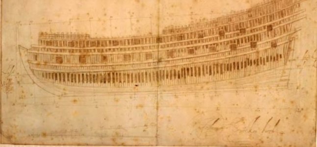
New design Le Saint Philippe -1693 - 1:48 by Trident Model Update 0926

Yeah, revising already done stuff is somehow painful! Good job!
To me, this isn't just a kit — it's a tribute. I didn't want to approach it with a "designing a product" mindset. Instead, I wanted to pour everything I have into restoring this ship — because I believe that's the greatest respect I can show it.
 
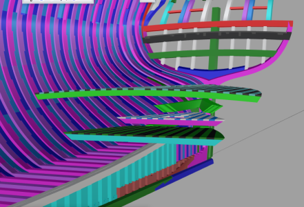
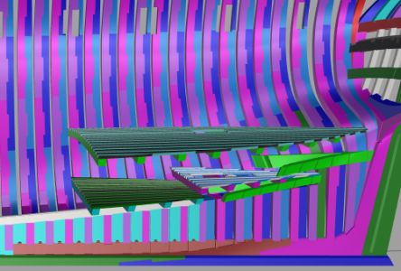
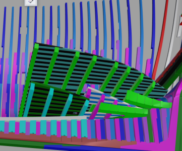
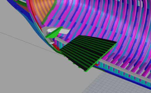
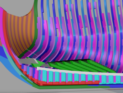
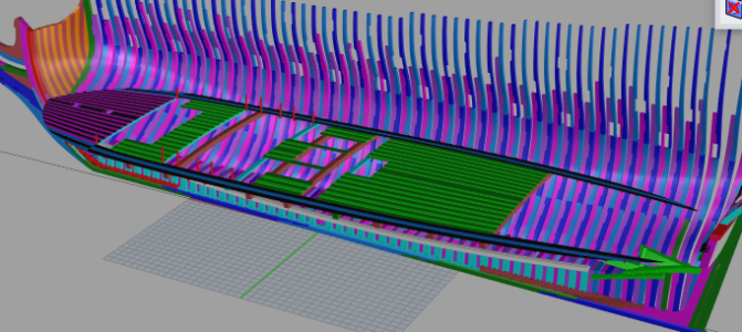
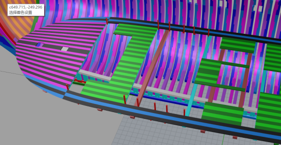
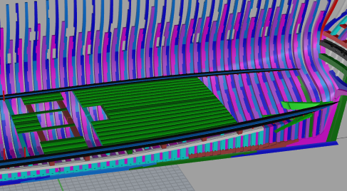
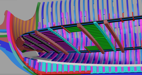
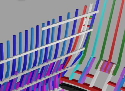
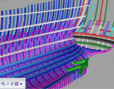
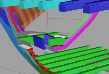
"Hello everyone! Today I'm sharing an update on the lower deck. To be honest, this part turned out to be much more complicated than I had anticipated. During the process, I constantly referred back to Mr. Michele Padoan's build log, which gave me a lot of inspiration. The 'Saint-Philippe' is by far the most complex ship I have ever tackled, and I really hope I have passed the most difficult bottleneck."

1.png

2.png

3.png

4.png

5.png

6.png

7.png

8.png

9.png

10.png

12.png
 
May I ask what software package you use to design the model? I am interested in learning some form of CAD program that will enable me to design a hull form from scratch, with only known dimensional parameters as my guide. I want to show the complete timbering of the structure. Ultimately, I am hoping to produce a full, printed plan set and published monograph. I’m just unsure of what the best software is for that application, which isn’t too complicated to learn. With luck, I’ll be able to take free continuing ed classes, locally. Time is on my side, here.
 
May I ask what software package you use to design the model? I am interested in learning some form of CAD program that will enable me to design a hull form from scratch, with only known dimensional parameters as my guide. I want to show the complete timbering of the structure. Ultimately, I am hoping to produce a full, printed plan set and published monograph. I’m just unsure of what the best software is for that application, which isn’t too complicated to learn. With luck, I’ll be able to take free continuing ed classes, locally. Time is on my side, here.
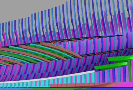
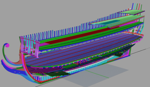
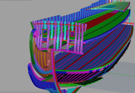
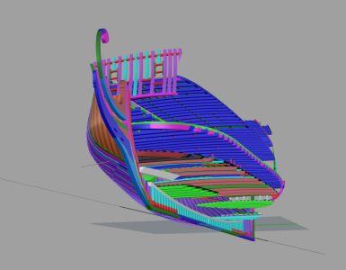
Hubac's Historian, nice to talk with you! Regarding drafting/modeling, there are actually many software options that can achieve the effects you're looking for. For hull design I use Rhino—all the screenshots you saw above were created in this software. For sculpting I use ZBrush. Wishing your project all the best!
 
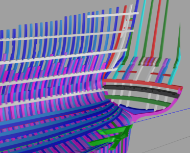
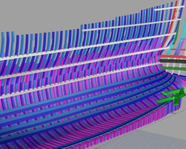
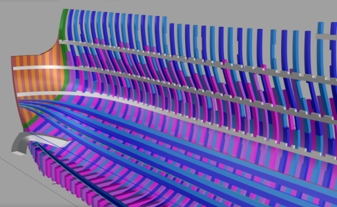
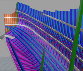
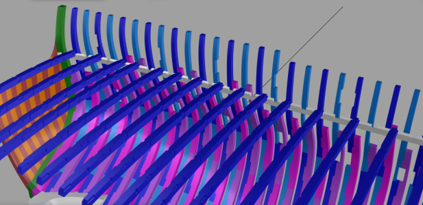
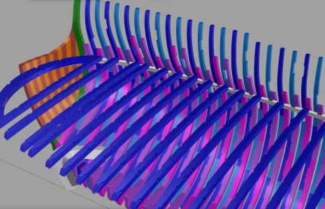
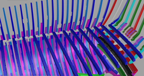
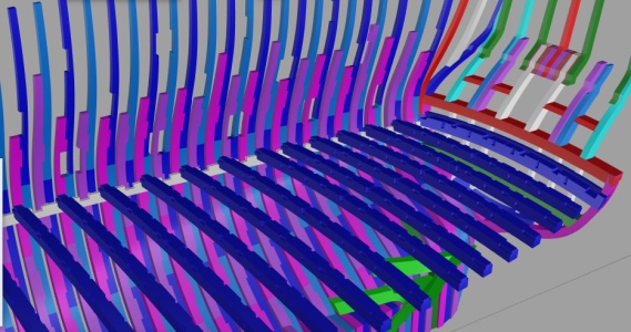
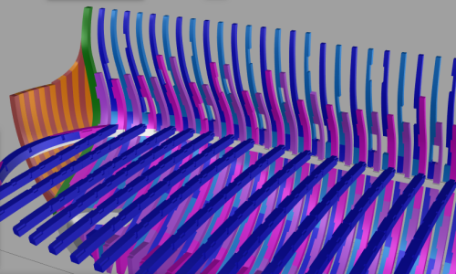
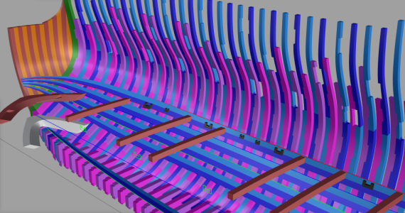
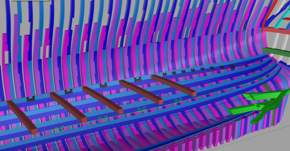
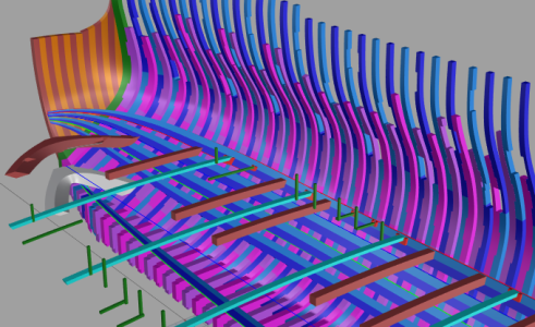
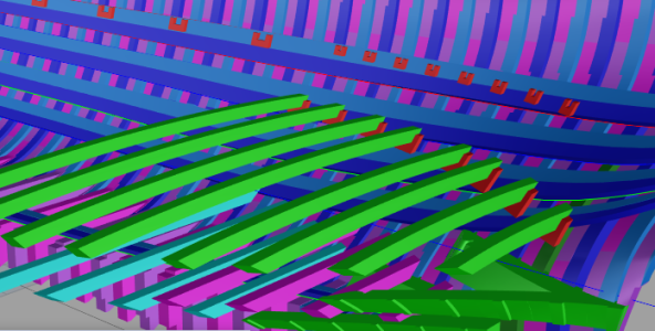
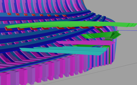
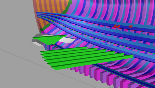
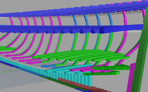
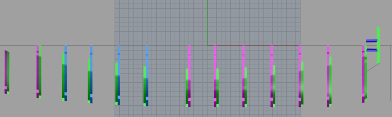
Hello everyone! This update showcases the details of the side beams and part of the inner hull. As shown in the photos, the details presented are the final configuration—what you see is what you get, nothing more, nothing less. If you have any questions about the details, feel free to reach out. Thank you all for your support and interest!

1.png

2.png

3.png

4.png

5.png

6.png

7.png

8.png

9.png

10.png

11.png
 
So, one of the things that I don't fully understand about the framing of a ship of this time period is whether the frames are set perpendicular to the keel, or the waterline - in consideration of the 2-3' or so difference in displacement fore and aft.
 
So, one of the things that I don't fully understand about the framing of a ship of this time period is whether the frames are set perpendicular to the keel, or the waterline - in consideration of the 2-3' or so difference in displacement fore and aft.
Great question! For ships of this era, all frames are built perpendicular to the keel as the primary reference. The 2–3 foot difference between fore and aft displacement creates hull trim, so the frames are naturally not square to the waterline. That is how the original lines plan defines the framing.
 
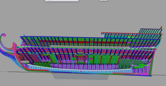
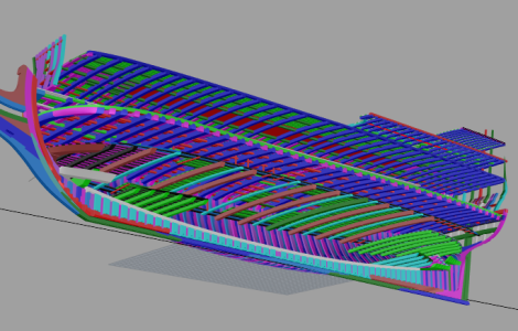
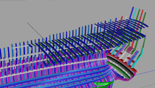
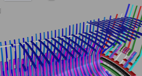
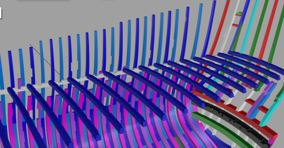
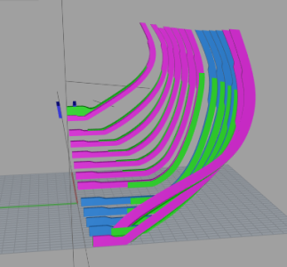
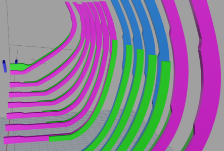
Today’s update covers the riders.You can see the upper edges of the riders are unfinished. After drawing them, I found interference with the deck beams. Some discrepancies are around 0.2–0.3 mm.
This means all deck beams need repositioning and redrawing. It is quite a setback for me.Still, I will keep working on the project. There may be no updates for about a week, ten days or longer, as I focus on redrawing the first to third gun decks.

1.png

2.png

3.png

4.png

5.png
 
Great question! For ships of this era, all frames are built perpendicular to the keel as the primary reference. The 2–3 foot difference between fore and aft displacement creates hull trim, so the frames are naturally not square to the waterline. That is how the original lines plan defines the framing.
Greetings Marc and Trident Model.

Your question, Marc, was about ships of this era, and that is the question answered by Trident Model (I apologize for not knowing your proper name). Of course I cannot speak to the overall construction of period ships - that is not my area of expertise.

But I can speak to the monograph and line drawings rendered by Mr. Lemineur. He clearly shows the frames are not perpendicular to the keel. By measurement I have them tipping forward 1.2 - 1.3 degrees. This is a matter of much debate on the French forum and many questions are raised there about this design choice. That tipping is reflected in every subsequent drawing and can even be seen when the drawings are “looking from above”.

Mr. Padoan does not speak to this subject (at least nowhere I have seen) so I cannot say if he is building to the plans or not.

I suspect I will be sorry to have posted this. I generally try to avoid embarrassing myself - the fact that I am not a naval architect is evident in my personal build reports. But I wanted to at least raise the issue with regard to the St. Philippe monograph.

Cheers.
 
Last edited:
Great question! For ships of this era, all frames are built perpendicular to the keel as the primary reference. The 2–3 foot difference between fore and aft displacement creates hull trim, so the frames are naturally not square to the waterline. That is how the original lines plan defines the framing.
It is quite a relief to hear that, as it simplifies construction. Thank you!
 
Greetings Marc and Trident Model.

Your question, Marc, was about ships of this era, and that is the question answered by Trident Model (I apologize for not knowing your proper name). Of course I cannot speak to the overall construction of period ships - that is not my area of expertise.

But I can speak to the monograph and line drawings rendered by Mr. Lemineur. He clearly shows the frames are not perpendicular to the keel. By measurement I have them tipping forward 1.2 - 1.3 degrees. This is a matter of much debate on the French forum and many questions are raised there about this design choice. That tipping is reflected in every subsequent drawing and can even be seen when the drawings are “looking from above”.

Mr. Padoan does not speak to this subject (at least nowhere I have seen) so I cannot say if he is building to the plans or not.

I suspect I will be sorry to have posted this. I generally try to avoid embarrassing myself - the fact that I am not a naval architect is evident in my personal build reports. But I wanted to at least raise the issue with regard to the St. Philippe monograph.

Cheers.
Hi Paul,
Thank you for raising this — this is exactly the kind of detail I need to hear.
You are right, and my earlier answer was too general. What I meant was that the frames are laid out from the keel as the reference, rather than from the waterline. But you are correct that in Lemineur's St. Philippe monograph the frames are not perfectly square to the keel — measuring the offsets does show a slight forward rake, around 1.2–1.3°, and it does show up in the plan view as well.
I will keep this in mind when I continue working on the framing in Rhino. Thanks again for the correction — very much appreciated.
Cheers,
Trident
 
Greetings Marc and Trident Model.

Your question, Marc, was about ships of this era, and that is the question answered by Trident Model (I apologize for not knowing your proper name). Of course I cannot speak to the overall construction of period ships - that is not my area of expertise.

But I can speak to the monograph and line drawings rendered by Mr. Lemineur. He clearly shows the frames are not perpendicular to the keel. By measurement I have them tipping forward 1.2 - 1.3 degrees. This is a matter of much debate on the French forum and many questions are raised there about this design choice. That tipping is reflected in every subsequent drawing and can even be seen when the drawings are “looking from above”.

Mr. Padoan does not speak to this subject (at least nowhere I have seen) so I cannot say if he is building to the plans or not.

I suspect I will be sorry to have posted this. I generally try to avoid embarrassing myself - the fact that I am not a naval architect is evident in my personal build reports. But I wanted to at least raise the issue with regard to the St. Philippe monograph.

Cheers.
Well, what’s interesting, Paul, is that I think I remember Nigel grappling with this issue quite a long time ago. I must confess that I have not dug up the SP monograph from where I keep it, but I trust what you are saying about the drawings is true.

However, from a practical standpoint, on the slipway, it would seem remarkably difficult to maintain a uniform forward cant. As far as I understand it, if what the shipwrights at Gravelines are doing with the Jean Bart reconstruction is credible (https://espacetourville.com/actus/tourville-actualite-n11-avril-2026/), the frames are raised in futtocks from the floors, on up.

The stem, sternpost and fashion pieces are erected first, and the hull rises from the floors. That said, there is additional confusion in models I have seen that purport to demonstrate shipyard practice. In this scenario, you have stem/stern/fashion pieces erected, as well as the full mid-ship flat frames, and the two full quarter frames, for and aft. Upon this minimal skeleton, ribands are attached to show the fair run of the hull. Any necessary adjustments can be made, before filling-in the fore and aft runs of frames.

Even in this scenario, I would think that in the 17th C., builders would have quite a challenging time avoiding cumulative error in their forward cant, unless the dead-flat section of framing is a sufficiently solid enough reference to extend the cant fore and aft.

As quite a number of the First Marine French builders (1660’s through 1680’s) were Dutch trained, it seems more likely that their ships rose from the keel.

 
Last edited:
Back
Top