I definitely like your work! I'm following your updates!
-

Win a Free Custom Engraved Brass Coin!!!
As a way to introduce our brass coins to the community, we will raffle off a free coin during the month of August. Follow link ABOVE for instructions for entering.
You are using an out of date browser. It may not display this or other websites correctly.
You should upgrade or use an alternative browser.
You should upgrade or use an alternative browser.
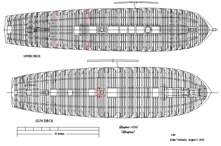
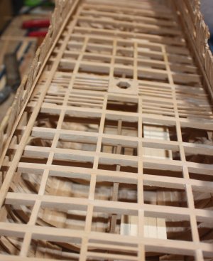
The gun deck beams were straight forward as were the carlings. Beams from 1650 to 1725 were made of single pieces of timber as the shortage of mature timber had not taken hold in England. Scores in the deck clamps were sometimes used and, according to Peter Goodwin, would have been 1 inch (less than half a mm at 1:64) But, in this case, the contract states that the beams were "tayled" rather than the clamps scored. I have not found any dates for when beam arms came into common use. There is a model of a 60 gun ship made in 1705 and a model from 1650 of a 56 gun ship at Preble Hall that do not have beam arms so I went with that and did not include them. If I got it wrong at least I know the masters made the same mistake.  The scantlings of the beams were taken from the contract.
NB: As can be seen in the photo, the tops of the top timbers appear to be quite thin, but they are right at scale. There are a lot of models in which the top timbers being far too thick resulting in having cap rails that are absurdly broad. From the contract: Top Timbers to be Three Inches in and out aloft.
NB: As can be seen in the photo, the tops of the top timbers appear to be quite thin, but they are right at scale. There are a lot of models in which the top timbers being far too thick resulting in having cap rails that are absurdly broad. From the contract: Top Timbers to be Three Inches in and out aloft.


I just went and measured the width of my top timbers. I always felt like I had over-faired the frames. Corrected for scale = about 3 inches! The KF is a smaller ship, but I still feel comforted.As can be seen in the photo, the tops of the top timbers appear to be quite thin, but they are right at scale.
- Joined
- Oct 17, 2020
- Messages
- 1,677
- Points
- 488

Hi AllanKP69 , Kudos for the documentation work and with a very nice set up of the details, I wonder: the bilge snakes are not there ( hull seepage water collection) ? Are the dimensions of the parts extracted from some table ? Thanks for Your feedback.FrankFraming can be as maddening at times but since I have gone to using a home made building board with a gantry it is much easier to get things right. The design for my set up is thanks to builder, author and friend Ed Tosti (HMS Naiad and Young America books) A good set of squares are not expensive and very useful at various parts of the build. I print out a framing guide and secure it to the building board with white glue as it is easy to moisten and remove once the hull is framed. In addition to making sure things are squared up the guide prevents cumulative error. A small error in location on one frame is easy to compensate for knowing where the frame line is to be, but it can accumulate drastically over 100 frames, so the guide is extremely useful in preventing this from happening.
Temporary pieces of wood are temporary glued to the top timbers to be sure frame does not spread or get squeezed during the framing erection process.
View attachment 480227
View attachment 480228
Alternating frames did not touch the keel until about 1710. (The Construction and Fitting of the English Man of War, page 14) As this would not be seen once the model is planked and decked I decided to add a chock to these partial frames. The drawing of two adjacent frames below shows the full frame and half frames. When half frames were to be used, all of the full frames are first erected then the half frames installed within 20 inches of the keel and secured with chocks and bolts to the full frames.
View attachment 480236
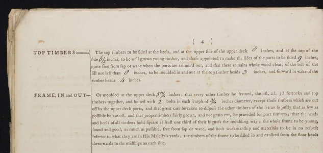
From the contract
Floor Timbers To be Thirteen Inches Fore and aft and Fourteen Inches up & Downe Upon ye Keele And of Such Lengths in the Floor of the Ships that their Heads May Lye Eighteen Inches at least above the Bearing thereof by a Streight line from the Bottome of the Keele and to be Eleven Inches (Moulded) in and out at the Wrongheads and Ten Inches Wrought in the Length of the Floor and before and abaft the Same to be Nine Inches Wrought in and out and Every Other Floor Timber To be Bolted Through the Keele with one Bolt by an Inch and Eighth auger.
Lower Futtocks To fill the Roomes Full and Workmanlike for the Strength of the Frame below And to be Twelve Foot long at least & to be Chocked Downe Within Twenty Inches of the Keele.
Upper Futtock Head to take the Lower Cill of the Ports in the Midships and the Heele of the Top Timber The Lower Edge of the Gundeck Clamps Within Board and Wale Without Board. To be Ten Inches fore and aft and Eight Inches in and out at the Breadth and to Stand an Inch and halfe Apart for Aire.
Top Timbers to be Three Inches in and out aloft. And the Whole Frame to be well Chocked with good Sound Timber.
Hi Frank,the bilge snakes are not there ( hull seepage water collection) ?
Sorry but I am not sure to what you are referring as bilge snakes is a new term for me. There is a shallow notch in the frames on which the pump suction end sits as seen in the photos in post #15 above. Could you please post a drawing that shows the bilge snakes as I am really curious about this. Sometime in the past I recall seeing modern drawings showing a notch in the frames but I have never found a contemporary drawing or text describing this on English ships. The first sketch below is mine and what I am imaging might be bilge snakes (the notches next to the keel) and the second is a contemporary frame drawing at RMG that does not show these notches.
Thanks
Allan
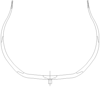
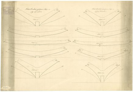
Perhaps, and I'm guessing here, Frank (@Frank48) has limber channels in mind?Hi Frank,
Sorry but I am not sure to what you are referring as bilge snakes is a new term for me. There is a shallow notch in the frames on which the pump suction end sits as seen in the photos in post #15 above. Could you please post a drawing that shows the bilge snakes as I am really curious about this. Sometime in the past I recall seeing modern drawings showing a notch in the frames but I have never found a contemporary drawing or text describing this on English ships. The first sketch below is mine and what I am imaging might be bilge snakes (the notches next to the keel) and the second is a contemporary frame drawing at RMG that does not show these notches.
Thanks
Allan
View attachment 485732
View attachment 485733
- Joined
- Oct 17, 2020
- Messages
- 1,677
- Points
- 488

Hi AllanKP69 , forgive me that with translators you don't always have a right question, I attach a few pictures that are worth more than a hundred words.FrankHi Frank,
Sorry but I am not sure to what you are referring as bilge snakes is a new term for me. There is a shallow notch in the frames on which the pump suction end sits as seen in the photos in post #15 above. Could you please post a drawing that shows the bilge snakes as I am really curious about this. Sometime in the past I recall seeing modern drawings showing a notch in the frames but I have never found a contemporary drawing or text describing this on English ships. The first sketch below is mine and what I am imaging might be bilge snakes (the notches next to the keel) and the second is a contemporary frame drawing at RMG that does not show these notches.
Thanks
Allan
View attachment 485732
View attachment 485733
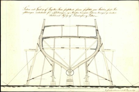
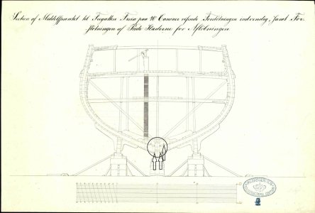
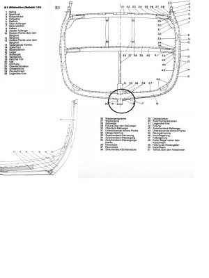
Bitts and cross pieces as well as the foremast partners can be seen below. Nothing special, just went with the original drawings and scantlings.
Bitt Pins Knees and Crosspeices To place Two Pair of Substantiall Bitt Pinns The Aftermost Pair To be Sixteen Inches and the Foremost pair to be Fifteen Inches Square in ye Head with Cross Pieces to Each pair of the Same Dimentions. To Step them in Hold and to place them abaft the Beame. To be Stopped with a score of an Inch Deep into the same and Bolted with Two Bolts in Each of an Inch Auger. To score ye Crosspeices into ye Bitts about Two Inches and to brace them together with Four pair of substantiall Iron Hookes and Eyes. To fix Two Pairs of good Standarts Upon Four Substantiall Carlings Placed between Beame and Beame in the Wake of them. The Fore and Aft Arme to be as long as the Bill Pinns are in Distance and Bolt them with Five Bolts in Each Standart by an Inch and Eighth Auger.
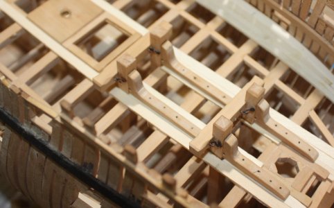
Bitt Pins Knees and Crosspeices To place Two Pair of Substantiall Bitt Pinns The Aftermost Pair To be Sixteen Inches and the Foremost pair to be Fifteen Inches Square in ye Head with Cross Pieces to Each pair of the Same Dimentions. To Step them in Hold and to place them abaft the Beame. To be Stopped with a score of an Inch Deep into the same and Bolted with Two Bolts in Each of an Inch Auger. To score ye Crosspeices into ye Bitts about Two Inches and to brace them together with Four pair of substantiall Iron Hookes and Eyes. To fix Two Pairs of good Standarts Upon Four Substantiall Carlings Placed between Beame and Beame in the Wake of them. The Fore and Aft Arme to be as long as the Bill Pinns are in Distance and Bolt them with Five Bolts in Each Standart by an Inch and Eighth Auger.


The furniture such as capstans, stoves, and pumps are fun projects in themselves and I find they are great to take a break away from the main hull.
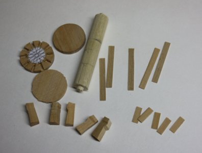
The capstans for this era are slightly different than the 18th century but there are a lot of drawings available in books by Lavery et al. The first pics are how I go about making a capstan. These were for another ship, but the last photo is the finished capstan for Litchfield.
Parts
Assembly of rough parts for upper capstan
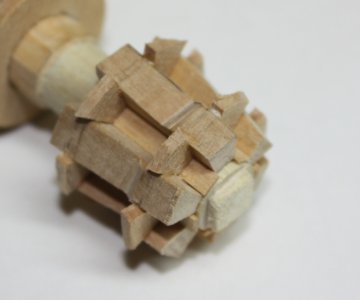
Nearly Finished lower capstan
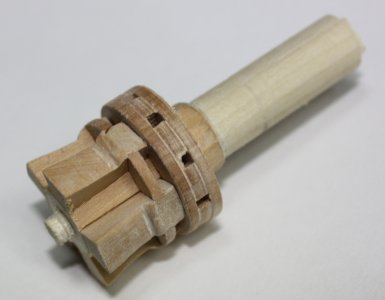
Finished Litchfield capstan. There is a third capstan aft as well.
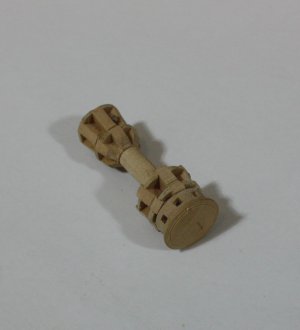
The capstans for this era are slightly different than the 18th century but there are a lot of drawings available in books by Lavery et al. The first pics are how I go about making a capstan. These were for another ship, but the last photo is the finished capstan for Litchfield.
Parts

Assembly of rough parts for upper capstan

Nearly Finished lower capstan

Finished Litchfield capstan. There is a third capstan aft as well.

Last edited:
I like this approach. Overbuild the chocks and sand back...The furniture such as capstans, stoves, and pumps are fun projects in themselves and I find they are great to take a break away from the main hull.
the capstans for this era is slightly different than the 18th century but there are a lot of drawings available in books by Lavery et al. The first pics are how I go about making a capstan. These were for another ship, but the last photo is the finished capstan for Litchfield.
Parts
View attachment 488495
Assembly of rough parts for upper capstan
View attachment 488496
Nearly Finished lower capstan
View attachment 488510
Finished Litchfield capstan. There is a third capstan aft as well.
View attachment 488513
I tried to be too clever and spent in inordinate amount of time trying to handle tiny bits with an average result. I also like how you veneered the cheap-wood spindle. Clever.
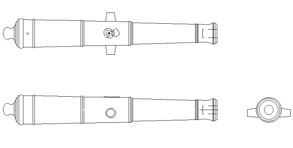
One of the good things about making cannon is that it can be done at any time. I took care to try to use the right barrel pattern and carriage pattern for English ships in 1695. The carriages were bracket and bed type until the introduction of the Borgard pattern gun carriages about 1716. The following carriage drawing is based on a carriage from the HMS London wreck which in turn was the basis of the drawings by Richard Endsor in The Master Shipwright's Secrets.
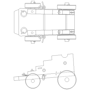
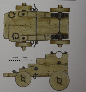
The barrels were Commonwealth pattern guns and I could not find any after market source so had to make my own or have them made. It was less expensive (US$0.80 each including freight) to have them made for me and they were much better quality, even as small as 1:64. Note the truncated cone shape of the trunnions. I sent the 3D drawings to the printer and had them in less than two weeks.
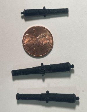
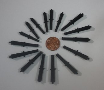
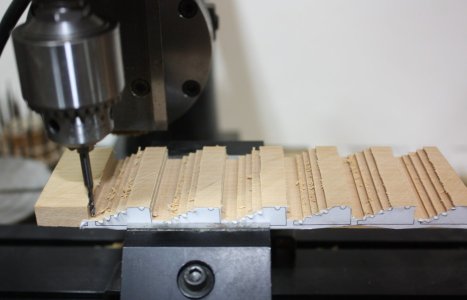
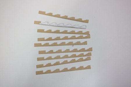
I used to make the carriages by cutting strips the same thickness as the dimension of the bore diameter, but luckily invested in a mill a couple years ago and made them with the mill and my old mini table saw. I printed the outline of the brackets on label paper and attached to a block of wood. I then milled the steps and once done, cut strips with the table saw. The trucks and brackets are the same thickness as the bore diameter. I have also used my mini drill press as a mill in years past but the bearings are not meant for lateral cutting and now show signs of wear.
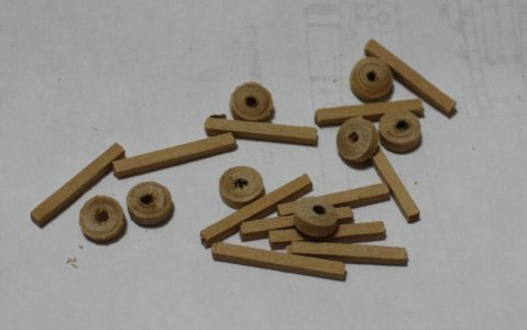
The trucks will be a matter of turning to the right diameter, drilling the right size hole for the axles and then slicing off individual units.
Allan


The barrels were Commonwealth pattern guns and I could not find any after market source so had to make my own or have them made. It was less expensive (US$0.80 each including freight) to have them made for me and they were much better quality, even as small as 1:64. Note the truncated cone shape of the trunnions. I sent the 3D drawings to the printer and had them in less than two weeks.


I used to make the carriages by cutting strips the same thickness as the dimension of the bore diameter, but luckily invested in a mill a couple years ago and made them with the mill and my old mini table saw. I printed the outline of the brackets on label paper and attached to a block of wood. I then milled the steps and once done, cut strips with the table saw. The trucks and brackets are the same thickness as the bore diameter. I have also used my mini drill press as a mill in years past but the bearings are not meant for lateral cutting and now show signs of wear.
The trucks will be a matter of turning to the right diameter, drilling the right size hole for the axles and then slicing off individual units.


Allan
Last edited:
Good morning Allan. Beautiful work on your HMS Litchfield. I learn so much from your posts and build log- thanks for sharing. Cheers Grant
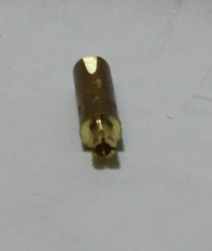
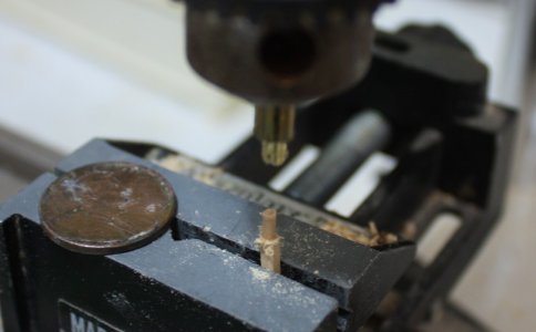
Little update. I made a new axle cutter as the ones I made in the past were for larger scale and larger guns. I have the good fortune to have a lathe so I can custom size everything, but these cutters can be made using brass tubing for anyone that does not have a lathe.
Rough axles and trucks
Axle Cutter
Cutting axle ends
Rough axles and trucks

Axle Cutter

Cutting axle ends

Hello Allan,
Your work has been a great tutorial for me. I have learned so much from your work and I am enjoying your build very much.
Bill
Your work has been a great tutorial for me. I have learned so much from your work and I am enjoying your build very much.
Bill
- Joined
- Dec 3, 2022
- Messages
- 1,475
- Points
- 443

It's interesting and informative to see your immense store of knowledge of our subject flowing out through your fingers, Allan. Litchfield looks very good.
(I know the town of Litchfield, it's quite near to my home.)
(I know the town of Litchfield, it's quite near to my home.)
THANK YOU Smithy. I just happen to be one of those people that loves research, and in my case, I write it down or download it because I will never remember 2% of the crazy stuff I find. It amazes me how the experts such as authors and curators in the arena of old ships have gone out of their way to help me over the years and I get it now as I find it a joy to share with others in return.
Allan
Allan


