• Win a Free Custom Engraved Brass Coin!!!
    As a way to introduce our brass coins to the community, we will raffle off a free coin during the month of August. Follow link ABOVE for instructions for entering.

Building a Pinnace

Joined
May 9, 2024
Messages
3,210
Points
588

The cutter project is done and the model in it's new home. Now I have a request for a pinnace and hope it will be interesting to anyone following this build.
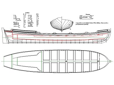
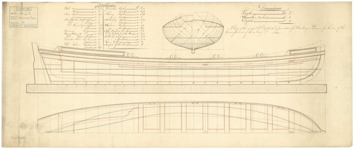
I chose a pinnace from 1800 as the drawing is quite detailed and the scantlings were all on the drawing as well as a note which are all shown on the copy of the drawing I made. The contemporary plans from RMG that I downloaded are from the Wiki Commons site. First up was downloading it and tracing the profile and top view.
Below is the original and the redrawn version. If anyone is interested I would be happy to scale the redrawn plans to whatever is needed and send out to you. I enlarged the original plan to 1:1 for the initial tracing. For my purposes I then reduced to 1:48 which will yield a 7.5" boat (if I build it accurately :) ) If any mistakes are found, or questions arise please feel free to point them out.
Allan
1755344019211.png

1755344599624.jpeg
 
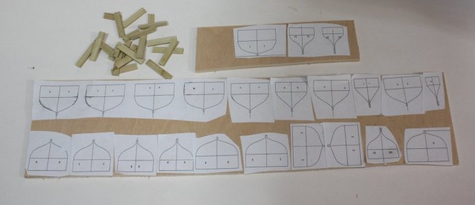
I traced the station lines which are to the outside of the frames. I then reduced them 1.5 inches (full scale) to accommodate the thickness of the frames that will go over the formers. They were then printed on label paper and stuck to plywood. My garage is hot in the summer and sweat dripped off my brow and the ink ran in a couple spots so a new printout is needed, but not a big deal, just a sheet of paper.

The photo shows each former piece on the plywood which is 0.218" thick. With the room and space being 15" (0.3125", 7.9375mm) I like to use spacers to stiffen the assembly of formers. The spacers are 0.094" thick. Believe it or not, the glue will have a thickness to it that can throw things off so when these are assembled on the build board, a continual check needs to be made to avoid cumulative error. Even 0.005" too thick over 20 spaces would accumulate to the boat being about 5" (127mm) too long at full scale, 2.65mm at 1:48

The photo below shows the spacers top left and the plywood with the formers.

Allan

1755525497246.jpeg
 
Golf course is closed this week for our last punch of the year so more time for the pinnace project. :)

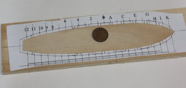
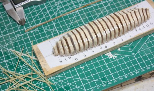
The build board is just a piece of 1/2" plywood scrap cut to meet my needs. The plan view drawing was printed on label paper and put onto the build board. I then drilled holes to accommodate the tops of the frames and hold them in place during the bending and then the planking process. The center portion was then cut out so the formers can be glued wood to wood. Gluing to the label paper does not work for obvious reasons. It's as bad or worse than gluing to a painted surface instead of wood.

Allan

1755530272673.jpeg
 
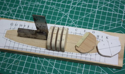
Progress on building the forming unit. Note that I cut off the corners so I have room to get a snipper to cut off the frames a little above the board so I can remove the little pieces left in the holes later on and save the forming set up for future builds. I'll try to remember to post a photo of this when this is done for a clearer explanation.
Allan
1755603984712.jpeg
 
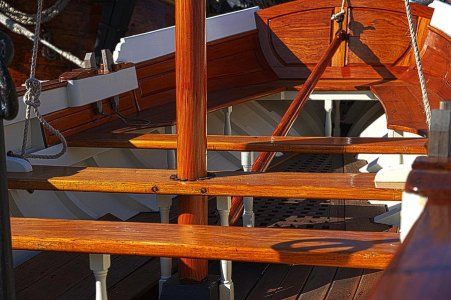
Allan, congratulations on a good start! The replica of the Endeavour's pinnace is very well done. Allan, look for photos on the Internet (I don't have any). Many details omitted from the drawings are visible and understandable there.
endeavours-pinnace-miroslava-jurcik.jpg
 
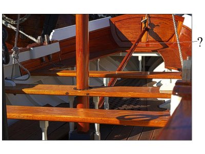
Thanks Iutar, your post and photo are very much appreciated. What is the item marked below? I thought maybe a tiller or sail boom but not sure as it looks to be attached to the mast under the thwart.

I see pillars under the thwarts and benches. I have not seen these on any contemporary drawings of a 30 foot English pinnace or models. Do you have any information about these based on contemporary sources? I would like to know more about these.

THANKS AGAIN
Allan

1755613986717.jpeg
 
This is the gaff. It's been removed and is just lying to the side of the mast.
I have not been able to find any systematic information on stanchions. There are stanchions, then there are none. Considering the large number of people transported by this boat (there is even a longitudinal seat), I think stanchions should be installed.
 
Considering the large number of people transported by this boat (there is even a longitudinal seat), I think stanchions should be installed.
You may be right. All things considered, the breadth is only 6 foot 4 inches and single banked so typically only one person per thwart. There are fixed thwarts which I think should have a pillar. For the thwart at station "A" there would need to be one on each side of the mast opening. It could be that one would suffice if off center, but it would not look right in my mind.

Thanks for your input Iutar, always appreciated, and a pleasure to see parts of your library of photos.

Allan
 
The "plug" is finished on the building board. Based on the scantlings in the original drawing the frames are sided and moulded 1.25" (0.026"/0.66mm at 1:48). They are pliable enough to bend after only five or ten minutes in water. It is hard to see in the photo, but three frames are in place and rest are laying on the left side of the plug ready to go into a cup of water. The white pieces are cardstock about half the thickness of the frames. They help keep the frames centered on the forming plug and thin enough not to get glued to the planks when they go on.
Allan
1755694233442.jpeg
 
Back
Top