• Win a Free Custom Engraved Brass Coin!!!
    As a way to introduce our brass coins to the community, we will raffle off a free coin during the month of August. Follow link ABOVE for instructions for entering.

O.B. Bolton Marine Triple Expansion Steam Engine using castings by AJ Reeves, drawings by John Bertinat

Bolton part eighteen

When I was reading the DRO manual for my mill, I thought I would use the pitch circle diameter function to drill my cylinder covers/block. Seems that whilst I have the buttons for these additional functions, they are not included on my particular model:(

A bit like when you bought a base model car and there were blanking plugs where electric window switches would be, yes I am going back a few years now:rolleyes:

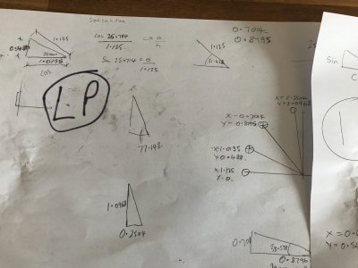
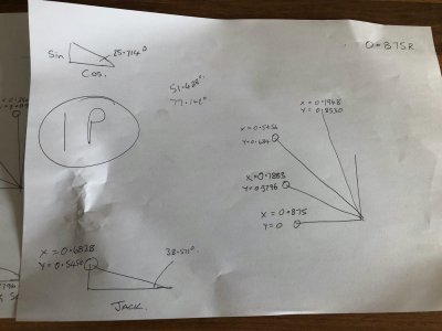
So back to school it felt like for me, I include pictures of my "spider scrawl" just to illustrate Pythagoras had a lot to do with my hole drillingROTF

Using the centre of each bore as my datum I calculated x and y coordinates for my holes. At least I only had to do calculations for one quarter as the rest are mirror images. I could have set the covers up on my rotary table but 14 divisions does not easily divide up 360 degrees, so I knew I would end up with some sort of cumulative error, plus I would still have to drill the block.

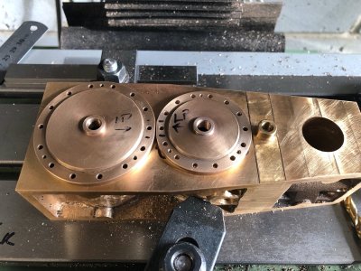
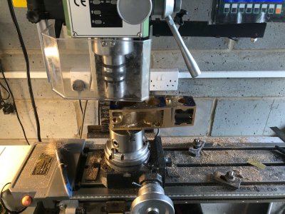
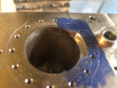
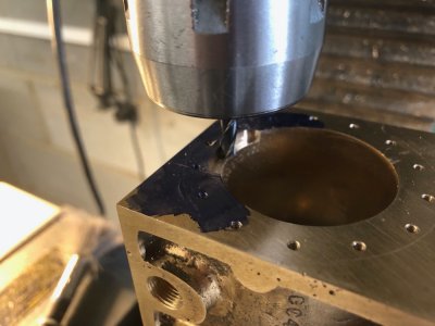
I referenced the inside of one bore at a time using my edge finder and fitted the respective cover with some dabs of medium CA on the flange.

My holes were then drilled tapping size through cover and block to the required depth. The holes were opened up to clearance size in the cover alone using the depth gauge on the quill. The CA was then broken by warming the cover with a blowlamp and the cover removed. The holes in the block were then tapped 7BA.

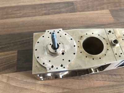
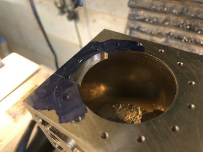
It was tapping the holes for the IP cylinder that disaster/ inevitable happened. My tap broke. Fortunately it snapped just above the hole and on the way out so I carefully managed to unscrew the remaining piece of tap. The tap had done a number of holes and 7BA is only 2.5mm diameter ! I have no doubt I will break some more in the process of tapping the myriad of 7BA holes on this engine.

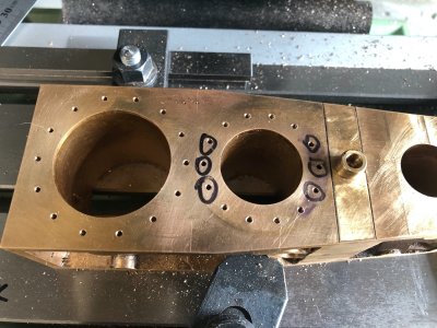
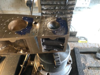
So this stopped play. Another tap has been ordered and the holes with the black circles around them are just a reminder these are still to tap.

One detail I have added is three " jacking" screws to each cover. On the real engine these are just threaded through the cover and tightening these allowed the mechanic to pop the seal in the gasket. These have been tapped slightly smaller at 8BA which is around 2mm diameter. I will have the challenge later of machining some square head bolts for these holes.
IMG_2950.jpgIMG_2951.jpgIMG_2952.jpgIMG_2953.jpg
 
This is one area that even the most basic CAD will shine. You can do circular patterns and then measure their location. Though remembering your old sohcahtoa calculations is impressive in and of itself.
 
If you had to order one tap, I hope you ordered a small handful. I agree with you that at that size they are prone to quitting.
 
If you had to order one tap, I hope you ordered a small handful. I agree with you that at that size they are prone to quitting.

Only ordered one as I had to order some other supplies and that stockist only does sets of three, 1st 2nd and plug. They are only high carbon steel, I intend to find some high speed steel ones but rather not buy sets just plug taps as most holes on this engine are blind tapped and hss taps are more expensive
 
Bolton part nineteen

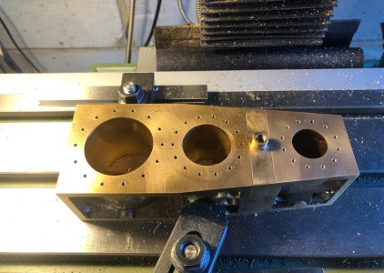
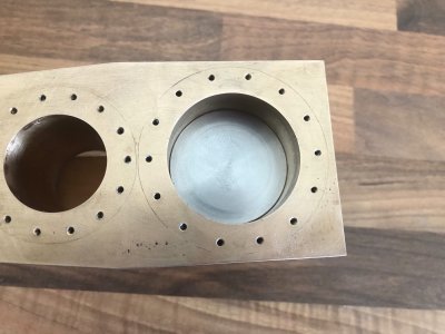
With the broken tap replaced, I was able to complete the drilling of the covers and tapping of the block for all three cylinders

IMG_2957.jpg

The last job on the covers before painting them was to add the Fracture grooves. As I mentioned earlier, these are present on the prototype incase of over pressurising in a cylinder. They are to encourage the Cylinder cap to breakup rather than damage the block.
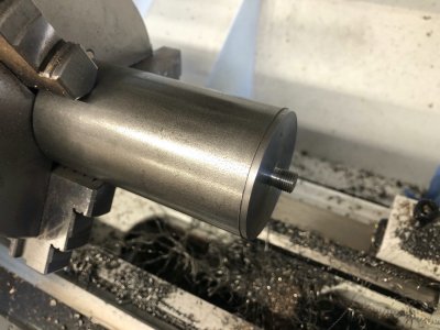
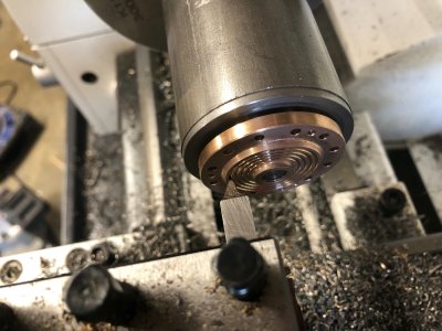
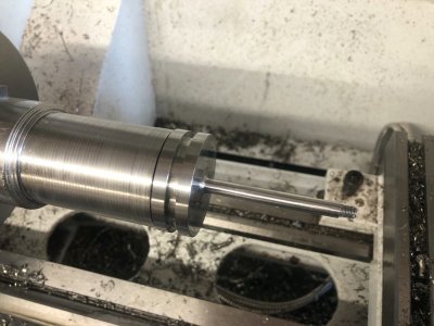
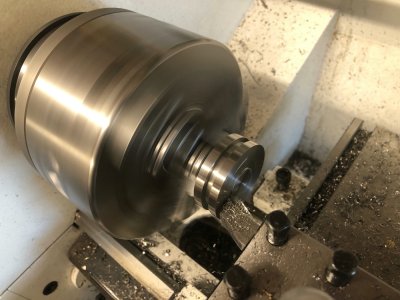
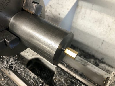
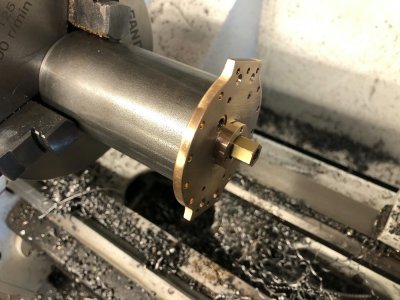
To turn these on the caps, I first made a mandrel from stock steel bar. This ensures the caps are concentric and also perpendicular to the cylinders centreline.The Mandrel had a thread added to allow the cap to screw on using the thread for the pressure relief valve.The rotation of the lathe means tool force will tighten, not undo the thread so no additional fixing is needed.

IMG_2956.jpg

The grouves were then turned in each cap using a modified/reground threading tool.

IMG_2955.jpg

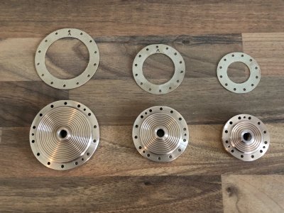
Final job was to use the covers as templates to make the relevant gaskets out of 1/64" gasket material.

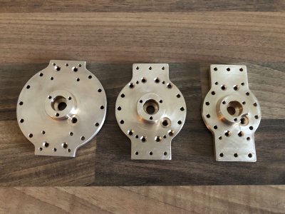
The completed covers ready for paint and their respective gaskets. The little arrow indicates the small flat I added for paint clearance between the two larger covers.
IMG_2958.jpg
 
Bolton part twenty

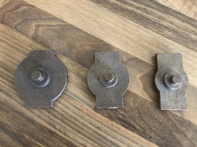
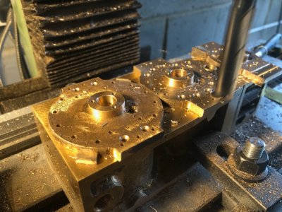
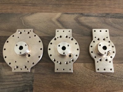
I machined the lower covers in a similar way to the top except I did not finish the underside face on the lathe. Once the covers had been match drilled along with the block, the bottom face of all three covers were milled at the same time whilst affixed to the block to ensure they all formed a true flat face that sits on top of the columns. I also carefully trimmed the ears to size that line up with the column tops. The curved edges will be dealt with latter on the rotary table. The covers will have to go on a purpose made mandrel to finish of the central area.

IMG_2959.jpgIMG_2965.jpgIMG_2966.jpg

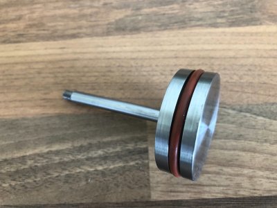
I have also started on the pistons. These are turned from 303 Stainless steel. I have elected to make them in one piece with the rod. I have also decided to use steam grade silicon O rings for the seal rather than two pice pistons with hard brass homemade rings.

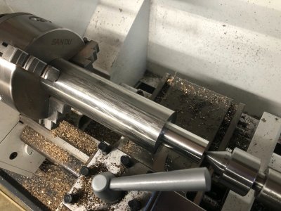
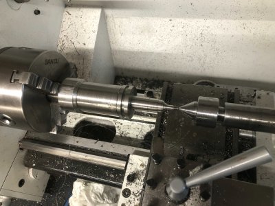
I have started with the largest of the three, the Low Pressure piston which started life as 2" round stock. Turning the end down to 1" first to get better engagement in my chuck which has insufficient bore to take 2" internally.
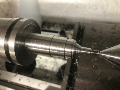
The small thread on the end of the rod will screw into the crosshead. I have three blind holes to drill into the piston crown which will take a homemade tool to allow the piston/rod to be screwed in and also removed for maintenance.

IMG_2961.jpgIMG_2963.jpgIMG_2964.jpgIMG_2967.jpgIMG_2968.jpgIMG_2969.jpgIMG_2970.jpgIMG_2971.jpg
 
In my limited experience with 303 stainless and monel threaded nuts and bolts, which is used around a saltwater environment, if you let one little spec of grit or tiny sliver of metal get in between the threads it welds itself to the nut or insert you may be using. We had to use a silver looking grease called never seize prior to placing nut and bolt together.
 
In my limited experience with 303 stainless and monel threaded nuts and bolts, which is used around a saltwater environment, if you let one little spec of grit or tiny sliver of metal get in between the threads it welds itself to the nut or insert you may be using. We had to use a silver looking grease called never seize prior to placing nut and bolt together.

A very interesting point Daniel. Grade 303 isn't normally recommended for a marine (saltwater) application with 316 being the preferred grade for that environment. The crosshead will also be made from 303 but I will be using a thread lock between the two. Piston coming undone whilst running will result in collision with the cylinder top cap.

I plan to machine as many components as possible from 303 however all the fixings will be mild steel, with a couple of exceptions.Yes I run the risk of contamination should rusting occur but I am not planning on that happening, all bright areas will be covered with a thin film of WD40 or an alternative inhibitor whilst on display.
 
Bolton Part twenty one

I turned a threaded mandrel from some stock mild steel round bar and all a special nut to clamp the lower covers inside the gland recess.

This enabled me to do the final finishing on the lathe of the central area around the boss. The lower cylinder covers were then tapped and countersunk where necessary. I neglected to take any WIP pictures, pics below show the completed covers after final hand finishing prior to paint

IMG_2976.jpgIMG_2977.jpgIMG_2978.jpg
 
Bolton part twenty two.

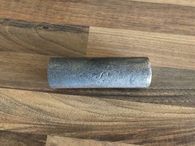
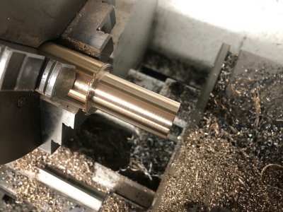
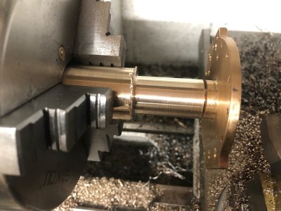
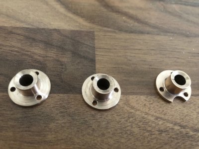
The next parts to produce were the three gland "nuts" for the piston rod glands. These compress Graphited Yarn around the Piston rods to form a steam proof seal. Although the drawing specifies Brass, I opted for continually cast Gunmetal as it is more resilient.This is bought by the inch and comes rough cast. It is unfortunately about 6 times the price of brass. The first picture illustrates the rough form it comes in. One further point, the single hole towards the middle of each cover is for the lower pressure relief valve.

IMG_2979.jpgIMG_2980.jpgIMG_2981.jpgIMG_2982.jpgIMG_2983.jpg

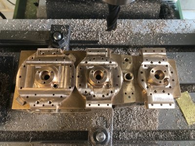
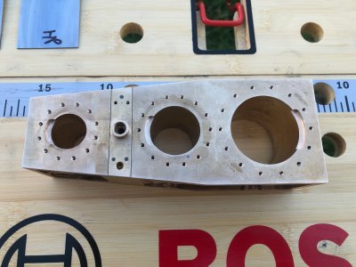
Next step is to mill the reliefs at the top and bottom of each cylinder. Diagonal holes will link these to the slots previously milled in the block faces. These will become the steam inlet passages. The holes will be drilled later once the block is separated into its component parts.

IMG_2984.jpgIMG_2986.jpgIMG_2987.jpg

IMG_2985.jpg
 
Bolton part twenty three

In order to machine the pockets in the high pressure cylinder, I turned down a steel peg that fitted snugly in the bore and was clamped in the chuck on the rotary table. Peg and block were held together temporarily with a blob of epoxy

IMG_2988.jpg

All the pockets have now been milled on the top and bottom of all three cylinders

IMG_2989.jpgIMG_2990.jpg

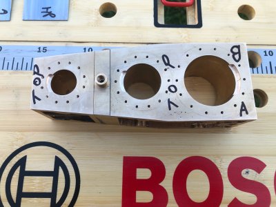
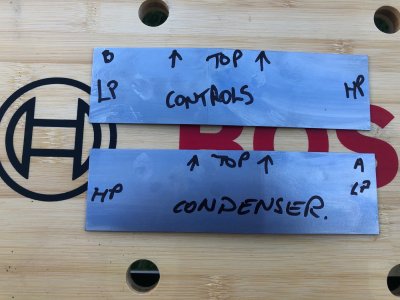
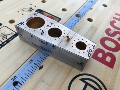
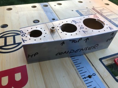
Before the block is split into it's constituent parts, I need to make and temporarily fit the block clading. This will be secured to the block with small bolts and mocking things up now will enable me to drill the cylinder drain cock holes through everything rather than trying to locate them in the cladding retrospectively.

The cladding was cut from 0.9mm mild steel sheet using an electric jigsaw and hand filled to size. The bend was also added to follow the shape of the block.
I intended to paint this cladding the same as the engine but I am now undecided if I am going to chemically blue it. A lot to do before that so plenty of time to ponder. The sun was out today so I set my folding workbench up in the garden to work on the cladding.

IMG_2991.jpgIMG_2992.jpgIMG_2993.jpg
 
Back
Top