


This is the story of a number of failures. At my age and with my track record nobody will call me a beginner, but that did not prevent me from making several beginner's mistakes, as recorded here. A few years ago I was planning to build a 160 foot VOC ‘retourschip’ (a ship designed for the Dutch Eastindia Company (VOC), constructed to make several journeys to and from Asia).
But things do not always turn out the way we plan….

Thirty years ago, around 1986, I reconstructed the lines of a 160-foot VOC ship. I used data, found in a book by P. van Dam: Beschreyvinge van de Oostindische Compagnie (Description of the Eastindia Company). He wrote the book in commission of the ‘Heeren XVII’ (the managing directors of the VOC) and published it in 1701. His system was to work his way through the so-called ‘Resoluties’, a sort of reports of the meetings they held twice a year, making important decisions for the Company. In April 1697 finally their specifications for the building of ships were so precise that I could make lines plans out of them.

A little bit of history (you can skip this if you don't like history):
Why did the VOC stipulate the instructions for their shipyards in so small detail? To understand that you have to know that the Netherlands were not really a country in the 17th century. The area existed of cities, ruling the surrounding territories, the provincies. In fact, their rich inhabitants ruled the country. In Holland people gradually freed themselves from the dominance of nobility and church in the years after the Middle Ages. The result was a small number of cities, which were most competitive towards each other. There was no such thing as patriotism or even the notion of any feeling of nationality. Every city looked after its own interests and sometimes they even fought each other.
To manage the country every province sent some of its prominent inhabitants, so-called ‘Staaten’, to The Hague, where they met in the ‘Staaten Generaal’, where important national matters like politics, war and peace were discussed and sometimes even decided.
The VOC was a sort like 'informal' organisation. To prevent rivalry between the cities in trading Asian products, the Staaten forced the cities to operate the trade together. There were six cities interested in the Asian trade, so representatives of each city would come together twice a year to make the necessary decisions on every aspect of the trade. For instance, the number and sizes of ships per city were established. Shipyards were strictly controlled to prevent them from secretly building too large ships, for that would cause an uneven distribution (and earning) of the spices.
The Resolutions of April 1697 were the first where the lines of the ships were stipulated into great detail. Nine frames were measured on six different locations, after which I managed to make the drawings at the kitchen table. (actually there were data for three ‘rates’: 160, 145 and 130 feet long and another one for ‘fluits of hagboats’ of 130 feet, and I worked them all out).

The data strictly followed the shipbuilding rules of those days, so the lines plans I made were not exactly like what we are used to nowadays, but at least they gave a precise impression of the shape of the ships involved.
In 2008 Rob Napier wrote a wonderful book about the restoration of a Dutch VOC model from 1717, the Valkenisse. In it he lists every model of VOC ships that survived the ages. There are about twenty. The oldest was the Prins Willem from 1651, nowadays exhibited in the Rijksmuseum in Amsterdam. Its lines have been taken off and worked out in drawings by my predecessor at the museum, Herman Ketting, who wrote a book about the model. For a long time his lines plan was regarded as old as authentical. However, slowly some doubts were felt about the correctness of the shape, because the model might have served other purposes than closely representing the lines of the actual vessel. It was on display in one of the VOC meeting rooms as a decoration piece. Besides of that, the model maker did not have a lines plan at his disposal to produce the shape of his model and it might just be possible that he never saw the ship out of the water. So the shape of the model could only be a fair image of how he thought it to be. The drawings from the 1697 Resoluties however are probably the first true depiction of the shape of a VOC ship, based on hard evidence.
Time to build a model…. I thought.
But as said, my lines plan was not very practical. So my late friend Cor Emke fed it to the computer and his Autocad program spit out a set of modern lines plans:

It was this set of plans I used for my model. Anyone who followed my previous thread about the Dutch man-of-war knows how the system works: a central spine with frames sled in, all made out of 1 mm thick cardboard. For the central part I used three layers, with additional strips to serve as rabbets for the planking. Not really very complicated and not too impressive either, except for the size on 1/77 scale: over 60 cm between stem and stern, almost one meter when rigged.


On a bad day I compared the model with my original 1986 drawing and doubts started to creep in. Where amongst others had the angled bilge gone, so prominently present in my drawing?
I stumbled back to the computer to compared my lines with the Autocad ones. It appeared that programs like Autocad (and Delftship too for that matter) change the lines they get and turn them into a nice smooth water-friendly shape. The bottom on the new plan was much flatter, the bilge wider, as were the sides of the ship. It had nothing to do with the shape dictated in the Resoluties. And I was stupid enough never to have compared the results with the original. That was my first beginner's mistake.

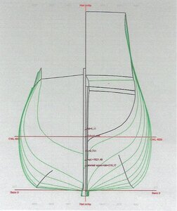
Then my Delftship expert Rene Hendrickx fed Van Dam's data to the Delftship program and did some massage to convince it to produce the unwieldy lines our forefathers gave to their ships. And comparing my old drawing with the Delftship results proved that working on the kitchen table did not do that badly:

That was nice to find out, but in the mean time here I was with a 60 centimetres long hull that did not represent the precious lines the Heeren XVII decided on. There was nothing else I could do than start anew. Here the good side of working with paper showed: in less than a week I had another hull.... I thought. But looking better at the newly produced second hull I could not help noticing that I forgot to check the squareness of the stem and stern in relation to each other. When I finally did check they deviated almost 10 degrees and there was nothing I could do to correct that. It was my second stupid beginner’s mistake, which was punished by kicking the hull into the dustbin. Here is a small pile of models: the first try with the round bilge, an 18th century East Indiaman of 150 feet (another project) and the second failure of the 160 one on top.

I waited a while and licked my wounds, but one day I started my third effort and this time I produced a flawless hull, complete with angled bilge and all.


It is not finished and I really don't know if I will ever will finish it. As I said, it's a large model and with four of five other big ones a house becomes crowded and the admiral will not be happy. But at least I can treasure the authentic shape of the vessel. It shows how the VOC chose for wide-bodied ships, to carry as much cargo as possible. Don't be fooled by all the gun ports. Twenty-seven per side. Did they really carry 54 guns? No, according to the Resoluties 38 was the maximum number. But showing the (possible) armament was a good way of fencing off pirates. Probably the lower gunports were only opened to allow some air into the crowded below-decks. All the rest of the space was used for cargo. But if necessary these ships could be armed as a fighting ship as well. Comparing this bulbous shape with the hull of a man-of-war of the same era I made last year (a reliable English one, because it was built after plans) shows a completely different concept: loading capacity towards speed.

And that first hull, the one with the round bilge, what happened to that one? Also in the dustbin? No, I could not help using that one for another man-of-war after some modifications of the above water part. Meet my 'Alkmaar':

Hope I did not bore you too much")
Ab
But things do not always turn out the way we plan….
Thirty years ago, around 1986, I reconstructed the lines of a 160-foot VOC ship. I used data, found in a book by P. van Dam: Beschreyvinge van de Oostindische Compagnie (Description of the Eastindia Company). He wrote the book in commission of the ‘Heeren XVII’ (the managing directors of the VOC) and published it in 1701. His system was to work his way through the so-called ‘Resoluties’, a sort of reports of the meetings they held twice a year, making important decisions for the Company. In April 1697 finally their specifications for the building of ships were so precise that I could make lines plans out of them.
A little bit of history (you can skip this if you don't like history):
Why did the VOC stipulate the instructions for their shipyards in so small detail? To understand that you have to know that the Netherlands were not really a country in the 17th century. The area existed of cities, ruling the surrounding territories, the provincies. In fact, their rich inhabitants ruled the country. In Holland people gradually freed themselves from the dominance of nobility and church in the years after the Middle Ages. The result was a small number of cities, which were most competitive towards each other. There was no such thing as patriotism or even the notion of any feeling of nationality. Every city looked after its own interests and sometimes they even fought each other.
To manage the country every province sent some of its prominent inhabitants, so-called ‘Staaten’, to The Hague, where they met in the ‘Staaten Generaal’, where important national matters like politics, war and peace were discussed and sometimes even decided.
The VOC was a sort like 'informal' organisation. To prevent rivalry between the cities in trading Asian products, the Staaten forced the cities to operate the trade together. There were six cities interested in the Asian trade, so representatives of each city would come together twice a year to make the necessary decisions on every aspect of the trade. For instance, the number and sizes of ships per city were established. Shipyards were strictly controlled to prevent them from secretly building too large ships, for that would cause an uneven distribution (and earning) of the spices.
The Resolutions of April 1697 were the first where the lines of the ships were stipulated into great detail. Nine frames were measured on six different locations, after which I managed to make the drawings at the kitchen table. (actually there were data for three ‘rates’: 160, 145 and 130 feet long and another one for ‘fluits of hagboats’ of 130 feet, and I worked them all out).
The data strictly followed the shipbuilding rules of those days, so the lines plans I made were not exactly like what we are used to nowadays, but at least they gave a precise impression of the shape of the ships involved.
In 2008 Rob Napier wrote a wonderful book about the restoration of a Dutch VOC model from 1717, the Valkenisse. In it he lists every model of VOC ships that survived the ages. There are about twenty. The oldest was the Prins Willem from 1651, nowadays exhibited in the Rijksmuseum in Amsterdam. Its lines have been taken off and worked out in drawings by my predecessor at the museum, Herman Ketting, who wrote a book about the model. For a long time his lines plan was regarded as old as authentical. However, slowly some doubts were felt about the correctness of the shape, because the model might have served other purposes than closely representing the lines of the actual vessel. It was on display in one of the VOC meeting rooms as a decoration piece. Besides of that, the model maker did not have a lines plan at his disposal to produce the shape of his model and it might just be possible that he never saw the ship out of the water. So the shape of the model could only be a fair image of how he thought it to be. The drawings from the 1697 Resoluties however are probably the first true depiction of the shape of a VOC ship, based on hard evidence.
Time to build a model…. I thought.
But as said, my lines plan was not very practical. So my late friend Cor Emke fed it to the computer and his Autocad program spit out a set of modern lines plans:
It was this set of plans I used for my model. Anyone who followed my previous thread about the Dutch man-of-war knows how the system works: a central spine with frames sled in, all made out of 1 mm thick cardboard. For the central part I used three layers, with additional strips to serve as rabbets for the planking. Not really very complicated and not too impressive either, except for the size on 1/77 scale: over 60 cm between stem and stern, almost one meter when rigged.
On a bad day I compared the model with my original 1986 drawing and doubts started to creep in. Where amongst others had the angled bilge gone, so prominently present in my drawing?
I stumbled back to the computer to compared my lines with the Autocad ones. It appeared that programs like Autocad (and Delftship too for that matter) change the lines they get and turn them into a nice smooth water-friendly shape. The bottom on the new plan was much flatter, the bilge wider, as were the sides of the ship. It had nothing to do with the shape dictated in the Resoluties. And I was stupid enough never to have compared the results with the original. That was my first beginner's mistake.
Then my Delftship expert Rene Hendrickx fed Van Dam's data to the Delftship program and did some massage to convince it to produce the unwieldy lines our forefathers gave to their ships. And comparing my old drawing with the Delftship results proved that working on the kitchen table did not do that badly:
That was nice to find out, but in the mean time here I was with a 60 centimetres long hull that did not represent the precious lines the Heeren XVII decided on. There was nothing else I could do than start anew. Here the good side of working with paper showed: in less than a week I had another hull.... I thought. But looking better at the newly produced second hull I could not help noticing that I forgot to check the squareness of the stem and stern in relation to each other. When I finally did check they deviated almost 10 degrees and there was nothing I could do to correct that. It was my second stupid beginner’s mistake, which was punished by kicking the hull into the dustbin. Here is a small pile of models: the first try with the round bilge, an 18th century East Indiaman of 150 feet (another project) and the second failure of the 160 one on top.
I waited a while and licked my wounds, but one day I started my third effort and this time I produced a flawless hull, complete with angled bilge and all.
It is not finished and I really don't know if I will ever will finish it. As I said, it's a large model and with four of five other big ones a house becomes crowded and the admiral will not be happy. But at least I can treasure the authentic shape of the vessel. It shows how the VOC chose for wide-bodied ships, to carry as much cargo as possible. Don't be fooled by all the gun ports. Twenty-seven per side. Did they really carry 54 guns? No, according to the Resoluties 38 was the maximum number. But showing the (possible) armament was a good way of fencing off pirates. Probably the lower gunports were only opened to allow some air into the crowded below-decks. All the rest of the space was used for cargo. But if necessary these ships could be armed as a fighting ship as well. Comparing this bulbous shape with the hull of a man-of-war of the same era I made last year (a reliable English one, because it was built after plans) shows a completely different concept: loading capacity towards speed.
And that first hull, the one with the round bilge, what happened to that one? Also in the dustbin? No, I could not help using that one for another man-of-war after some modifications of the above water part. Meet my 'Alkmaar':
Hope I did not bore you too much
Ab
Attachments
Last edited:

")


