A little help with a rigging drawing, please?

  • Thread starter Thread starter Stauf
  • Start date Start date
  • Watchers Watchers 6
Joined
Feb 11, 2024
Messages
5
Points
3

Ok, time for a beginners question. In the attached picture it shows a single rope going to a belaying pin. However, it’s indicating multiple belaying pins as a possible termination point. For example one of them says JT35-JT39, Does that mean I could use any pin within that range? Seems like each rope should have a designated belay pin, or are these “ranges” basically just a suggested location? Thanks guys!
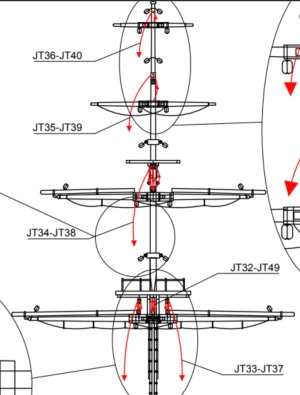
IMG_2692.jpeg
 
what does the belaying plan say? I am thinking that you have two separate points with one being a pulley and the other a belaying pin, or rail.
 
Last edited:
Jack,
What ship/nation/year is this drawing for? The rigging varied over time and individual ships did not all necessarily get rigged exactly the same way. J33-37 look like jeers for the fore yard and/or the main yard. They ran down to and through the inner sheaves in the jeer bitt pins and I am pretty sure they belayed to the bitt pins and cross piece rather than belaying pins. J32 looks like it might be a tie but if there were jeers there would be no tie needed. Ties ceased to be used by about 1660 on English ships on the lower yards and jeers came into use. The rigging of the jeers varied with time as well. If you could share what ship and year this is for, more details are available to help you. No matter what, rigging seems to be an inexact science and confuses most of us at one time or another. :(
Allan
 
Please show us the belaying plan (top view of the deck). It seems odd that one line would be designed for two beaying points, such as the ties for the topgallant and royal sail yards. If the tie runs down to a block through which a halyard runs, the two belaying points could be 1) the eyebolt where one end of the halyard is tied, and 2) the belaying pin where there other end of the tie is belayed. Which ship model is this?
 
Last edited:
I’m sorry, this is for the Occre HMS Beagle, I should’ve mentioned that earlier. This is my first build and haven’t had too many problems that I couldn’t work through. So now I have progressed to the point of starting the rigging and to be honest it’s a bit intimidating to me, hence the noob question.

IMG_2693.png
 
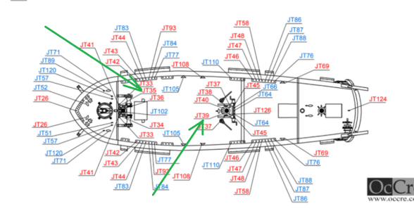
They are showing you one mast, but if you go to the deck belaying plan it shows one number line is for the main mast and the other number line is for the fore mast, hope this helps,

eg 37 and 33,

37 is going down the main mast to the deck and 33 is going down the fore mast to the deck,


best regards john,
Thanks John, I understand what you’re saying, I think that it could be layer out a little more straight forward,but if that’s the way they do it, then so be it. I’m sure I’ll have more questions as I go down the rabbit hole, but if I go slow and steady hopefully I won’t wind up with a mess on my hands. Thanks again!
 
I’m sorry, this is for the Occre HMS Beagle, I should’ve mentioned that earlier. This is my first build and haven’t had too many problems that I couldn’t work through. So now I have progressed to the point of starting the rigging and to be honest it’s a bit intimidating to me, hence the noob question.

View attachment 471468
On this belaying plan there are the belaying points of your running rigging clearly marked
Looking at your example

JT35 and JT39

IMG_2693.png
 
On this belaying plan there are the belaying points of your running rigging clearly marked
Looking at your example

JT35 and JT39

View attachment 471489

Uwek, thank you for your reply. I had seen the belaying pin locations. Where my confusion came in was the fact that the mast diagram was indicating two different locations for one rope. I wasn’t aware they were referring to two masts. I searched quite a bit for an answer to this, perhaps I missed something along the way?
 
Uwek, thank you for your reply. I had seen the belaying pin locations. Where my confusion came in was the fact that the mast diagram was indicating two different locations for one rope. I wasn’t aware they were referring to two masts. I searched quite a bit for an answer to this, perhaps I missed something along the way?
Good that this problem or open question is solved....... have fun
 
They are showing you one mast, but if you go to the deck belaying plan it shows one number line is for the main mast and the other number line is for the fore mast, hope this helps,

eg 37 and 33,

37 is going down the main mast to the deck and 33 is going down the fore mast to the deck,


best regards john,
Now it makes sense. One drawing for both masts.
Kit makers usually assume you have built a wooden ship model before and are familiar with what goes where. That's one of the problems you have to overcome building your first kit.
 
Ok, time for a beginners question. In the attached picture it shows a single rope going to a belaying pin. However, it’s indicating multiple belaying pins as a possible termination point. For example one of them says JT35-JT39, Does that mean I could use any pin within that range? Seems like each rope should have a designated belay pin, or are these “ranges” basically just a suggested location? Thanks guys!

View attachment 471443
Hi there this is simply indicating all the mast configuration take a look at your deck plan and you will see the various positions relative to the masts
 
Back
Top