African Queen Build Log (Another)

Joined
Oct 1, 2023
Messages
15
Points
48

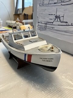
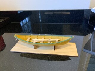
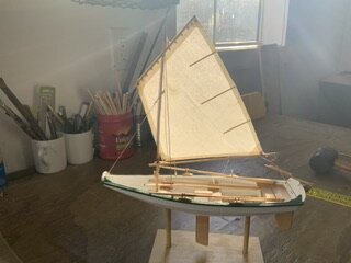
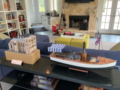
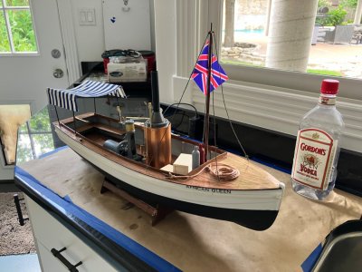
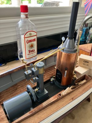
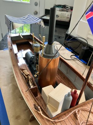
I have built a number of plastic and stick & tissue airplanes and a handful of boat models but this is my first attempt at so large a project. Here are photos of some past projects.IMG_3687.jpegIMG_3685.jpegIMG_0194.jpegIMG_0195.jpeg
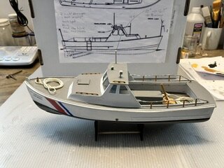
The African Queen will be different not only size but materials as well not to mention being RC and electric powered.

So here is what I have done so far.
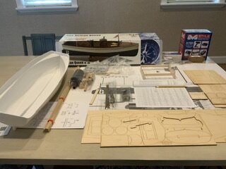
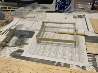
IMG_0191.jpegUnboxing. IMG_0192.jpegBuilt the cradle. IMG_0193.jpegReview parts

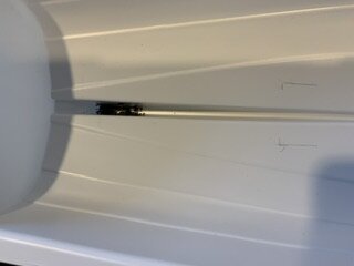
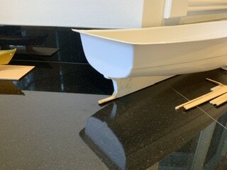
I also installed the rudder post which required cutting an opening in the hull which made me nervous.IMG_0196.jpegIMG_0197.jpeginterior view of the epoxied rudder support.
Next I have run into two situations that I could use a little guidance with:
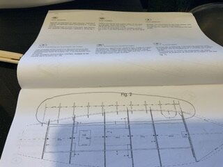
IMG_0200.jpeg The circled area says I should place the deck supports 49mm apart but the rule shows (circled) is a straight line vs the curved hull. Would not the hull curvature require more than 49 mm between supports? How would I calculate/measure that? Or am I overthinking this?

The other problem involves drilling another hole in the hull, this time for the propeller shaft. The instructions offer no measurements. Should I just shoot for the midpoint between the rudder support and the bottom of the stern overhang?

Any suggestions would be appreciated. Please also bear with me as I learn my way around building a Build Log!
 
Brother Gordon:
Will the deck supports show on the completed model? If not, no further thinking is required. If they will show you would want them to be spaced nicely. Start by measuring 49 mm intervals along the sheer with pencil tick marks. That will probably look fine but, if not, you can adjust a tad. Regarding the propellor shaft, I would place the prop in position with any washer and drive dog and move it until you have the same clearance top and bottom. This will probably be the same as the midpoint between rudder support and the counter.

One thing to remember with this project is that the African Queen is a fictional boat invented by a film crew. Therefore, accuracy is a bit hazy. Some years ago, I saw a 1:6 model of the African Queen in the lobby of a hotel on the harbor in Annapolis. That model was used in filming the scenes of the boat going down the rapids. Looks like you'll have a fun RC boat there.
Have fun!
 
Andy A,
Thank you for your response…particularly the reminder that this is a fictional craft. I tend to be an inveterate rule follower so if the instructions say 49mm that becomes the 11th Commandment. I’ll try to lighten up a little bit.

Thanks again
Gordon
 
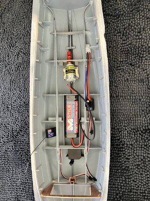
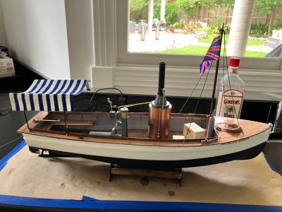
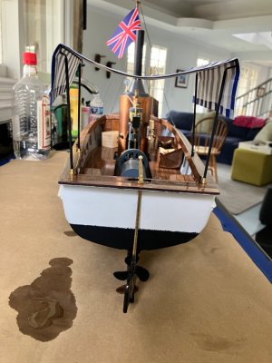
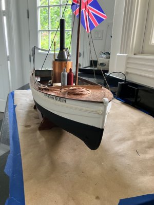
I have been remiss in my Build Log for the African Queen…I plead medical issues, procrastination and rookie dithering. But now I have figured out a few of my road blocks, principally how to layout the RC running and steering gear. My solution came from another Build Log…imagine that. Anyway, below is where I am now AND my latest problem.

The top photo is the rough layout of the RC steering and motor and the next down is the painted hull. I failed to seal the tape properly to the hull while painting leaving me a messy waterline. I will cover that with some 1/16” black art tape.

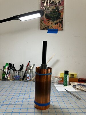
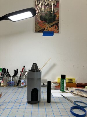
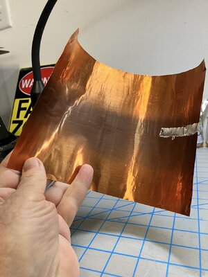
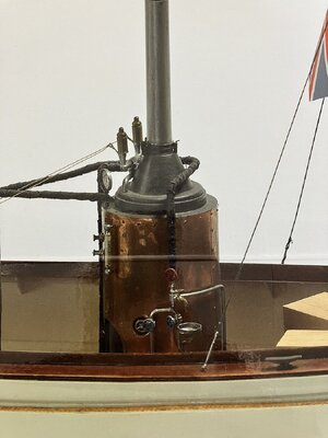
The thumbnails that follow are of the boiler (PVC pipe), copper sheathing and how the sheathing will wrap around the boiler (and be trimmed, etc.). Where I need advice is in how to make the boiler rivets so that it will resemble the last photo. The copper sheet is quite thin so I am fearful of using a punch-like tool to give the appearance of rivet heads and magic marker dots look pretty lame. My wife suggested pin heads glued to the copper sheet, but WOW! that would give me permanent crossed eyes and a bad back. In the same Build Log I ”borrowed” the steering and RC layout from looks as though he used a leather embossing wheel to make the rivet heads but I have not yet found such a tool.

Any thoughts?

IMG_4351.jpegIMG_4352.jpeg
IMG_4353.jpegIMG_4355.jpegIMG_4356.jpeg

IMG_4357.jpeg
 
The thumbnails that follow are of the boiler (PVC pipe), copper sheathing and how the sheathing will wrap around the boiler (and be trimmed, etc.). Where I need advice is in how to make the boiler rivets so that it will resemble the last photo. The copper sheet is quite thin so I am fearful of using a punch-like tool to give the appearance of rivet heads and magic marker dots look pretty lame. My wife suggested pin heads glued to the copper sheet, but WOW! that would give me permanent crossed eyes and a bad back. In the same Build Log I ”borrowed” the steering and RC layout from looks as though he used a leather embossing wheel to make the rivet heads but I have not yet found such a tool.

Any thoughts?
Looking good! A couple of thoughts:
1) It looks like you are wrapping the copper around a plastic boiler. Depending on the density of the plastic, you may be able to push sequin pins through the copper into the plastic. Sequin pins are about 1/2" long. If the plastic is too dense for that, you could drill pilot holes with a pin-vise and a tiny twist drill.
2) Do you need the copper? You could paint the boiler with copper-colored paint and other colors. Realistically, copper on a real vessel wouldn't look like shiny metal for long. The surface would soon turn into some combination of black, brown, and verdigris, which would be easy to represent with paint. You would still have to come up with some way to show rivet heads.

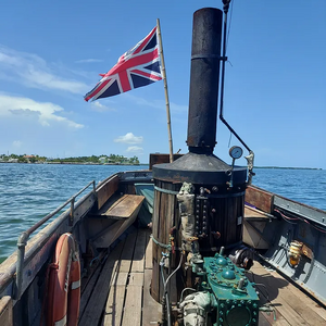
After I wrote the above, I googled around and found a good photo of the boiler in the African Queen that is moored in Key West. The boiler has wood staves strapped to it! That's probably a good safety measure. The part of the boiler showing below the wood looks kinda dark and dirty. Check it out!


1706803311479.png
 
AndyA,

Thanks for your input again. The boiler body is 1/8” pvc so I would definitely have to drill pilot holes for the sequin pins.

I just discovered a potential source for rivet heads…www.tichytraingroup.com
 
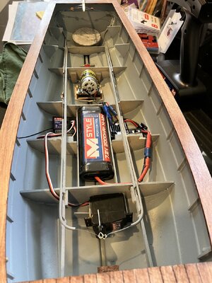
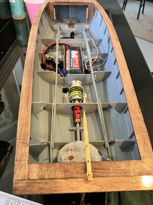
After much hemming and hawing I finally got the RC and running gear installed. I pretty much gave up on matching some of the pristine layouts I have seen from others’ builds and kinda crammed it all in and took it for a spin…just the hull and runnning gear.
IMG_4450.jpegIMG_4451.jpeg
Note the lead ballast fore and aft. I could use some suggestions for a better ballast arrangement. I have heard of lead shotgun shot and baggies containing sand. Any other ideas?


Here is Builders Trial #1: https://share.icloud.com/photos/05dlJT0KVDCe_f931OCFYtueA
Dunno if the link will really work but if it does you may notice that the turning radius for the Queen is far too wide, so back to the drawing board.


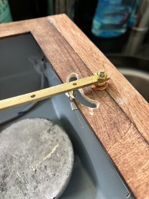
So here’s what’s I did to improve the steering:
IMG_4474.jpeg
I attached the steering cables much closer to the pivot point and removed most of the slack in them as they run from the bow-mounted servo back to the tiller arm. In doing so I had to cut into the deck and have to now figure a way to clean that up. Arrrrgh.


So here is Builders Trial #2: https://share.icloud.com/photos/0e736CjxbaRWPZkZInYMLkHYg


If you can access the iCloud link you will see the turning radius is much improved. So now I have to put in the deck, faux steam engine, Rosie & Charlie, and all the rest BUT, she goes!
 
I'm also building the Queen, so I will keep an eye on your progress .
I like how you have set up the steering servo, with the wire thru the tubing, and the push pull design.
And keeps the servo out of sight.
I have not yet got to that stage of mounting the servo, but it will be interesting.
And yes she is turning better now .........
 
Last edited:
Good luck with her and thank you for your kind words. Another member gave me some very sound advice: “Remember the African Queen is an imaginary boat” so strict adherence to “scale” and detail is not necessary. We should let our artistic imaginations run free. In other words, “Don’t get hung up on the details”.
 
Back
Top