• Ships of Scale has incorportated an extra level of security when you log In. Please follow on-screen prompts to acknowledge that you are not a robot via a "Check Box" or a "Pictorial Check Box Puzzle". This is needed due to higher level of AI Activity Security.
  • SUBSCRIBE TO SHIPS IN SCALE TODAY!

    The beloved Ships in Scale Magazine is back and charting a new course for 2026!
    Discover new skills, new techniques, and new inspirations in every issue.

    NOTE THAT OUR NEXT ISSUE WILL BE July/August 2026
  • Win a Free Custom Engraved Brass Coin!!!
    As a way to introduce our brass coins to the community, we will raffle off a free coin during the month of August. Follow link ABOVE for instructions for entering.

Albatross by CharlesEdward – Constructo - 1/55 –

Joined
Aug 11, 2026
Messages
117
Points
78

Location
Townsend MT
September 1, 2026

While I am waiting for USPS to find my lost shipment of Model Expo paints, I will start this build log for this simple model by Constructo.

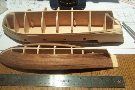
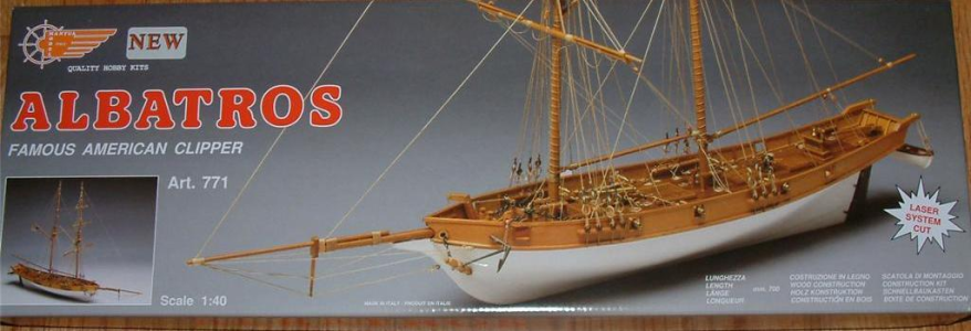
Purchased and received in early 2010, I wanted to compare the OcCre model kit with this one for the same vessel. I still don’t quite understand the scale of each kit; comparing the scale of this model of 1:55 to the scale of the OcCre Albatross which is 1:100. The OcCre Albatross kit is larger than the Constructo Albatross kit?

The Constructo model is on the bottom half of the photo, the OcCre model is on the top half of the photo looking at the decks..
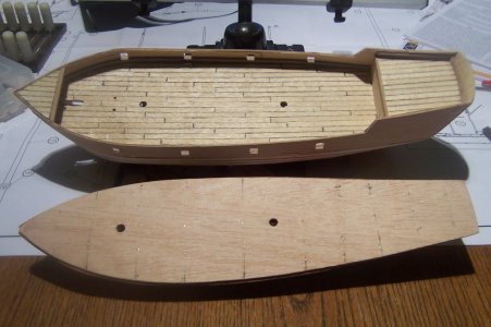
100_1396.JPG
Comparing the Port sides of each model.
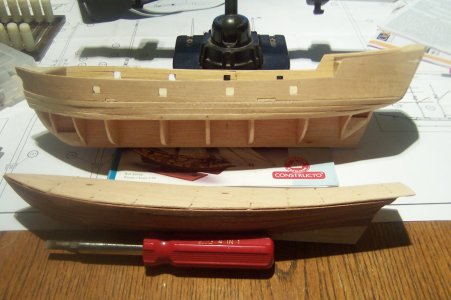
100_1397.JPG
The hull structure of each model.
100_1398.JPG

The Constructo model comes with an assortment of wood stock and metal pieces, with a color instruction manual in seven languages and pictures to follow the construction process. There is only one plan sheet and a Sail Sheet to help complete the included silk printed sail material. But you have to cut out, hem and rig each sail, so not sure if I have the patience for this now. The OcCre kit comes with totally cut, prepared, hemmed and rigged sails, such a treat.

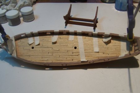
I constructed the hull as shown below and almost completely planked it but still have to finish it up. I spent an hour or more last night identifying all wood sizes and marked the corresponding part number reference in the manual. I found each and every part number, wood stock size to use and measurements in mm.
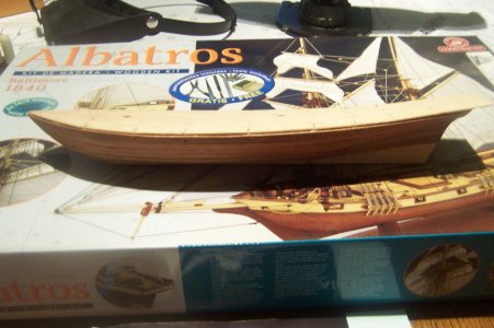
100_1384.JPG

Not shown but the two 6.0 mm. dowels included in the kit is used for both main and fore mast and will not fit in my mini-lathe to taper them without destroying the wood, or any of the yards. I will use the old hand drill and leather glove method; holding sand paper and locking the old Craftsman drill to taper them as best as I can. Or I could just hand sand them, a tedious process, but it just might be the best way.

I technically purchased this kit and the OcCre kit to begin this hobby with two easy kits, but as it turns out a tad simpler and relaxing modeling project has been started. Probably as fill-in work while waiting for Montanes and Sao Miguel glue to dry, or other time passing steps to do.

The colored manual is in seven languages with photos to show the step of the construction process. The next three photos show what the instructions are like; the manual cover, the left side is the printed instructions with part number size in mm. if it is wood, metal, mast / yard dowels, or cotton rigging thread, while the right side shows the steps to follow.
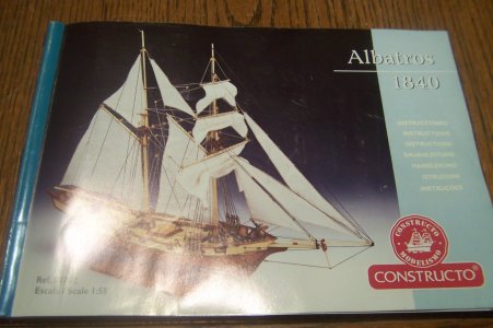
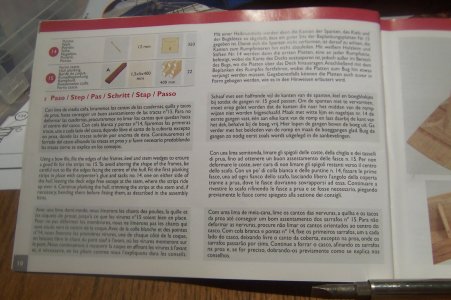
100_1385.JPG

100_1386.JPG

Instructions, with part number sizes and materials, colored photos on the right depicting the processes outlined in words on the left.
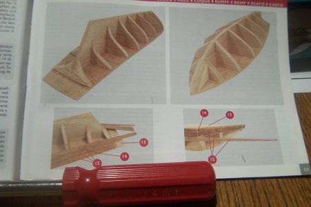
100_1387.JPG

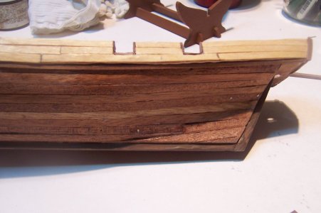
A photo showing the partially completed hull planking, this is only single plank of bulkheads with the planks being 1.5 x 5 mm. Sepella wood, not an easily bendable plank.
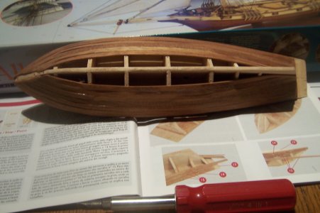
100_1388.JPG

The kit does supply deck planking using 0.5 x 5 mm. planks, which are used for multiple additional areas; the planking of bulkheads, bulwarks and etc. I will use a 50 - 55 mm. and 60 - 65 mm. strip, (about 10 to 12 foot planks in real life), in a four-staggerd four arrangement.
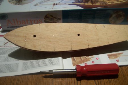

100_1389.JPG
 
Charles, I purchased a really old constructo kit of the Dos Amigos at a model swap meet which to my surprise had no instructions. The kit had all the parts and wood and the price was right. I figured I could just looks this kit up on line and find the instructions and reference materials that were lacking, nope. This was prior to finding Ships of Scale and all the builds done by members which might have made my search more successful. I ended up finding the ship on OCCRE but as you noted the scale was different. I got their instructions off line which was of some help in the assembly process since this was only my third wood ship build. The ship model itself resembled the Dapper Tom which I had just finished so I basically ad-libbed it copying the rigging and chocked it up to practice. All in all it turned out fairly well. I will enjoy watching your build if you continue.
 
Charles, I purchased a really old constructo kit of the Dos Amigos at a model swap meet which to my surprise had no instructions. The kit had all the parts and wood and the price was right. I figured I could just looks this kit up on line and find the instructions and reference materials that were lacking, nope. This was prior to finding Ships of Scale and all the builds done by members which might have made my search more successful. I ended up finding the ship on OCCRE but as you noted the scale was different. I got their instructions off line which was of some help in the assembly process since this was only my third wood ship build. The ship model itself resembled the Dapper Tom which I had just finished so I basically ad-libbed it copying the rigging and chocked it up to practice. All in all it turned out fairly well. I will enjoy watching your build if you continue.
I will continue this log, but at a slower pace, as I plan on concentrating on the Montanes for now until its completed; followed by the Sao Miguel in a few months’ time or so. Then onto the continuation of the Wappen von Hamburg until finished. I estimate that completing those two kits will take me into late 2027 or so.

I just did a little work on these two kits of the Albatross when I first received those kits in 2010, just had to fit the bulkheads to the false keel, and continued until, well you can see the postings. I just HAD to post them, like a teaser, getting my muse fueled up for building once again, and BTW these photos were new just taken today. I will, however be doing some work on both of my Albatross kits while pausing the Montanes while glue, paint drys and etc. Do check in now and again won't you?
 
September 3, 2026

I had moved a few tools into the house so I could work on the two Albatross models, when I got the itch to work them, consequently I worked a bit on the Albatross by Constructo. So I finished up the hull planking and starter planking the deck, as well as working the rudder part to cut three notches in the rudder for its hinges installed later.
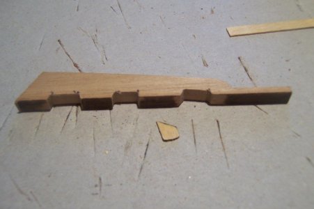
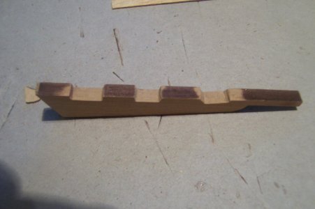
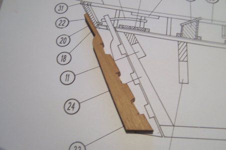
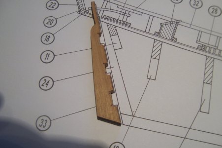
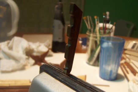
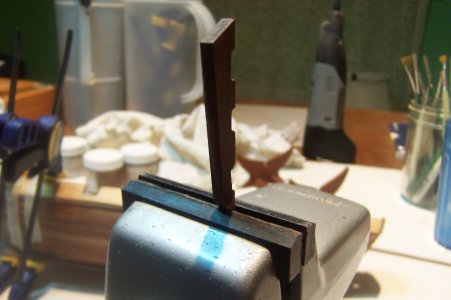
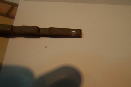
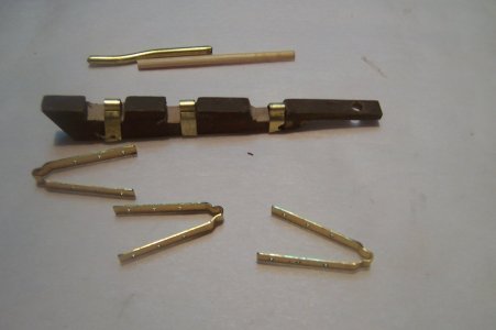
While waiting for the 1.5 x 5 mm hull strips included in the kit to soak for a bit, I worked the included precut walnut rudder part to include three notches for the brass hinges, to be installed later, using a small X-Acto saw to start the incisions matching the plan sheet showing that part, (see photos below). I than used a series of increasing width needle files to get the nicely squared cuts. Quite happy with the results, I had thought that I could have broken that part if I was too heavy handed with my filing.

100_1413.JPG

100_1414.JPG

100_1421.JPG

Direct comparison to the finished part against the plan sheet.

100_1424.JPG

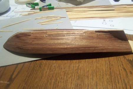
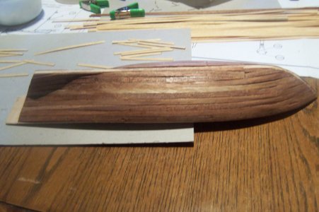
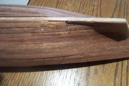
To the hull planking work now: After soaking the planks enough I brought them out and started to plank the hull per instructions. Strake by strake starting from the wale and moving downwards to where the keel will be added later, (the keel is installed after the bulwarks and deck planking are complete). Planking requires patience and exact measurement, measuring two or three times before cutting. Anyway after a few hours of work, the hull was fully planked.

The Port Side:

100_1406.JPG

The Starboard side.

100_1407.JPG

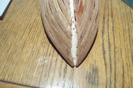
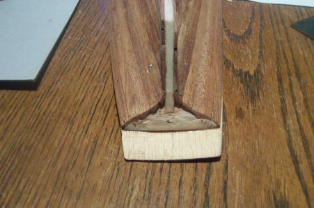
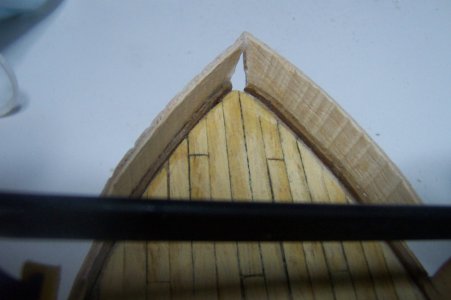
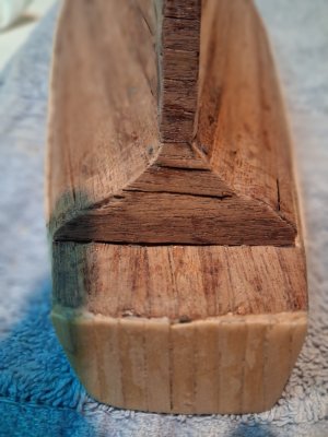
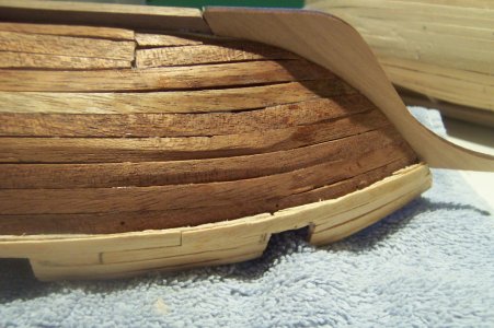
Some closeups of the Hull Planking; first the bow. There is a keel and prow and stern post that get installed into these channels.

100_1408.JPG

100_1409.JPG

100_1410.JPG

100_1411.JPG

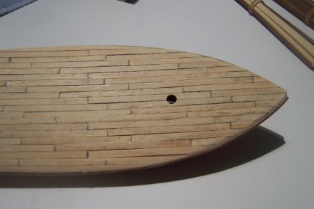
On to the deck planking, now I decided to use a 10.5-to-12.5-foot planks, which at 1:55 scale would make the wood strips anywhere from 64.0 mm to 76.2 mm in length, (per a google search, wonder how accurate that is?). A six-foot human would have a standing height of approximately 34.4 mm.


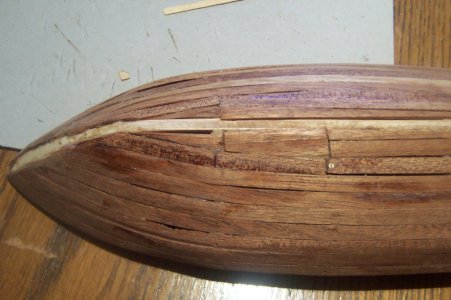
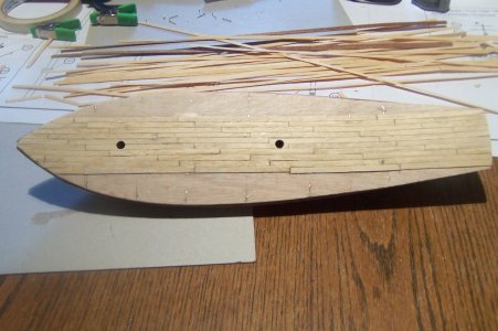
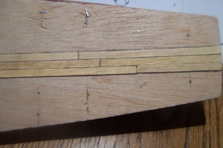
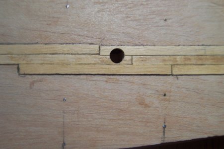
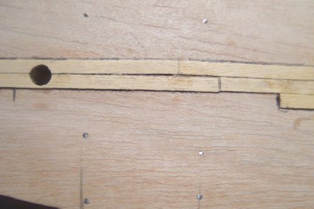
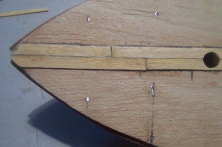
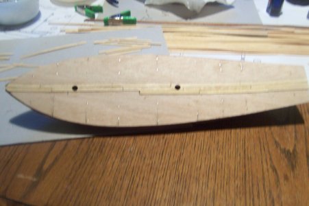
I used the supplied wood of 0.5 mm thickness x 4 mm width. I cut about three or four of the 400 mm planks included in the kit and cut 15 or so deck planks at a length of 64 mm and 76.2 mm to start. Used a soft lead pencil to darken the edges all around the plank to simulate the tar used back then. I started from the CL of the deck toward starboard to install the first row of deck planking as accurately as possible. I am planning to use a 4-plank stagger pattern on the deck, which I believe means that ever 4th joint seam of the deck will be matched or there will be three strakes of planks between those matching joints. You can see the deck pattern starting in the photo. I alternately did a Port side row for every Starboard side row installed. So back and forth from the Starboard and Port sides, sanding after each row had dried trying to get a very smooth planked deck.

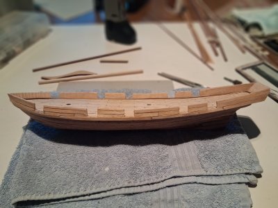
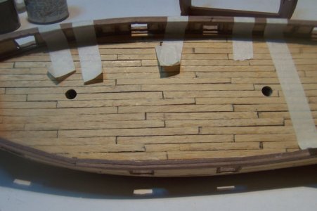
This photo is of the partially finished deck planking, you can start to see the pattern developing. I mostly had to custom cut the planks to match up with the staggered decking. This is where I ended up for todays work. I will complete the deck planking tomorrow and get back to painting the Montanes gun ports and complete those parts, getting ready to install them on that model.

100_1428.JPG

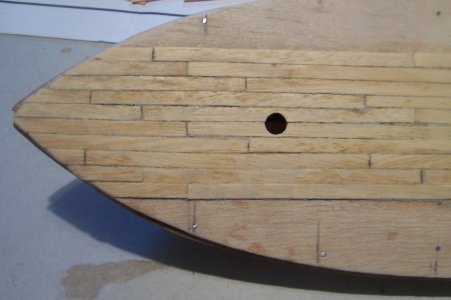
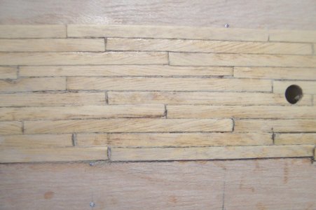
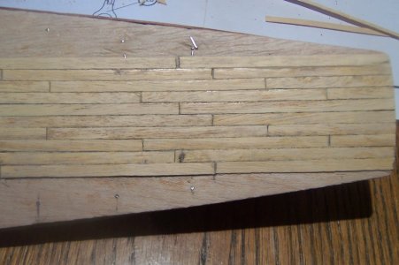
The next photos are closeups of the deck planking before I quit for the day.
The bow area:

100_1429.JPG

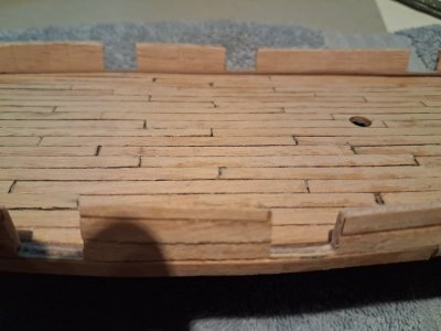
The Midships area:

100_1430.JPG

The stern area:

100_1431.JPG

The next three photos are of the completed deck planking on the OcCre Albatross kit for comparison:

100_1425.JPG

100_1426.JPG

100_1427.JPG

100_1399.JPG

100_1401.JPG

100_1402.JPG

100_1403.JPG

100_1404.JPG

100_1405.JPG
 
September 4, 2026

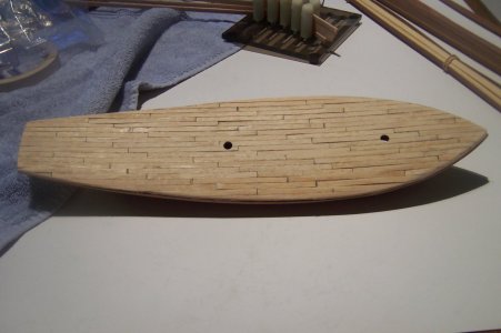
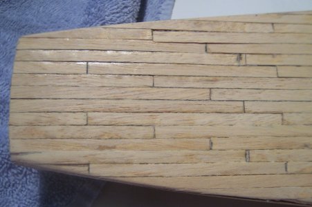
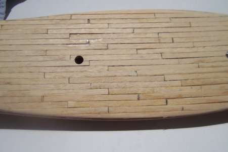
I finished the deck planking today, the next step is installing the waterways and that means some soaking of the 1.5 mm. x 3.0 mm. wood stock that needs to be bent to shape the model. Here are several photos of the finished deck showing the stagger pattern I used, with one mistake, we are our own worst critics, aren’t we?

First the entire hull planked with the four-stagger pattern with three planks before the butt is matched.

100_1433.JPG

The stern section of the deck.

100_1434.JPG

The amidship section of the deck.

100_1435.JPG

The bow section of the deck.

100_1436.JPG

I will get the bending of the waterways in a few hours.
Thanks for looking in, until next time.
 
Charles please do not forget the Baracado. This ship transported enslaved people. Therefore it had a Baracado to separate the ships crew from the enslaved people.

Ship looks great so far.
Bill
 
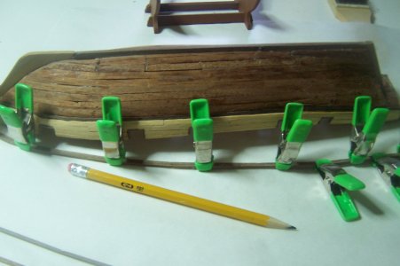
The waterways and bulwarks have been soaking for a few days waiting for the jig to be freed up to bend those to fit THIS model of the Albatross’ hull curvatures.

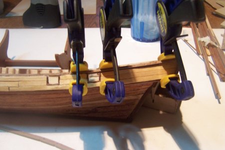
Then to install them along the deck in preparation for installing the one-piece laser cut bulwarks on either side, port and starboard. Which will be an interesting challenge for me and will make the shape of the model become more ship-like then it is now. I had to glue this in sections, starting at the prow to the first clamp, wait a few minutes, then continue placing CA along the next section edge, attaching clamp to dry. It took three sections to get this one installed.

Commented Port Waterway installation.png


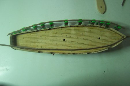
I successfully installed the two waterways on each side of the deck, port and starboard and the stern waterway. Sanded it all down and am waiting for the bulwark pieces to dry in that jig a bit before I can install that very important piece. Here is the port side waterway in place.

20260906_115928.jpg


Here is a photo looking toward the starboard waterway in place.

20260906_115948.jpg


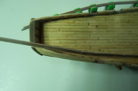
The stern waterway in place, all ready for the installation of the Bulwarks.

20260906_120005.jpg


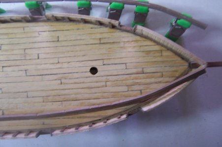
Three closup views of the port side waterway installed, this one in the bow third of the model.

20260906_103946.jpg


Photo of the amidships section.

20260906_103955.jpg


Finally the stern section, I cut off the overhanging section to allow room for the stern waterway to be installed.

20260906_104001.jpg


Thanks for checking in, until next time.
 
Charles please do not forget the Baracado. This ship transported enslaved people. Therefore it had a Baracado to separate the ships crew from the enslaved people.

Ship looks great so far.
Bill
I don't remember reading about this, but I suppose it is quite possible that these types of ships were used for transportation of slaves. My research seems a bit lacking to miss an important history of that. It is not mentioned in the kit instructions, so probably not included in this model kit. I am not good enought to scratch build ship models yet. Just enjoying the scratch built examples displayed on this website.
 
September 7, 2026

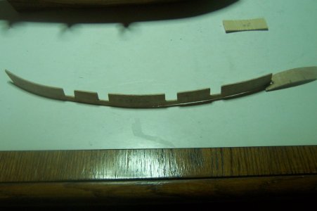
I totally misread the precut part for this model; I was using the prow end for the stern and the aft end for the prow. It was confusing me and the part fit better once I matched prow to prow end and stern to aft end.

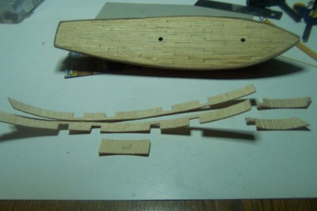
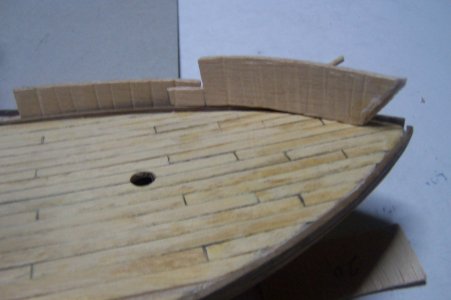
The bulwarks were precut and looked easy to install but have become very difficult to install onto the model, probably because I only have a 3 mm. plank to attach it to. Very hard even for fast drying superglue so I decided to cut the piece in two to better handle what the instructions said to do “glue the prow ends together”, sanding to fit them which did not turn out the way I wanted it to. So the precut parts became two, the small bow section and the rest of the bulwark precut piece. I also bent them using the plank bender pliers to the correct side of the part.

01.JPG

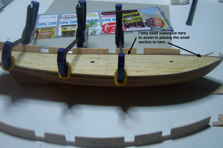
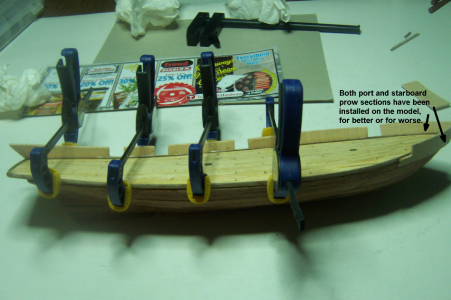
I glued the port bulwark large piece in place using CA in only one place, using clamps to locate the part on the hull correctly. Then superglued the port prow section in place trying to match the join the cut together. Then I superglued the starboard prow section in place trying attach it to the port prow section.

02 - Comment.png

The fully integrated two-piece bulwark in place, using mostly white wood glue for the long section and superglue for the prow section.

08 Comment.png

Dry fitting to compare my adjustment for this part to see if it is possible.

03.JPG

Showing the inside of the Port amidships bulwark installed.

04.JPG

Showing the inside of the port bulwark stern / aft section.

05.JPG

A closer photo of the bashed part.

06.JPG

The installed port prow section looking toward the port side.

09.JPG

The installed starboard prow section looking toward the starboard side.

11.JPG

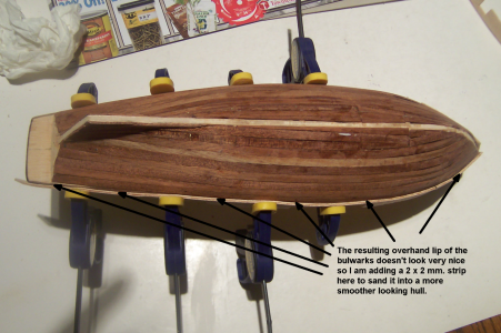
The assembled port side bulwark looks a bit awkward as the bulwark piece over hangs the hull planking by 2 mm. I think I will use a 2 mm. x 2 mm. board and place it along the lip of where the bulwarks and hull join, then sand it a bit to look like more of a smooth transition from the hull to the bulwarks. Look at me, bashing a kit….oh my. I could have added the strip BEFORE I installed the bulwark, it would have been a bit easier.

12 Comment.png

Thanks for checking in, until next time.
 
September 8, 2026

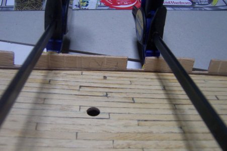
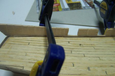
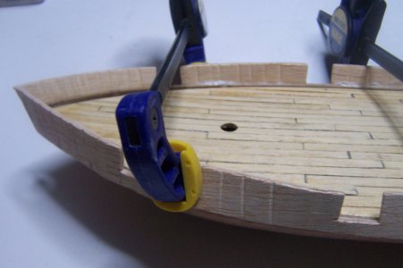
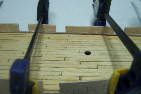
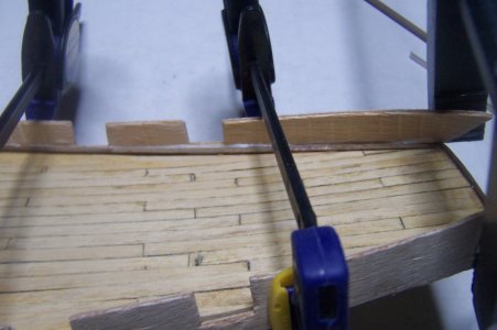
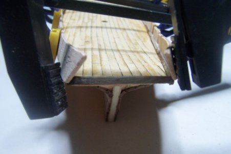
Well I am thrilled that the bulwarks are done, I installed the starboard bulwark using ONLY white wood glue and clamps. Superglue can be difficult to work with some times, but in this case, the freedom of being able to move the part slightly to perfect the position was great!

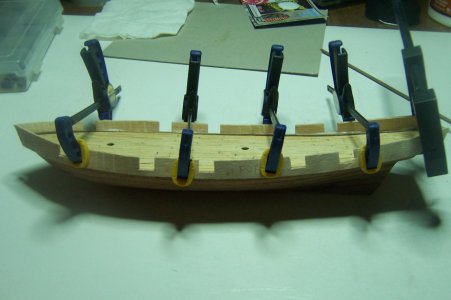
A photo of the starboard bulwark in place looking towards the starboard side of the model with clamps in place. I am going to wait a bit to ensure that the white wood glue has set securely before I remove the clamps to a series of ‘clean’ photographs of all of the bulwarks in place.

01.JPG

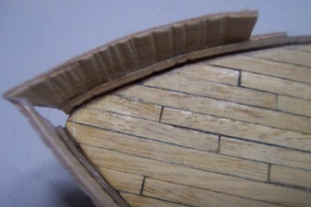
The next three photos are closeups of the bulwark; first the bow / forward section of the model. I wiped the white glue residue off after I took this photo, but the glue is supposed to dry clear anyway.

02.JPG

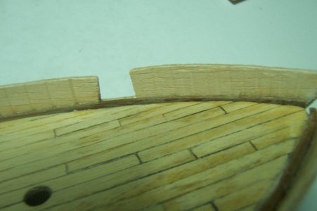
Next the amidships section of the model. The creases or scoring you see on the inside bulwark are from the plank tapering pliers I use to get a better or worse curve of the piece. The instruction do not say to line the inner bulwarks, but I might do so anyway to hide the scoring. The instructions do say to line the outside of the bulwarks with 0.05 mm. x 5 mm. Sapelli wood strips. I might repeat the process on the inner bulwarks.

03.JPG

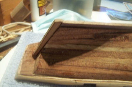
The stern after section of the model. I still like the stagger pattern of the deck planking and I will use sponge sanding of coarse to fine to very fine to clean it up some more, before I varnish it, (maybe).

04.JPG

Looking at the way the after section of the model looks, with a more severe angle to the deck than I actually wanted, but I will work it a bit to fit the stern bulwark piece in place just right.

05.JPG

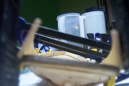
Looking from the stern towards the bow / prow of the model just to see the effect so far. The two pitchers you see in the background are where I store my clamps, the Irwin clamps in one ant the black pressure clamps in the other.

06.JPG

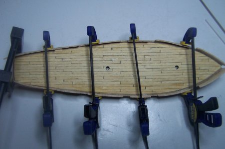
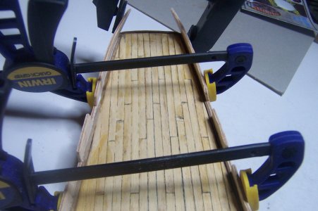
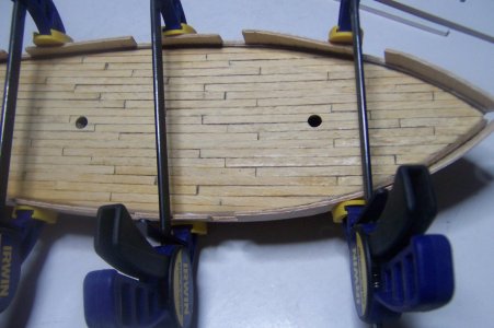
The next set of photographs to show the overhead view of the drying starboard bulwark, followed by a better view of angle of both bulwarks at the aft section of the two sides together, and then the bow / forward section of the model. Birds eye view of the model with port / starboard bulwarks in place.

07.JPG

Overhead angle of the aft port / starboard bulwarks drying in place.

08.JPG

The bow / forward overhead view of the drying bulwarks in place, for better or worse. Again the staggered deck planking is noted to be pretty good, for my amateur modeling standing.

09.JPG

The bow / prow section; the instructions call for a 0.6 mm. bowsprit hole to be drilled here. It will be cleaned up before the end.

12.JPG

I can’t tell you how good it feels to be done with these two complicated, (to me anyway), bulwark pre-cut parts. I will attach the stern bulwark later working the pieces together and post those photographs for your enjoyment.

Thanks for checking in, until next time.
 
September 9, 2026

Whole lotta lining going on today, completed the bulwarks by adding the stern bulwark part #20, then lined the outboard side with vertical strakes, sanded several times to get a smooth surface. [photo 07]

07.jpg

The instructions call for lining the outboard bulwarks with .05 mm x 5 mm Sepelli wood strips. Instead of using the full 400 mm strip to line I decided to cut the strips into 18-to-25-foot planks, around 115 mm in length using the 1:55 scale calculations for this model.

After cutting a small stock of planks the length I wanted, I lined the port and starboard bulwarks also on the outboard sides. Sanded everything down from course to very fine sandpaper to get a smooth appearance of the model.

The starboard side facing port.

02.jpg

The port side facing starboard.

01.jpg

Amidships both port and starboard.


03.jpg

04.jpg

Port stern section facing starboard.

05.jpg

Starboard bow facing port.
06.jpg

The next step is adding the stem, sternpost and keel, knowing this I dry fitted the main bowsprit and stem together to ensure the proper angle of the bowsprit will be attained. I had to do some clean-up sanding on the prow hull to fit the pre-cut 4 mm stem securely. The pre-cut sternpost fits perfectly so all that is left is to trim the keel so that it fits together between the stem and sternpost.
I will post that activity probably the day after tomorrow of so.

Thanks for checking in, until next time.
 
Setptember 10, 2026

Photos from the old Kodak digital camera take up a LOT less file size than my phone photos do. I will probably use the Kodak from now on as it allows me to upload more photographs to meet the size limit for Model Ship World and 10-limit number of pictures for Ships Of Scale.

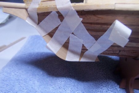
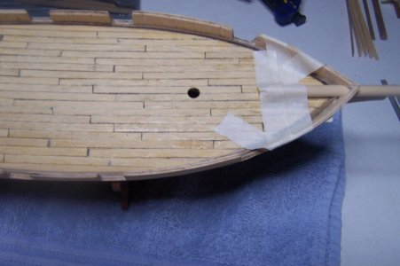
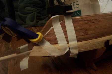
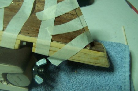
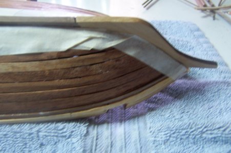
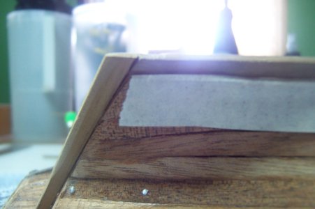
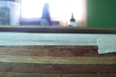
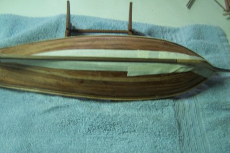
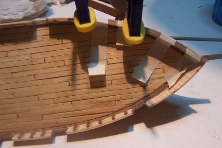
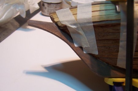
I was thinking about how to cement the pre-cut stem piece to the model and to ensure that the bowsprit is positioned at the correct angle at the same time and came up with this idea. I really have never used masking tape to do this on any model, or at least I don’t remember doing so. She is sitting on the OcCre Albatross cradle for these photographs. I will use the white wood glue so I can move the stem around a bit to perfect the fit.

06_Another_Closeup_Port Stem Jig.JPG

Secured the bowsprint to ensure its proper angle and that the Stem will match it when it comes time to install the masts and yards.

03_Overhead view of secured Bowsprit.JPG

I Used two clamps to keep the stem tight against the prow while it was setting.

12_Stbd View.JPG

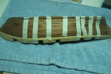
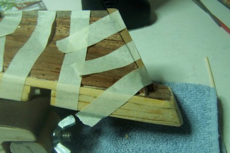
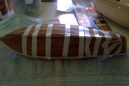
After about one hour, I removed the tape and started working on fitting the keel to the hull. There is a 30-degree angle on the Stem, so I have to match that by sawing and sanding the 4 mm x 4 mm stock that the keel is made of. The instructions said that the keel should be 240 mm in length, which I cut and then measured the angle and cut that again. Dry fitting the keel with the sternpost there is another similar angle at that end, so cut and sanding again to fit. Once that was done, I cemented the keel in place using masking tape to hold it tight against the hull.

100_1529.JPG

While waiting for the glue to dry I sanded the sternpost and dry fitted that against the keel, it didn’t quite fit and I had to do some sanding to get the sternpost to fit as it should, against the keel and stern of the model.

100_1537.JPG

With the sternpost and keel set to dry, I continued some planking of the OcCre Albatross model.

100_1536.JPG

The assembly waiting for the glue to set for 30 minutes.

100_1539.JPG

After just over 30 minutes of waiting I removed the masking tape and voila, the Stem, Keel, and Sternpost all assembled.

100_1540.JPG

The joined keel and stem pieces, sanding some to smooth the look. I may insert a small strip of .05 mm. board to hide the small space between the two parts, if you noticed it.


100_1541.JPG

The joined Sternpost and Keel, fitting pretty good.

100_1542.JPG

Thanks for checking in, until next time.
 
September 12, 2026

This step of the instructions wanted me to install 37 rough tree timbers from 1 x 2 mm. timbers at 13 mm. in height, (part #29), 2 bulwark tops from 1 x 3 mm. using 20 mm lengths, (part 30), three bulwark stern gallant railings from 2 x 2 mm boards using 50 mm length, (part 31).

Instructions wanted to install the three parts 30 one at a time gluing the center gallant rail first on the stern bulwark, (part #20), then install one gallant rail inboard and one gallant rail outboard separately. I got to thinking that the better way to do that would be to glue all three pieces together then glue that stern gallant rail assembly onto the stern bulwark top all at once. I could sand it and make it fit much better and it seems more efficient to me then by following the instructions.

Here are the three parts #30 glued and shaped together ready to install on the stern bulwarks.

01_stern gallant railings.jpg

Finally, to be posted next time, part 32 4 gallant rails, two on the port and two on the starboard bulwarks tops which would have to be bent to the shape of the bow area; so I put those four planks in to soak and continued with working and installing parts 29, 30, and 31.
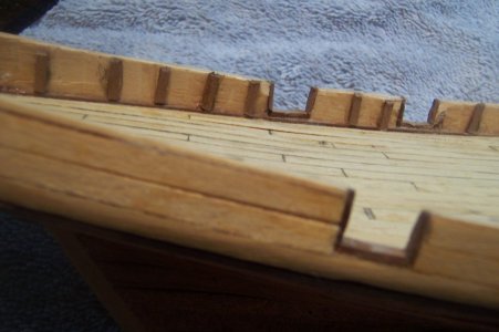
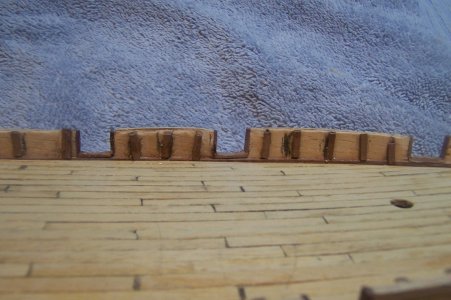
Looking at the model deck and the 1 x 2 mm. wood stock marked for cutting the 10 – 11 mm. height to fit the bulwarks of the model and the assembled stern bulwark gallant rails.

02_Port side of the model.JPG

The starboard side of the model with the gunport frames trimmed and cleaned up removed all extra wood debris before the rough timbers have been installed.

03_STBD side of model.JPG

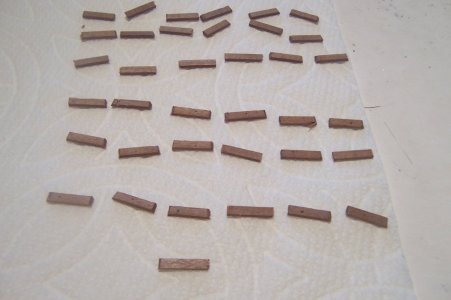
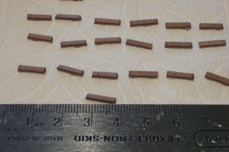
The 37 part #29 cut and sized but not yet sanded.

04_37 part #20.JPG

A closer view of part #29 with a 6” ruler for reference.

05_part #37 with ruller.JPG

The stern area showing port and starboard forward gunport frames cleaned up.

06_Stern view looking port.JPG

The bow area showing port and starboard forward gunport frames cleaned up.

07_Forward Prow looking port.JPG

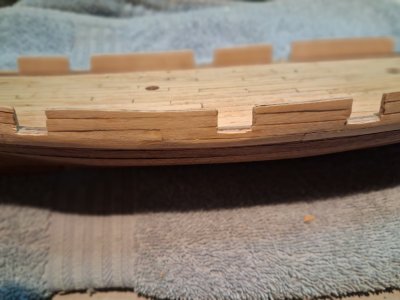
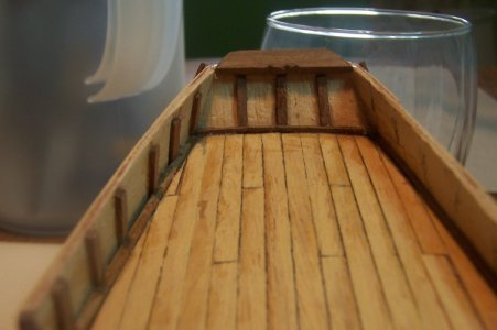
The stern bulwark with the rough timbers installed.

08_timbers installed stern bulwark.JPG

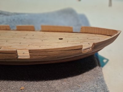
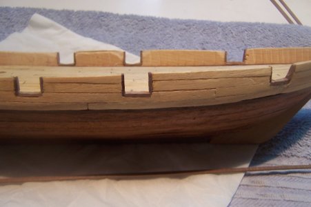
The aft area showing the installed rough timbers not quite cleaned up yet.

09_Timbers installed stern area.JPG

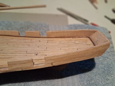
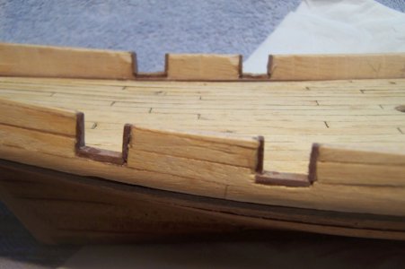
The bow area showing the installed rough timbers, not cleaned up yet. [

10_Timbers installed forward area.JPG

I will cover the main bulwark gallant rail installation next time.

Thanks for checking in, until next time.
 
Last edited:
September 13, 2026

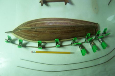
As promised this post will follow the installation of part 32; which consists of 4, 2 x 2 mm wood stock around 400 mm in length. The main bulwarks gallant rails, two on the port and two on the starboard bulwarks tops which would have to be bent to the shape of the bow area, so these 4 pieces of wood have been soaking a day and drying another day to kind of assume the shape of the bow area. Again just like the 3 stern bulwark gallant rails pieces, instructions said to glue the center one first then glue inboard and outboard pieces on either side of that aft center board, these were to be glued one at a time, shaped and trimmed on the inboard side, than glue on the outboard piece and round them a little. So following the same logic I will glue the two starboard gallant railing pieces together first, then the two port gallant railing pieces, AFTER I dry fit both of them and further bend them with my plank bender pliers to try to match the entire bulwark curves.

The port gallant railing pieces are drying, comparing the curvature of the port bulwark. The starboard gallant railing pieces toward the bottom of the photo have been curved to the approximate curvature of the starboard bulwarks and are awaiting their turn with the clamps.

01_Gallant Rails Part #32.JPG
Closeup photo of the starboard gallant rails, waiting for the port gallant rail assembly to dry.

04_Starboard gallanat rails not glued yet.JPG

The port gallant rail assembly closeup.

05_Closeup of Port gallant rails waiting to dry.JPG

An overhead view of the model with the starboard gallant rails finished awaiting glueing on the model, while the port gallant rails are just starting their drying cycle.

07_Overhead view of the Stbd and Port Gllant Railing Assembly.JPG

A dry fitting of the aft starboard gallant railings waiting to be glued onto the bulwarks.

08_Closeup of Stern Area.JPG

Dry fitting the bow area for the starboard gallant rails being glued onto the model.

09_Closeup of Bow Area.JPG

As I was waiting for the gallant railings to dry fully and be attached to the model, I rescued some old paint I had ten years ago by adding warm water to the Dark Brown and Spanish Brown Model Expo Acrylic paint bottles looking at painting the light-colored stem to match the keel coloring. The keel taping is just in case the paint I choose doesn’t match the keel color closely enough.

11_prep for painting the prow.JPG

The end of the keel taped, and wondering about the sternpost color now.

12_prep for painting the aft Keel.JPG

Taping the amidship keel in case I have to paint that also.

13_prep for painting keel amidships.JPG

Prepped for painting the stem, keel and sternpost.

14_overhead view of paintin prep.JPG

Coming up next; attaching both the starboard and port bulwark gallant rails in the next posting. Plus the result of

Thanks for checking in, until next time.
 
September 14, 2026

I was having issues with installing the entire port side gallant rail as one piece, so I cut it into a smaller bow segment that is easier to place and glue, and the longer segment that I might cut one more time in order to make the installation easier.

The bow segment of the port gallant railing, drying.

01_Port bow gallant railing.JPG

For some reason the starboard gallant railing fit nicely as one piece, go figure. The referenced gallant railing drying.

02_Starboard Gallant Rail fitted as one piect.JPG

The painted sternpost.

03_Painted sternpost and Keel.JPG

The painted stem.

04_Painted stem.JPG

The painted keel amidships.

05_Painted keel amidships.JPG

The painted rudder blade.

06_Painted Rudder 1 (1).JPG

The painted rudder blade other side.

07_Painted Rudder 1 (2).JPG

The aft segment of the port gallant railing, drying.

08_Stbd Gallant Rail stern.JPG

A 2 mm hole drilled into the rudder blade to insert the brass tiller once the rudder blade is attached to the sternpost, very slowly done but I still made it too large darn it.

09_Rudder Blade with 2 mm hole for brass tiller.JPG

The forward starboard gallant rails fitted as one piece and drying.

10_Stbd Gallant Rail.JPG

Coming up next time I take a breather and check the mast and yards to ensure all is there.

Thanks for checking in, until next time.
 
Last edited:
September 15, 2026

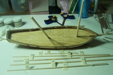
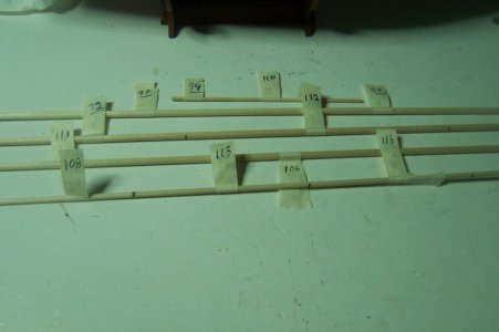
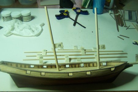
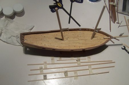
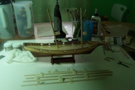
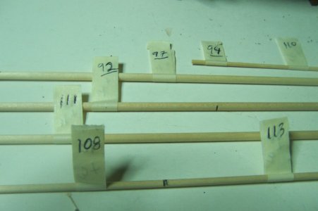
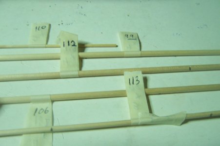
I felt that I had been working hard and concentrating on this kit instead of the Montanes, so I took a breather and looked ahead in the instruction book and fixated on the Masts and Yards sections of the manual. Realizing that I hadn’t taken any time with those dowels since I received the kit back in 2010, I decided to ensure that I had enough of the wooden dowel stock in the correct diameter and marked and cut the Main mast, Fore mast, and Main Bowsprit, shown on the model loosely dry fitted and yes, the Main Mast does have a deliberate angle to it, but the Fore Mast is perpendicular to the keel, if not the decks. The wooden dowels came in four different diameters, 6, 4, 3, and 2 mm, parts 91, 96, and 98 were included separately with lengths that were approximately close to the actual required size of the Bowsprit, Lower Foremast, and Lower Main Mast. Shown in the proper length on the model, but I have yet to taper any of the stock. There were three 4 mm, one 3 mm, and one 2 mm dowels include with the kit, and just enough of it to get all of the masts and yards done.


02_good photo of wood stock.JPG

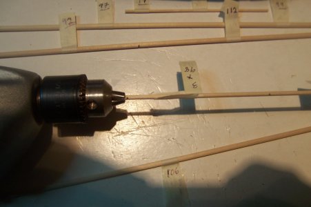
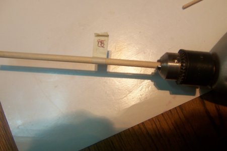
Since these particular dowels are all a bit too small for my Fox Mini-Lathe to use, (six-foot in length, weighs about 200 – 250 lbs. mini? yeeesh), so I did drag out my old trusty Sears Craftsman Lockable, Variable speed, and reversable plug-in drill, (that thing must be almost 20 years old by now, and still working like a charm), go figure USA Manufacturing Quality. I do have an actual small model lathe that is only around 24 inches long purchased from Model Expo or Micro Mart, but when I purchased several models that average close to 36 to 44 or 48 inches in actual length, that small lathe couldn’t help with the 10 to 15 mm diameter stock for those kit masts and the Craftsman works better with dowels less then 10 mm in diameter anyway.


03_Closeup of marked dowels.JPG

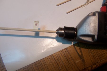
Anyway I digress, I use the Craftsman like a hand-held lathe, inserting the dowel into the chock, running on low to medium speed, and with a folded-up fine or medium sandpaper in my heavy-duty leather gloved left or right hand, I maneuver the sandpaper up and down the dowel to taper it to the required diameter, increasing or decreasing the pressure as needed to get the correct taper. Why the leather gloves, even at low to middle speeds the resulting friction produced can burn your bare hand badly. Masts are easy, but yardarms are a bit more tricky since you have to taper both ends, I am still practicing tapering model ship masts and yards manually as the manual details, each model is a learning experience in this process.

10_ Drill with part 98.JPG


A photo of the model in the foreground and the marked dowels in the background.

01_Starboard side of the model and all the dowels marked and measured.JPG

Another photo, somewhat in shadow of the model and marked dowels.

04_Shadowed photo of subject.JPG

Same photo but with only flash so it is much darker.

05_dark photo of subject.JPG

Closeup of the Marked dowels left side.

06_Closeup of marked dowels left.JPG

Closeup of the Marked dowels right side.

07_Closeup of marked dowels right.JPG
Next two photos is different views of the drill with a 3 mm dowel, (part #98) set inside the Chuck.


09_Drill with part 98.JPG


11_Drill with part 98.JPG

Coming up next time we will see the rudder blade being installed and maybe some davits also, since the rudder is only one piece.

Thanks for checking in, until next time.
 
September 16, 2026

Manual Page 38 of instructions: Deck Gratings installation.

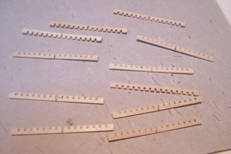
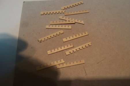
The instructions wanted the nice grating stock to be cut in half and to form three grated hatches of 6 x 6 holes. These are all marked to where I will cut them in two.

Photo_01 Deck Gratings.JPG

The grating pieces cut in half.

Photo_02 Deck Gratings cut in half.JPG

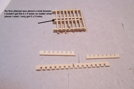
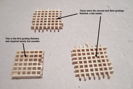
My first attempt was not clean and in fact I almost had to destroy it totally, it was so messed up. However with very careful sanding and judicious use of superglue, it was saved, well almost, but it will be cleaned up a bit before installation on the deck.

Photo _03 First of 3 gratings with comments.png

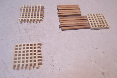
Instructions said use white wood glue thinned a bit by water and wait for them to dry. I then used a medium grit Dremel sanding wheel to trim the overhanging scrap beyond the 6 x 6 holes or 18 x 18 mm square grating hatches, followed by a fine sandpaper block to make the edges all smooth and once again checked the finished three grating hatches with the calipers to ensure all measured equally.

Photo_04 comments.png


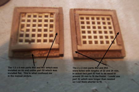
Then cut four different grating frames, parts 50, 51, 52, and 53, using 1.5 x 4 mm strips, and 2 x 2 mm strips. Each piece requires six frames of 1.5 x 4 x 18 mm, 1.5 x 4 x 22 mm, and 2 x 2 x 22 mm, and finally 2 x 2 x 26 mm. I measured and cut the 2 x 2 boards first, used a caliper to double check the length and adjusted so all pieces would match. I only show the 2 x2 boards I cut here, forgot to get a photo of the 12 pieces from the 1.5 x 4 mm.

Photo _05 Grating Frames #52 and 53.JPG

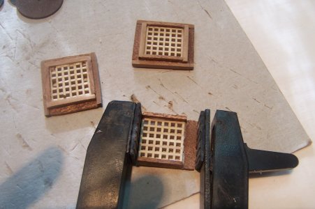
As it turns out most of the length measurements listed in the instructions for the grating frames were off and I had to measure the actual completed parts first in order to recut the 2 x 2 mm parts to fit better, (you can always cut them smaller but you can’t make them larger, can you?), glad I have extra 2 x 2 mm walnut boards in my lumber supply. Plus I didn’t quite understand what the picture in the manual was telling me about how to put the grating frames together. I finally got it though, and the three gratings are completed just have to sand and fit them to the deck curvature.


Following the illustration to install all the grating frames in numerical order, I than sanded the bottom of the dry assembly to match the deck curvature and position on the deck per the floor plan. The resulting three completed deck gratings. [

Photo_06 Two of Three Gratings done.JPG

Here is a close-up view of the first two gratings finished.

Photo_07 with comments.png

I am moving ahead in the instruction manual to several different deck furnishings, holding off on the Rudder Blade installation. Not sure which manual page I will post next. I did work a bit on the rudder but haven’t finished attaching it to the sternpost.

Thanks for checking in, until next time.
 
September 17, 2026

Page 28 of instructions: Rudder blade installation.

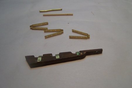
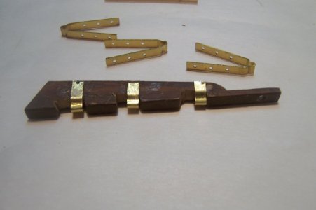
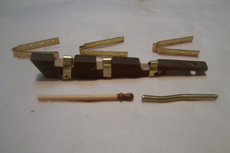
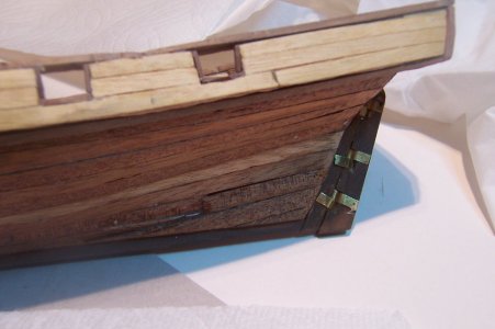
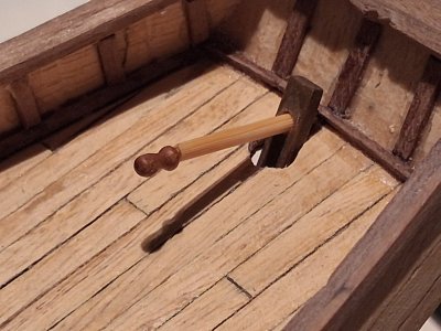
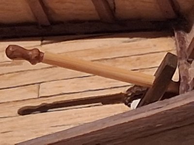
Requires part 14, nails, part 33 wooden rudder blade, which I have painted and drilled a 2 mm hole in for the brass tiller, part 34, six brass hinges cut to fit the blade and held in place by the nails. Then cut the 2 mm brass wire a length of 6 mm for three parts 35 hinge shafts and finally 26 mm for the rudder tiller part 36. I am thinking about using a toothpick instead of the brass wire with an extra belaying pin attached to resemble a tiller handle. We shall see how that turns out.

I also had to drill a 5 mm hole in the deck just above the stern post to pass the upper rudder blade through for the tiller control. Although the sternpost is centered properly the whole seems a bit out of whack and off center some. I will have to bear with it this time around.

Closeup of just the hinges and rudder blade with hinges installed.

Photo_01.JPG

Showing the edge of the rudder blade.

Photo_02.JPG

The toothpick tiller with a extra belaying pin I had lying around.

Photo_04.JPG

Manual Page 36 of instructions: Model stand installation.

Parts 45, 46, 47, and 48 consist of the pre-cut base, edging strips of 1.5 x 5 x 70 mm and 1.5 x 5 x 165 mm to attach to the base short / long sides.
This just seems inadequate for this model, kind of cheap and not very solid, I will have to think of modifying this to better suit the model.
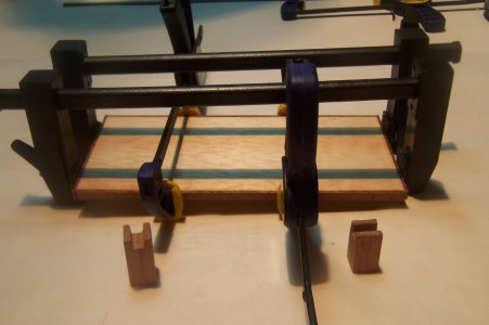
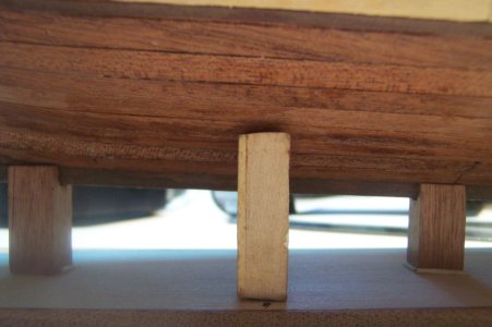
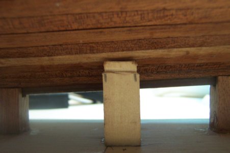
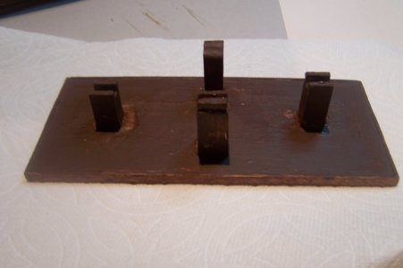
The base of the stand with the two edge pieces added and drying, the bottom of the photo shows what the kit included for supports, the notch is only about 2 mm and the keel is a 2 x 2 mm board, so I had to file it wider to accomodate the actual model keel.

Photo_05.JPG

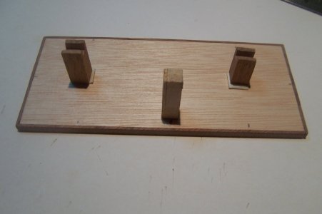
I figured a third support would be better for a more stable model stand.

Photo_06.JPG
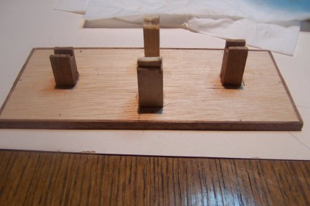
If three are good, wouldn't four be better? We shall see how it turns out.


Photo_07.JPGI

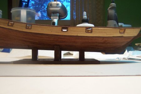
IStarboard side with the model on the stand.

Photo_08.JPG

The added support on the starboard side of the stand.

Photo_09.JPG

The port side support.

Photo_10.JPG

Coming up, I will try to post the actual installation of the Rudder Blade plus some additional deck furnishings.

Thanks for checking in, until next time.

Photo_03.JPG
 
September 18, 2026

Manual Page 28 of instructions: Finally after promising for a few days I have finally finished installing the Rudder Blade onto the Sternpost, painted the modified stand, and added the custom tiller I made.

The installed rudder blade, yippee!

Photo_01 Rudder Blade Assembly.JPG

The custom-made tiller with the cut-off belaying pin attached.

Photo_02 Tiller Assembly.jpg

The tiller in closeup view.

Photo_03 Tiller.jpg

The painted stand looking port, the taller support is for the after / stern portion of the hull

Photo_04 stand.JPG

The painted stand looking starboard, the smaller support is for the forward / prow portion of the hull.

Photo_05 stand 2.JPG

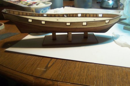
The model on its stand and it does support the model better with the four support posts.

Photo_06 Model on Stand.JPG

Manual Page 30 of instructions: Davits installation; Davit supports, 'Anchor Davits, and Life boat Davits.

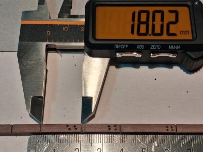
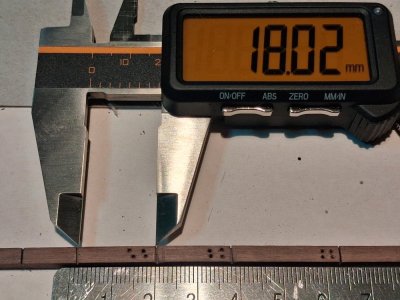
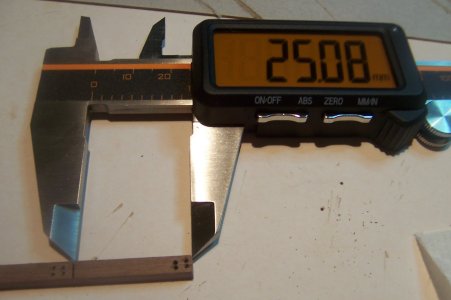
This step will involve using up the remainder of the 4 x 4 mm stock for the Part #37 Davit supports at 15 mm, but the actual measurement is only around 12 mm, Part #38 davits at 18 mm, and Part #39 the Life Boat Davits at 25 mm. 'Anchor Davits will be installed in the bow section of the model of course and will need the Davit support, but the life boat Davits will just be glued onto the Stern Gallant Railing, with a little rounding sanding at the end to make it more clean looking.

A photo of the 4 x 4 mm board marked for cutting and starter holes drilled into the and Life Boat Davits, length of 18 and 26 mm. respectively.

Photo_07 all davits.jpg
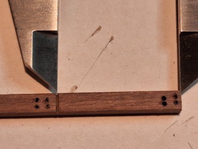
A closeup of the first Life Boat Davit, (at 25 mm length), to be installed on the stern Gallant Railings with the four starter holes drilled.

Photo_09 Closeup of Anchor Davits.jpg
Closeup of the Ancho Davit at 18 mm. with starter holes drilled into it.

Photo_09 Closeup of Anchor Davits.jpg

Closeup of the Life Boat Davit at 25 mm. with starter holes drilled into it.

Photo_10_Life Boat Davit.JPG

I will gently cut these pieces and square all of the ends off ready to be worked a bit and then glued onto the Gallant Railings.

Comming up will be installing the channels and pinrails.

Thanks for checking in, until next time.

Photo_08 Closeup of Life Boat Davits.jpg
 
Last edited:
Back
Top