• Ships of Scale has incorportated an extra level of security when you log In. Please follow on-screen prompts to acknowledge that you are not a robot via a "Check Box" or a "Pictorial Check Box Puzzle". This is needed due to higher level of AI Activity Security.
  • SUBSCRIBE TO SHIPS IN SCALE TODAY!

    The beloved Ships in Scale Magazine is back and charting a new course for 2026!
    Discover new skills, new techniques, and new inspirations in every issue.

    NOTE THAT OUR NEXT ISSUE WILL BE July/August 2026
  • Win a Free Custom Engraved Brass Coin!!!
    As a way to introduce our brass coins to the community, we will raffle off a free coin during the month of August. Follow link ABOVE for instructions for entering.

Albatross by CharlesEdward – Constructo - 1/55 –

This is La Toulonnaise, a quite similar French schoner. It shows a single crosstree at the aft main and a double at the fore mast, with the longest of them at the aft end. I don't say you plans are "wrong", but somewhat unusual. A crosstree acts as a spreader for the topmast rigging. So if no shroud passes through it, then what would be the use of it?
1791056463812.jpeg
 
Last edited:
Thank you for commenting and being patient with teaching me about this crosstree detail as I am always open to learning more about the sailing vessels of the 14th to 18th century, which is my interest.

You make a good case, and I totally understand and appreciate the plan drawing you included for me to study. The Constructo Albatross is very different from the OcCre Albatross, that I am in the process of doing also. Quality of the OcCre is far better than the Constructo kit, I bought both of the kits almost at the same time with the purpose of comparing the quality and materials of the two very different priced model kits. Although the OcCre was on sale when I bought it from Model Expo, the original price of that kit was like doubled or more from the Constructo kit. The OcCre kit is a tad more complictated than the Constructo kit, but it has been fun having a more simple model than the Montanes is to work on for a bit.

I studied the my plans more and only the two forward shrouds 'wrap' around the Main crosstree, the third / aft one goes all the way to the top of the upper main mast and I am thinking of drilling a small hole where the plans show the wrap to be just for ease of running that aft shroud through, since I am currently installing all of the blocks and eyebolts and etc. for the two masts now. The foremast shrouds are very similar in that the four forward shrouds wrap through the crosstree, while the aft one goes to the top of the upper foremast also, so probably do the same small rigging hole in the upper foremast.

I believe the OcCre Montanes build tha I am doing and posting here also, shows what you are saying in the foremast crosstrees that are actually above the mast platform on that model which has a Royal mast for each of the three masts, Fore, Main, and Mizzen. I have only completed the Foremast on the Montanes, those pictures are posted on this website. The crosstrees there did not have such a pronouced differned in the crosstree bases that this Albatross kit has.

So much to learn still before I actively continue that Euromodel Royal William mode, just spent some time checking all of the wood stock again because when I first opened that complicated expert / master kit I did the main hull assembly and the first and second battery decks and carved two of the channels, which I had actually forgotten which model they were for. For some weird reason I cut the Foremast Channel in three pieces, I do NOT know why though, I may have to rebuild those from scratch once I start on that one again.
 
October 7, 2026

Manual Page 60 of instructions: Installation of all the Rigging details for both masts BEFORE installation onto the model.

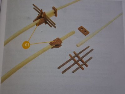
Parts #78 – the thin black thread, Part #81 - a double sheave block, Part #82 – Eye-bolts, #103 through #105, and finally #116; 103 is the precut cheeks in parts pack #8, four parts 104 are the 8 mm rings in parts pack #9, 105 is single-sheave blocks in parts pack #10, 116 is the final 0.25 wire found in parts pack #12 for mast straps.

From the instruction manual, without counting the crosstree pieces there are six parts per mast; lower and upper main mast, lower and upper foremast, 2 Cheeks per mast, and the 2 pre-cut caps, with two 2 mm holes drilled. I had to slowly enlarge both openings to fit the tapered tops of each mast part.

Photo_01.jpg

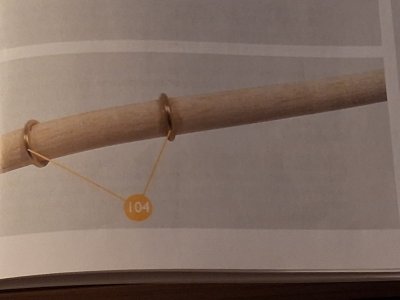
From the instruction manual the position of the mast rings represent mastheads and partners.

Photo_02.jpg

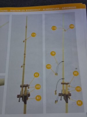
From the instruction manual details of the rigging blocks and wires and thread to connect them to the actual masts. I had to reference this and the plan sheet many times to get the blocks set correctly.

Photo_03.jpg

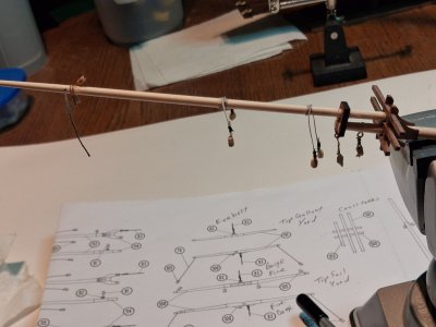
My mainmast completed rigging installation, I tried using the thin wires to attach the single blocks located on the upper masts, worked okay but took some time with each one. All the blocks are a single sheave except for the lowest block, which is the only double sheave block on this mast, which looks like it will hold the main mast boom in place when that is installed.

Photo_04.jpg

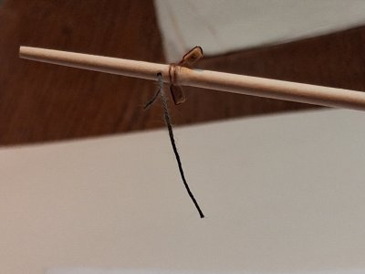
I did drill a small 1.5 mm hole in the upper main mast just above the highest single block to thread the abaft shroud through for easier installation of the mast, which is coming up soon.

PHoto_05.jpg

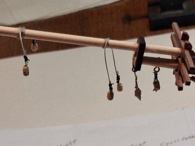
A closeup of the all of the lower rigging tackle on the main mast. One big difference between the main and fore mast is that the main mast uses more thread to attach the sling lines while the foremast uses short wires to do the same.

Photo_06.jpg

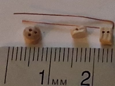
The typical block and tackle for this mast is shown below, the single sheave block and the wire used as the connector to the eyebolts to install onto the masts.
I have some family members checking in every so often, so this photo is to help them, and others reference exactly how small the included deadeyes, single sheave block and double sheave block are, and the wire I use to connect them usually to the model.

Photo_07.jpg

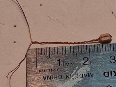
The Foremast upper single block and tackle used to install these parts onto the Foremast, to hold the Yards, booms and gaffs.

Photo_08.jpg

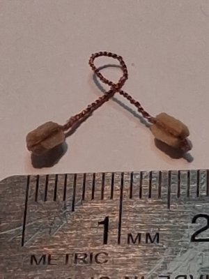
This next photo is of the above assembled block and tackle ready to be wrapped around the upper foremast.

Photo_09.jpg

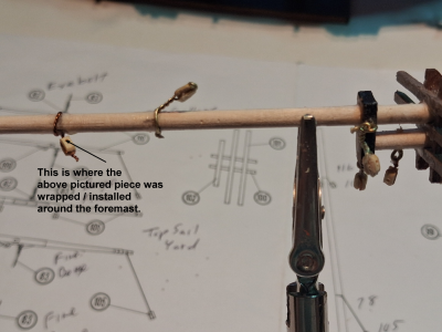
This next photo shows where the above pictured piece was installed on the Foremast, which completes all the tackle required by the instructions on the Mainmast and Foremast. One big difference between the main and fore mast is that the main mast uses more thread to attach the sling lines while the foremast uses small wires to do the same thing.
Photo_10 Comments.png

Next up we continue to Manual Page 62 of instructions: Assembly of the Foremast Yards, and Installation of the Rigging details for all three yards before installation onto the Foremast and model.

Thanks for checking in, until next time.
 
October 9, 2026

Manual Page 62 of instructions: Assembly of the Foremast Yards, and Installation of the Rigging details for all three yards before installation onto the Foremast and model. I made an Excel Spread Sheet for the size, (diameter, length and taper diameter); a summary extract for these parts follows: #106 tapered to 4 mm, 108, and #110 tapered to 1.5 mm.

Includes Parts #78 – black thread, 82 – Eye-bolt, 83 – thin beige thread, and #105 – Single blocks through #110; 106 is the foreyard, one part 107 is 2 x 2 x 20 foreyard cleat, 108 is the topsail yard, two parts 109 are from 2 x 2 x 15 stock making the topsail yard cleat and the top gallant yard cleat, 110 is the top gallant yard.

The photo below shows my un-tapered parts #106, 108, and 110.
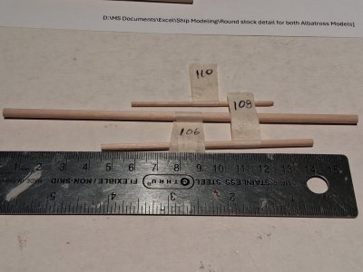
Photo_01.jpg

From the instruction manual for reference shows how the three yards should be rigged before attaching to the foremast. All the blocks shown are part #105, single sheave block, each yard has an eyebolt installed to actually attach it to the foremast via a small line. The small trailing line shown on the lower foreyard wooden cleat (bottom of photo) is the parrel line used to hold the yards onto the mast with freedom of movement to adjust to wind conditions and the raising and lowering the sails.
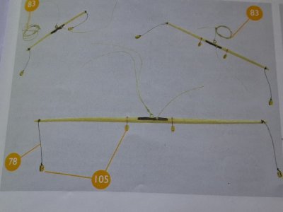
Photo_02.jpg

The below photo from the instruction manual shows the three steps for shaping the cleats, from bottom to top, glue the 2x 2 cut piece #109 , (either 10 mm. in length – two pieces; or the one 20 mm. length), to the middle of the yard, sand the round hole to accommodate the mast, and finally sand the pieces to the shape shown in the top piece and do not forget to drill the two small holes for the parrel lines, (hard to see in this photo). I sanded a small flat surface onto the middle of the yard to accommodate the cut cleats for white glue setting.
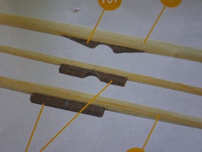
Photo_03.jpg

A more detailed view of one of the finished yard cleats with the seized sling (?) line on the eyebolt ready to hold the yard up and the parrel line to clasp the yard to the mast.
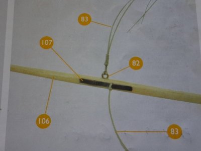
Photo_04.jpg

My first step in attaching my wooden cleats to the foremast yards, (main yard, topsail yard, and top gallant yard).
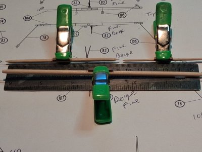
Photo_05.jpg

I filed and shaved and drilled so that the wooden cleats looked pretty good and matched the instruction photo, than I went and broke the topsail yard cleat while drilling the small parrel line holes and had to use superglue to repair it, (this was before I found the several #75 - #80 bits). I got it to work, somewhat, but it ain't pretty, let me tell you that now. The remaing two yards, topsail and top gallant yards, will be shown in the next posts.

The main foremast yard is shown below with all tackle attached, ready for securing to the Foremast. This one looks real good, compared to the broken topsail yard.
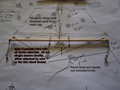
Photo_06.png
Another photo of the foreyard is shown below on the rig I used to attach all of the tackle. Note that the Eyebolt for the slings is on top here.
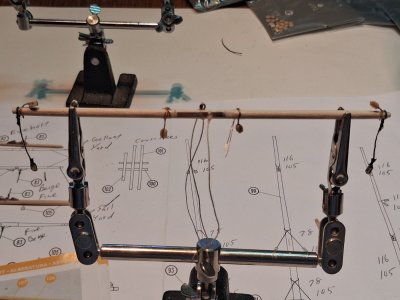
Photo_07.jpg

A closeup photo of the middle section of the foremast yard showing the eyebolt and a couple of blocks being installed, the right one is drying before I twist it up more.
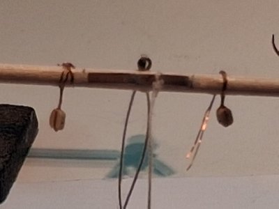
Photo_08.jpg

Another photo of the foreyard is shown below on the rig I used to attach all of the tackle. I rotated the yard 90 degrees so that now you are looking directly at the sling Eyebolt, for a different perspective of the piece, plus you can see finished wooden cleat that came out pretty darn good.
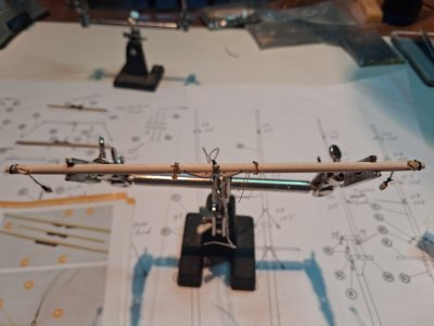
Photo_09.jpg

Just hanging around here as I wanted to see how I could attach all of the yards to the foremast, as Mastini suggests in his book and the instructions replicate.
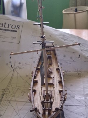
Photo_10.jpg

Next up Manual Page 64 of instructions: Assembly of the Foremast Spanker Boom, Mainmast Boom and Gaffs, and Installation of the Rigging details for all booms and gaffs before installation onto the masts and model.

Thanks for checking in, until next time.

 
Back
Top