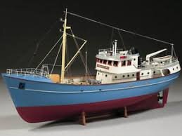
Mary Ann by Billing Boats 472 - Build log

Joined
Sep 3, 2021
Messages
32
Points
48

Location
Lake Macquarie, NSW, Australia
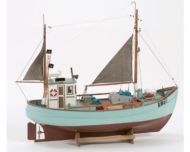
Hi, I’m building Billing Boats Mary Ann (kit no. 472). This kit is rated as ‘Advanced Beginner’ by Billing and I think that’s probably a reasonable description of my skills as this is my first boat build, but I’ve been building planes from balsa, and other kits, on an occasional basis for more than 50 years. I haven’t seen too many build logs of Mary Ann, particularly with the additions I’m planning to make, so I thought that this might be useful to others setting out on a similar path. I’m planning on putting up plenty of photos and describing what worked for me and what I’ve found needed changing from the kit. (Please let me know if it gets to be too much)

I like ‘working boats’, preferably from the first half of the 20th century, so this trawler with its nicely rounded stern and its generally solid proportions has much appeal. As a first build, I was also looking for something that wasn’t too big (550mm long, 430mm high, 1/33 scale) and needed to be planked (a skill I’d like to develop). To add to the challenge, I plan to turn this static model into a working RC model and add some lighting.

I had to look around for some time just to get my hands on the kit in Australia, and I ended up buying it online from NZ and shipped it over.

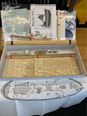
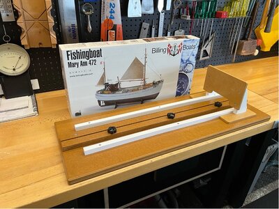
So, here is what the kit looks like in the box…
1708587507353.jpeg

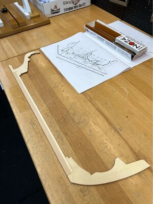
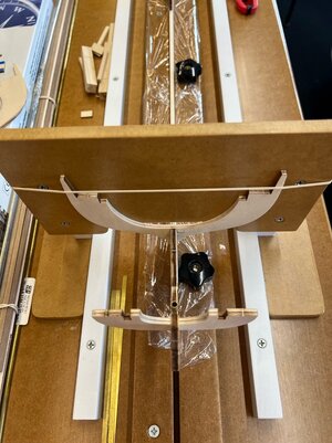
While waiting for the kit, I built a building jig as shown above, out of some leftover MDF I had in the workshop.
 
Opening the box, here’s what you get…

1708587697434.jpeg

The overall quality of the components and timber was a pleasant surprise. The laser cut sheets are all very well done, the fittings are good quality and are almost all machined brass or plastic. The kit comes with one large full-scale drawing with plan and side elevation profiles, and a 30-page booklet that I hesitate to call an instruction manual. If you are looking for a model that provides step-by-step instructions, then this one is not for you. There are 5 or 6 paragraphs of basic direction and then a range of drawings that show sections of the build and the part numbers and colours to paint.

I’m writing this a few weeks into the build, so I’ll add that one thing to watch out for…is in areas where there are multiple drawings of the same area (or when comparing the booklet drawings to the full-scale sheet) there is often some disagreement between them around dimensions. I also found the bill-of-materials reference numbers to the plan were incorrect in a few places. Not a huge issue, but keep an eye on it.

Using common sense, the drawings are generally more than sufficient, particularly when you also consult the full set of photos of the model that Billing hosts on a Google Drive. These are high resolution photos of what looks like the model shown on the box cover, from many angles, and they help to fill in your understanding of what you are trying to build. Here’s a link https://photos.google.com/share/AF1...?key=ZEdEQWZwMWRzUWg4VWdSTmh3YWJ2OVl4ampING1B

That's enough talking about it, time to start building, the next post will be laying the keel…
 
The laser-cut parts come out cleanly and the ply and strip timber are all clear of imperfections. I’ll be using Titebond 3 for gluing the keel and bulkheads.

1708588039816.jpeg

After assembling the keel, I put it in the jig and started to lay out the bulkheads, and then I thought…given I’m planning to add RC components, I really should start thinking about the mechanical side of this before I go too far. I have to work out a few things like…the positioning of the prop shaft, where I’m going to fit an electric motor & batteries, do I have enough room for a steering servo, and other componentry. Remember, this kit is designed as a static model and has no hints for converting it to RC.

I have found one other example, on the internet, of this kit being converted to RC, by Bob Vaughan of Luton & District Model Boat Club. Although there is no description of Bob’s build, there is an excellent set of photos of the build at all stages. It is a beautiful build and I have spent a fair bit of time looking at how he integrated the drivetrain into the hull. https://lutonmodelboat.co.uk/Building-Mary-Ann.html

That's all for today, plenty more to follow.
 
I wish you a lot of fun with this project :cool:
 
Working out where the prop shaft / motor will go…and what to buy.
As a novice, one of the things that I’ve struggled with a little, is how to work out the size of the shaft and motor to use in this model (given there are no instructions for this). I’m sure this becomes second nature after you’ve worked with boats for a few years. I figured that the safe way to proceed was to start the build, then be able to see the area, and work out what might work. Hence, I haven’t pre-purchased the shaft and motor.

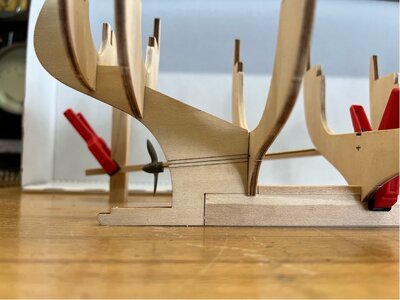
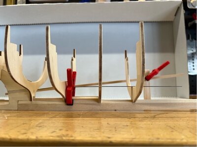
My first step was to setup the keel and bulkheads (with no glue) so that I could gauge the angle and path of the shaft, and the likely position of the motor so that I can work out the shaft length and motor size.

1708659928656.jpeg
In the shot above, I have the kit’s plastic prop on a piece of brass rod (through a block that you can’t see) to get an idea of angles. In the background there us a piece of 4x4mm timber pegged to some uprights so I could extend that further through the body of the hull. I’ve pencilled in the position of the stern tube on the stern post and also marked a cross on the right-hand bulkhead where I will need to drill a hole for the shaft. From that point onward there is a reasonable amount of room to play with.

1708659984970.jpeg
The thin steel rule, to the right of the clamp, is sitting on the floor of the bulkheads, showing that they drop down in height after the two that will need a hole for the shaft to pass through. In the plan, the deckhouse sits above this area, so is likely to be the place for the engine mount, shaft coupling etc, so I can get access.

One thing that is evident is that I’ll have to stop the build of the hull, as I can see that I will not be able to just drill a hole in the stern and slip the shaft into the build. This kit’s keel and stern post are only 4mm ply and the shaft outer tube is likely to be 5-6mm outside diameter, so I’m going to have to completely cut the stern post and epoxy the shaft tube into the stern post as shown in the pencil marks above. This will be much easier to do while the keel and stern post can be laid flat. It appears that this is also what Bob Vaughan did (mentioned in an earlier post).

Again, due to my lack of experience, I’ve decided to spend a little extra and buy a known brand (Raboesch) as I know they can be shortened, seem to have a good reputation and I think it reduces my risk. So, after looking up my options, I’ve decided on a 300-04 shaft (27cm long, 3mm shaft, M3 prop thread, 6mm OD of the shaft case) and a 3 blade 35mm LH brass propeller. The shaft is way longer than I need, but I can cut that down. The kit’s plastic 2 blade prop is 35mm, but I like the look of a 3 blade. I’m planning on using an MFA Como motor (457RE385LN), it’s a 385 Low Noise…higher torque, lower revs which seems appropriate for a working boat that I only expect to motor around at something just over what would be expected as a scale speed.

Note: this part of the log was written early last month, so I’m doing this part of the build during January and the only specialist model boat supply shop (that I can find) in Australia that sells brass prop shafts and brass props is on holidays until the end of Jan, so I’ll move onto other parts of the build for the moment.
 
While I await the prop shaft/prop/motor, I'll move on to the rudder...

Replacing the Rudder
The kit, as supplied, has a simple wooden rudder with a wooden dowel rudder post…it’s a static model and that’s all that you would require. But I’m going to RC this build, so I think it would be wise to fabricate a rudder from brass sheet and hang it on brass rod. I plan to use slip-fit brass tubing as a bush at the top and bottom. The top tube will be greased before installation to aid with friction and reduce the likelihood of water intrusion.

The standard kit has the bottom of its wooden dowel post sitting in a hole in the 4mm ply keel mentioned earlier. I don’t think that would be a long-term solution in this case (given it will be going in the water occasionally), so I’m going to shorten the timber rear extension of the keel and make up a brass section that will be screwed to the keel and have a bush to accept the new brass rod rudder post.

For the rudder blade, I purchased some 0.25mm K&S brass sheet. It’s thin, but I don’t have much tooling for working with metal sheet, so I needed something that would be easy to work into the required shape. As it turns out, I decided on a design that matches the original profile but wraps around the post and will be epoxy glued/filled, so it will be plenty strong and probably more hydrodynamic than the original.

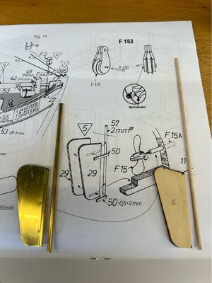
Here is the original and the start of its replacement…

1708660317803.jpeg

That’s a reasonable start, but now I need to make up some narrow brass strip to make the lower bearing support (keel extension) and the rudder straps. Although I like metalwork, it’s not something I have much experience with and cutting long strips from thin sheet is something that had eluded me. I had tried various snips (they always deform the strip), people have suggested a Dremel with rotary metal cutting blade (I can’t see that working well over any distance), or buy it ready cut (well, yes if you can source it in the width required). No, I think it’s time to work out how to do this repeatably.
 
Cutting brass sheet into strip…
For those of you who know what you’re doing, sorry if this next bit is a bit of a lesson in the basics…but I found it useful, and it might be handy for beginners.

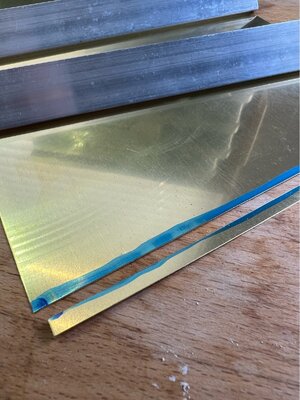
A little Googling and some YouTube watching, and it seems that for scale modelling at least, with a bit of care you can simply ‘score and snap’ brass sheet. Well, I was sceptical, but I went out to the workshop and found a good length of 3mm thick aluminium right-angle (25x25mm) and made a couple of ‘breaker bars’ about 250mm long. Then using the 0.25mm thick sheet, I scored a line to create a 4mm wide strip (a used a Stanley knife with a segmented blade) and ran it across the sheet about 5 times and then put the sheet and the breaker bars in my vice and, with the right technique, it breaks easily and very cleanly.

The photo below is after breaking, but before any dressing of the edges. The aluminium strips sitting on the sheet are the breaker bars…

1708660591729.jpeg

The edge on the new strip and original sheet are both flat and just need a simple clean up with a file or emery. I can repeatably create strips as fine as 2mm wide from the 0.25mm sheet (used in a future post), and I’ve since cut several 4mm strips from some 0.5mm thick sheet to use as a guard under the keel. This might seem like a simple technique to get excited about, but it has filled a gap in my knowledge and taken the stress out of creating brass strip.

I have more notes and photos on this if people are interested.
 
Rudder upper & lower fixing points
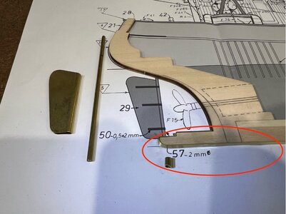
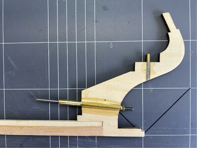
Back to the building…here the 4mm wide x 0.25mm brass strip has been bent to fit the shape of the lower rear of the keel and a section of tube has been cut to use as the lower bush (red circled area). This is being done because I don't want to have the brass rod sitting in a ply timber hole, and I also want a way to be able to remove the rudder from outside the hull.

1708752415293.jpeg

The rear 8mm or so of the keel extension will be removed to allow room for the new bush. The top of the brass strip was drilled to size, and I’m going to use 2-part epoxy to glue the bush into the strip and fill the area behind at the same time. For me, the strip is too thin to braze, and I don’t know if soft soldering would be any stronger than 24hr cure epoxy. After curing, the epoxy was sanded back to the dimensions of the strip.

That has sorted the bottom mount, now to the rudder upper bush. This is simply a section of K&S brass tube. The rudder post is solid 3mm K&S brass rod, and theoretically that should give a sliding fit in their 3.5mm tube, but I don’t have any in stock. I do have 5/32” tube, which it slightly larger, but it gives a nice sliding fit when greased and is less likely to bind if I get a bit of grit in there. Due to the tube OD and the stern post being similar thickness, I had to cut the ply stern post and remove a 4mm section, so that I could epoxy glue the almost 4mm OD tube in its place.

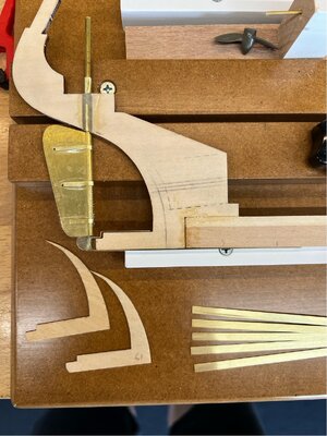
Here's a photo with everything almost finished. The lower strip will be secured to the keel using very small 304 SS screws (M1 x 10mm…it’s amazing that you can buy just about anything on the internet, and for next to nothing if you're willing to wait for it). This will allow me to remove the lower fixing point, if needed, and then drop out the rudder & its post

1708752730538.jpeg.

The photo above also shows the 2mm brass strips, that I cut using the earlier technique, used as the straps around the rudder blade and also the 4mm strips of thicker sheet that have been cut to fit along under the keel for protection.

Installation of the prop shaft also requires a cut the stern post, in a similar way to that used above, I'll tackle that in the next posting...

Pete
 
Hi Pete. I am thoroughly enjoying your build log. It is obvious that a lot of planning has gone and is still going to the build, which is something I always appreciate. I think your brass rudder looks excellent along with all the assorted bits and pieces.
 
As I mentioned earlier, the hull was started a few weeks ago and I had to suspend the build at this point while I waited on the prop shaft, prop and motor (I moved on to the deckhouse). But in real time, I now have those bits, and I think the log will make more sense if I rearrange the timeline so that I can continue with the hull (which is underway as I write this) and I’ll go back to the completed deckhouse later.

Drivetrain
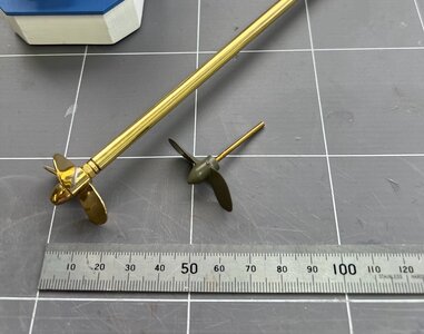
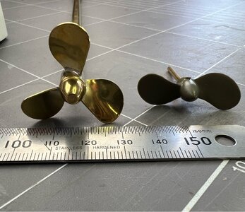
A big delivery today…the prop shaft, prop and motor (along with other goodies). Here’s a comparison between the new & original props.

1708820704652.jpeg

I bought a shaft that is much longer than I’ll need (27cm), but it can be shortened and is nicely made gear compared to the supplied plastic prop and dummy shaft. The shaft is a Raboesch 300-04 (6mm OD, 3mm shaft with M3 prop thread).

1708820750718.jpeg

Both propellers are 35mm diameter, the new one is a Raboesch 146-12A (35-L-3bl-M3). It will be powered by an MFA Como Drills 385 5 pole, noise attenuated motor (457RE385LN). I’m adding the part numbers because I know it would have helped me in the research stage.

1708820828877.jpeg

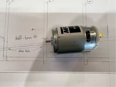
The motor comes with a folded steel mount with 4 x 3mm holes for mounting. It is a modest sized motor, but it is only a relatively small boat. Specs are … Brushed, 6 - 12V, max efficiency at 5950 rpm & 0.9 amps, stall current 5 amps, stall torque 660 g-cm, weight 110g, turns anti-clockwise with red to positive. I have a set of Raboesch shaft couplings to suit, but I and also bought a piece of flexible tube. Testing it on the bench using a DC power supply, I found the flexible coupling worked very well, and given the low torque application I'm going to run with that...its also a lot more compact.

I plan to run the motor on LiPo cells, not sure yet whether to go with 2S or 3S, I’ll do a bit of testing. I’ll be using a HobbyWing Quicrun 1060 ESC, overkill for this application, but it won’t hurt.

Pete
 
Welcome aboard Pete :)
good luck with the Mary Ann. Enjoy the build. I will keep following with great curiosity
 
Hi, I’m building Billing Boats Mary Ann (kit no. 472). This kit is rated as ‘Advanced Beginner’ by Billing and I think that’s probably a reasonable description of my skills as this is my first boat build, but I’ve been building planes from balsa, and other kits, on an occasional basis for more than 50 years. I haven’t seen too many build logs of Mary Ann, particularly with the additions I’m planning to make, so I thought that this might be useful to others setting out on a similar path. I’m planning on putting up plenty of photos and describing what worked for me and what I’ve found needed changing from the kit. (Please let me know if it gets to be too much)

I like ‘working boats’, preferably from the first half of the 20th century, so this trawler with its nicely rounded stern and its generally solid proportions has much appeal. As a first build, I was also looking for something that wasn’t too big (550mm long, 430mm high, 1/33 scale) and needed to be planked (a skill I’d like to develop). To add to the challenge, I plan to turn this static model into a working RC model and add some lighting.

I had to look around for some time just to get my hands on the kit in Australia, and I ended up buying it online from NZ and shipping it over.

So, here is what the kit looks like in the box…

View attachment 429632

While waiting for the kit, I built a building jig as shown above, out of some leftover MDF I had in the workshop.
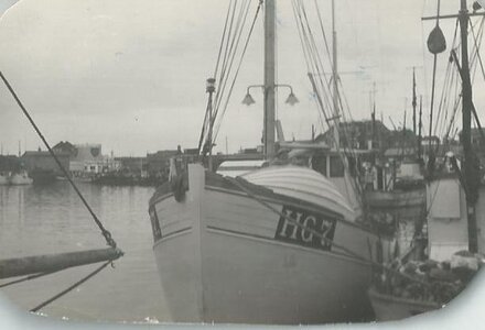
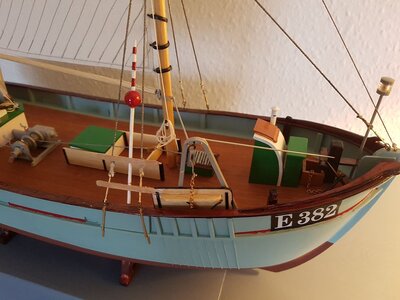
I built this model back in 1960. An easy model to build. This model is matriculated in Esbjerg E, I had 4 uncles each one had this fishing cutter -all built of wood and in Denmark. They were real cutters from Hirthals HG.Denmark- Hg 6, HG 7; Hg 20 and HG 120. The main difference with these Danish build cutters.- The hulls were built after the same drawings - were the tools for different fishing methods. I have a lot of info. about that, as I was brought up here for about 10 years. If you need info. just ask.
Yes it can be built for MC and with both navigation light, cabin and wheels housenorden_cutter_lg.jpgNORDKAP 1.jpgHG 7 HAVORNEN.jpg439634_03.jpg439634_11.jpgDANA-esbjerg kutter.jpg89328167_10158594421226189_1141178806321545216_o.jpg89587154_10158594420826189_4360205267950895104_o.jpg90884411_2662910817274332_2949206153554296832_o.jpgKRABBEN KUTTER 7.jpg

BACTE.jpg
 
I built this model back in 1960. An easy model to build. This model is matriculated in Esbjerg E, I had 4 uncles each one had this fishing cutter -all built of wood and in Denmark. They were real cutters from Hirthals HG.Denmark- Hg 6, HG 7; Hg 20 and HG 120. The main difference with these Danish build cutters.- The hulls were built after the same drawings - were the tools for different fishing methods. I have a lot of info. about that, as I was brought up here for about 10 years. If you need info. just ask.
Yes it can be built for MC and with both navigation light, cabin and wheels houseView attachment 430646View attachment 430647View attachment 430648View attachment 430649View attachment 430650View attachment 430651View attachment 430652View attachment 430653View attachment 430654View attachment 430656

View attachment 430655
Hi El Capi,
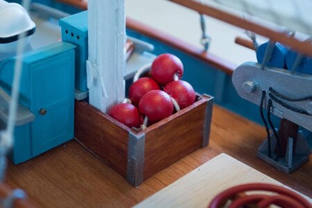
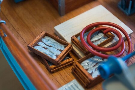
Great looking model, I'll be very happy if I finish with something as good. I particularly like the carved fish in the boxes on deck...nice touch.

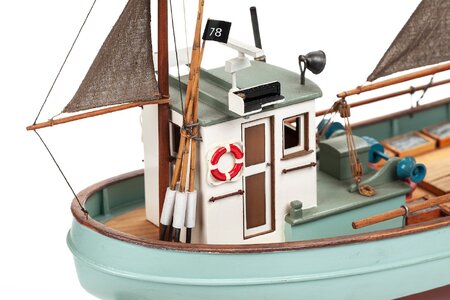
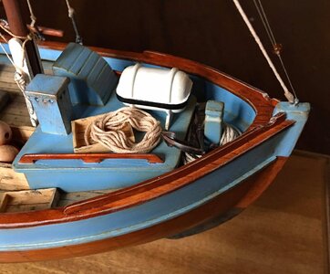
Given your knowledge of this type of boat, I do have a question for you...in the version that I'm building, there is a door on the rear wall of the wheel house (it's not in the version that you have built). I'm wondering if you know what it was for?...I can only guess it was for access to the under-deck area, as the bottom of this door is at deck level rather than at the raised floor of the wheel house. Did they store nets, or maybe chilled the fish, below decks?

Thanks for the background information.
 
Mounting the propeller shaft
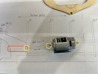
After drawing it up, and also consulting the photos of Bob Vaughan’s build, I decided to mount the motor between bulkheads 6 & 7. This means the shaft comes through the stern post and is terminated in the first internal space between bulkheads 7 & 8. So, after buying a 27cm shaft, I’m going to cut nearly two thirds off…the leftovers will go in the appropriate spare parts bins for future use.

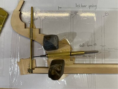
The mounting requires the stern post to be severed and a 6mm slot removed from its 4mm thick body. That latter dimension was what ruled out drilling a hole and pushing the shaft tube through from outside. The shaft will be epoxy glued to the two parts of the stern post and it is important that the alignment of this works for the rest of the hull. To this end, I ended up drawing the elevation at full size on paper to allow me to align everything over the drawing while doing the glue-up.

Here is the drawing, without the keel laid over it, so you can see what is happening. The pencil lines under the red outline is where the stern post will be cut, and the yellow circles are holes that need to be cut in the two bulkheads (7 & 8). There is also a change to bulkhead 6 (under the motor) that is shown in a later photo.

1708910576392.jpeg

And below is the set-up, with epoxy applied. I’ve taped cling wrap over the plan so nothing sticks to it. Underneath the stern post and the keel, in a number of places, there are 1mm thick spacers lifting the 4mm stern post off the surface (the shaft is 6mm OD, so the stern post centreline needed to be lifted a millimetre to keep the shaft aligned). The two parts of the cut post have been weighted with lead to keep everything stable for 24 hr. You can’t see it, but underneath the epoxied section I have placed some clear tape to form a nice curved mould underneath so that I won’t need to do too much finishing of the epoxy surface…unfortunately that wasn’t practical to do to the top surface as well.

1708910664579.jpeg

Here it is (below) after curing and cleaning up. The epoxy section on this side of the keel (that's underneath of the photo above) did not need any clean-up due to the tape moulding mentioned above. The other side was cleaned up with one of those 10mm Dremel drum sanding rolls.

1708910734480.jpeg

Now that all of the cutting and gluing of the stern post is complete, next time we'll be back to building in the jig.
 
Hi El Capi,
Great looking model, I'll be very happy if I finish with something as good. I particularly like the carved fish in the boxes on deck...nice touch.

Given your knowledge of this type of boat, I do have a question for you...in the version that I'm building, there is a door on the rear wall of the wheel house (it's not in the version that you have built). I'm wondering if you know what it was for?...I can only guess it was for access to the under-deck area, as the bottom of this door is at deck level rather than at the raised floor of the wheel house. Did they store nets, or maybe chilled the fish, below decks?

Thanks for the background information.
Hi No this is the access down to the Engine, which in all this type of cutters were just under the wheelhouse.
Another important thing I forgot to inform you: All these cutters from 20- to 30 tonnages had general a crew of 3 or 4, where none were mechanic engineers, therefore this type of cutters WERE required to have full SAils and its Riggen, so it problems with engine, you said the sails -if not set already -as mane has the sails set, except in harbour
.in the Google under Danish fishing cutters (in Danisk Kutter ) there is a huge of images, apart amount from what I have.
have fun with the build -you can make more than one with the same hull depending on which type of catch of fish, with radar or without, and other electronic devices on the wheelhouse roof. winches can change too- forward or sideward etc.
 
Bulkheads
Don’t worry, I won’t bore you with a blow-by-blow gluing of the bulkheads…but I will add a small warning for new players in this area. I have a jig that makes it very easy to align things vertically (perpendicular to the base), and also across the model (perpendicular to the length of the keel) and that lulled me into a false sense of security. On the first couple of frames, I didn’t check the height of each side once it was in the jig to make sure that it was aligned evenly on either side of the boat. This resulted in a 1-2mm side difference…doesn’t sound much (and you can’t see it in the photo below), but on a small model it’s enough to be noticeable when you start connecting other members of the structure. I also didn’t find this until after I had put all sorts of additional strengthening in the area, so I will fix it with sanding and additional filling as needed. Lesson learned, and all the others were measured from their tips to the jig floor, to ensure they are aligned as you’d hope.

1709098915317.jpeg

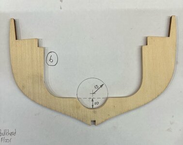
I mentioned earlier that bulkheads 7 and 8 will need to be drilled to allow the prop shaft 6mm OD to come through. They are fairly simple to work out where the 8mm hole needs to go. Bulkhead 6 also needs a modification as the motor case is fairly long for its size and I preferred to have it sitting back from the hole in 7 so that I’d have room to play when fitting the coupling to the shaft. The photo below shows the cut-out and its dimensions. I used an Aussie 20 cent coin as a template.

1709098969369.jpeg

Next time we’ll work on the motor mount.
 
Back
Top