THIS IMAGE IS TAKING OF ME AS THE "SKIPPER" ON A SHIP LIKE YOURS. IT SOME THE VOLOTER NAVY RESERVE-ONE AFTERNOON EVERY WEEK AND ONE LONG TRIP EVERY 4 WEEKS (FROM FRIDAY AFTERNOON UNTIL MONDAY MORNING. IT WAS A COÑD DAY WITH THIN ICE IN THE WATER. WAS ALWAYS ON THE WELL IN BAD WEATHER- GOING IN AND OUT OF HARBORS.
-

Win a Free Custom Engraved Brass Coin!!!
As a way to introduce our brass coins to the community, we will raffle off a free coin during the month of August. Follow link ABOVE for instructions for entering.
You are using an out of date browser. It may not display this or other websites correctly.
You should upgrade or use an alternative browser.
You should upgrade or use an alternative browser.
Mary Ann by Billing Boats 472 - COMPLETED
- Thread starter pete_5
- Start date
- Watchers 20
-
- Tags
- billing boats mary ann
Thanks El Capi, for the suggestion about the heated can...it's a good idea for the strips that you showed being bent (you did a nice job on those). I had already done this part of the build a few weeks ago, and I used a slightly different technique, shown below.
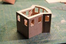
The curved front wall
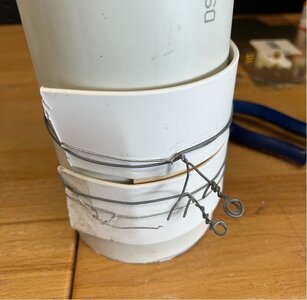
The front face of the wheelhouse is curved, and the panel is the same 2mm thick 3-ply used for the other walls, so I need to come up with a way to form that curve over a fairly large area of ply that doesn't really like to bend. In the end I found some strong PVC stormwater pipe that had a suitable diameter to form it around. The ply was then soaked for about 20 mins in hot water until I felt it had enough ‘give’ to bend without any splitting or delamination of the ply. While it was soaking, I prepared some covering to go over the ply panel - these are the slats from a PVC venetian blind (recovered when a neighbour was having a clean out) and some tie wire to put some pressure against the panel and pipe.
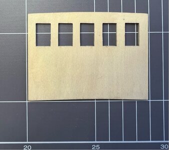
The laser cut panel was cleaned up prior to bending…
Soaked and bound to the form…
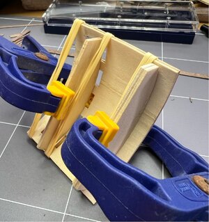
It didn’t look pretty while drying, but the next day it came out very close to what I was after. However it was still keen to relax back toward being flat so it needed to have some internal formwork to hold it to the desired curve while it dried completely. The kit comes with a single thin panel to glue in at floor level, but nothing else. They probably assume that you will glue the roof on to provide the upper support, but that doesn’t suit me, so I made up a form from residual 4mm ply from the laser cut sheets. Both of those were used to temporarily hold the curve while the final drying occurred (another day), then later glued-in in their correct locations.
Close to the final product…
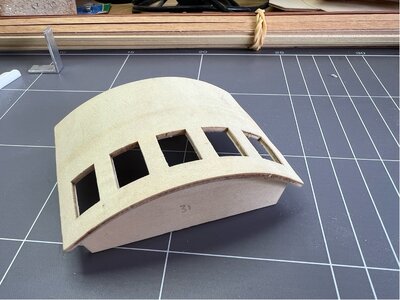
This panel was then planked and window framed to match the rest of the cabin…
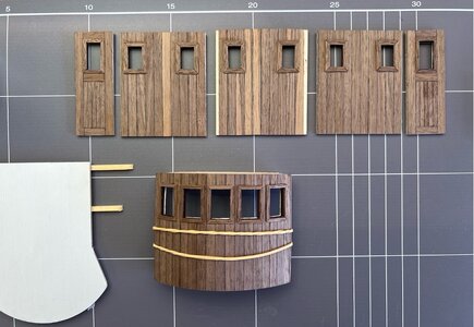
The curved front wall
The front face of the wheelhouse is curved, and the panel is the same 2mm thick 3-ply used for the other walls, so I need to come up with a way to form that curve over a fairly large area of ply that doesn't really like to bend. In the end I found some strong PVC stormwater pipe that had a suitable diameter to form it around. The ply was then soaked for about 20 mins in hot water until I felt it had enough ‘give’ to bend without any splitting or delamination of the ply. While it was soaking, I prepared some covering to go over the ply panel - these are the slats from a PVC venetian blind (recovered when a neighbour was having a clean out) and some tie wire to put some pressure against the panel and pipe.
The laser cut panel was cleaned up prior to bending…

Soaked and bound to the form…

It didn’t look pretty while drying, but the next day it came out very close to what I was after. However it was still keen to relax back toward being flat so it needed to have some internal formwork to hold it to the desired curve while it dried completely. The kit comes with a single thin panel to glue in at floor level, but nothing else. They probably assume that you will glue the roof on to provide the upper support, but that doesn’t suit me, so I made up a form from residual 4mm ply from the laser cut sheets. Both of those were used to temporarily hold the curve while the final drying occurred (another day), then later glued-in in their correct locations.

Close to the final product…

This panel was then planked and window framed to match the rest of the cabin…

GREAT WORK. YOU COULD HAVE USE HOT METHODE HEER TOO -DEPENDING OD THE SEIZE OF THE CAN. VERY WELL DONE. I CAN ONLY HOPE THAT YOU HAVE LOT OF FOLLORS. EL CAPIThanks El Capi, for the suggestion about the heated can...it's a good idea for the strips that you showed being bent (you did a nice job on those). I had already done this part of the build a few weeks ago, and I used a slightly different technique, shown below.
The curved front wall
The front face of the wheelhouse is curved, and the panel is the same 2mm thick 3-ply used for the other walls, so I need to come up with a way to form that curve over a fairly large area of ply that doesn't really like to bend. In the end I found some strong PVC stormwater pipe that had a suitable diameter to form it around. The ply was then soaked for about 20 mins in hot water until I felt it had enough ‘give’ to bend without any splitting or delamination of the ply. While it was soaking, I prepared some covering to go over the ply panel - these are the slats from a PVC venetian blind (recovered when a neighbour was having a clean out) and some tie wire to put some pressure against the panel and pipe.
The laser cut panel was cleaned up prior to bending…
View attachment 442419
Soaked and bound to the form…
View attachment 442420
It didn’t look pretty while drying, but the next day it came out very close to what I was after. However it was still keen to relax back toward being flat so it needed to have some internal formwork to hold it to the desired curve while it dried completely. The kit comes with a single thin panel to glue in at floor level, but nothing else. They probably assume that you will glue the roof on to provide the upper support, but that doesn’t suit me, so I made up a form from residual 4mm ply from the laser cut sheets. Both of those were used to temporarily hold the curve while the final drying occurred (another day), then later glued-in in their correct locations.
View attachment 442421
Close to the final product…
View attachment 442422
This panel was then planked and window framed to match the rest of the cabin…
View attachment 442423
Wheelhouse Interior Fittings
The inside of the wheelhouse has a couple of fittings in the kit. The wheel is diecast and brass plated (see below), and was pretty clean straight from the bag. This was painted to look like a timber wheel with brass reinforcing plates.
The throttle (also below) is made up from a couple of small, machined brass fittings which only needed a short piece of 1mm brass wire added and a timber support post.
To give the fascia of the dashboard a little more strength I added a semi-circle support under the lower edge, matching the upper surface, and also added a small offcut of 4mm ply behind the area where the shaft of the wheel will be mounted.
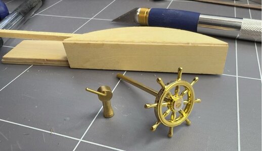
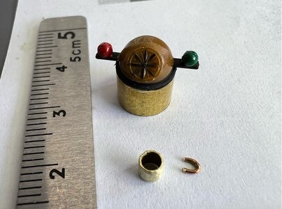
There is a binnacle made from brown plastic (an attempt to look like brass?), with correction balls and a compass face moulded on. There is no direction on how or where to mount this and I tossed up putting it on the flat top of the dashboard or give it a more traditional look with a timber post mount. I decided on the latter and added a brass tube collar to join it together and look a little more like real brass.
Now, I know that the skipper is not very productive until he’s had his cup of coffee, so I had a go at making some scale mugs. A very short length of 2.5 mm brass tube and half a link of anchor chain and it’s almost done.
Here’s the view looking forward…
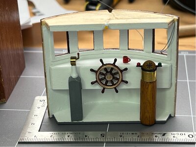
You may also see that I’ve started the wiring for some cabin lighting. A bare LED is mounted overhead, angled into the cabin. The wiring will be hidden in channels I’ve cut into the top of the upper panel and then it will run discreetly down the starboard wall into the floor. There is also an external flood light that will go up top of this wall facing forward and its wiring will run through a similar channel.
The inside of the wheelhouse has a couple of fittings in the kit. The wheel is diecast and brass plated (see below), and was pretty clean straight from the bag. This was painted to look like a timber wheel with brass reinforcing plates.
The throttle (also below) is made up from a couple of small, machined brass fittings which only needed a short piece of 1mm brass wire added and a timber support post.
To give the fascia of the dashboard a little more strength I added a semi-circle support under the lower edge, matching the upper surface, and also added a small offcut of 4mm ply behind the area where the shaft of the wheel will be mounted.

There is a binnacle made from brown plastic (an attempt to look like brass?), with correction balls and a compass face moulded on. There is no direction on how or where to mount this and I tossed up putting it on the flat top of the dashboard or give it a more traditional look with a timber post mount. I decided on the latter and added a brass tube collar to join it together and look a little more like real brass.
Now, I know that the skipper is not very productive until he’s had his cup of coffee, so I had a go at making some scale mugs. A very short length of 2.5 mm brass tube and half a link of anchor chain and it’s almost done.

Here’s the view looking forward…

You may also see that I’ve started the wiring for some cabin lighting. A bare LED is mounted overhead, angled into the cabin. The wiring will be hidden in channels I’ve cut into the top of the upper panel and then it will run discreetly down the starboard wall into the floor. There is also an external flood light that will go up top of this wall facing forward and its wiring will run through a similar channel.
The Wheelhouse Cabin
The main space inside the wheelhouse is empty as far as the kit is concerned, so I’ve added a table and will put a scale map on that before the roof goes on. The grey tube running up the back wall is a conduit for the wiring of all the rear mounted lights (2 x nav side lights, rear facing white light, and rear internal cabin light), the wiring is so fine that 8 individual wires fit through the 2mm tube.
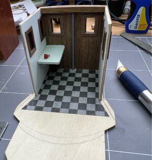
I’ve added an extra brace at the top of the rear wall, using a piece of close-grained 5mm square timber. This change to the kit is there for two reasons…I wanted something that I was confident would take the thread of a few small screws when I attach the roof (it’s slightly curved, so there is some force involved), and also as something to mount the rear cabin LED (it’s not installed in the photo).
Then to the floor. I could have just painted it grey, but I thought it might be more interesting with the chequerboard. I’ve used two shades of grey as I think black and white would make it look like a dolls house kitchen. It is just a laser printed Excel spreadsheet in plain paper that has been sprayed with clear satin acrylic. It is cut off short of the front as that gets covered by the console false floor. I don’t have any crew yet, so they will be added later. Getting very close to gluing in the doors and adding the front wall.
The main space inside the wheelhouse is empty as far as the kit is concerned, so I’ve added a table and will put a scale map on that before the roof goes on. The grey tube running up the back wall is a conduit for the wiring of all the rear mounted lights (2 x nav side lights, rear facing white light, and rear internal cabin light), the wiring is so fine that 8 individual wires fit through the 2mm tube.

I’ve added an extra brace at the top of the rear wall, using a piece of close-grained 5mm square timber. This change to the kit is there for two reasons…I wanted something that I was confident would take the thread of a few small screws when I attach the roof (it’s slightly curved, so there is some force involved), and also as something to mount the rear cabin LED (it’s not installed in the photo).
Then to the floor. I could have just painted it grey, but I thought it might be more interesting with the chequerboard. I’ve used two shades of grey as I think black and white would make it look like a dolls house kitchen. It is just a laser printed Excel spreadsheet in plain paper that has been sprayed with clear satin acrylic. It is cut off short of the front as that gets covered by the console false floor. I don’t have any crew yet, so they will be added later. Getting very close to gluing in the doors and adding the front wall.
As usual a Weel Done work -it is all going into my 1class build. have only one comment. The Trottle should be mainly on the Starboard Side, so you should change the two columns. and then generally the compass Rose in most cases was just in front of the steering wheel. god, luck and go forward as now-
a great admirer of your build. I can only hope a lot of builders will or are following you -mainly geginners, as here there is a lot to learn

a great admirer of your build. I can only hope a lot of builders will or are following you -mainly geginners, as here there is a lot to learn

for the coffee cups, you should make a square hole with diameter hole drilled in the centre, to avoid cups falling od the floor- in danish slinger grej
Hey Capi, thanks for the nice words of encouragement. I hope I'm striking a reasonable balance between giving a bit of detail to help other beginners who might decide to build this model, but not too much to bore everyone else!
And, thanks for the feedback on the position of the throttle and compass in the real boats. As it happens, I'm writing the log retrospectively, so this part of the build was done back in late Jan/Feb (just looked at the dates on the photos, wow, I can't believe it was that long ago), so I probably won't be able to change the throttle...but, as you will see in the photos of the next post, I did end up changing the compass binnacle, it now sits in front of the skipper as you suggest.
And the coffee cups...a good idea if I was building at full scale, but these ones are filled with Titebond III...it dries the colour of coffee and glues the cups to the table top, all in one go.
As you are the Captain, you do it your way, Why I am so much interested in this Mpdel us that i have built myself, and just want my time in the navy. to give your mw advice as have more than 2 years between the Fishing Cutters.Hey Capi, thanks for the nice words of encouragement. I hope I'm striking a reasonable balance between giving a bit of detail to help other beginners who might decide to build this model, but not too much to bore everyone else!
And, thanks for the feedback on the position of the throttle and compass in the real boats. As it happens, I'm writing the log retrospectively, so this part of the build was done back in late Jan/Feb (just looked at the dates on the photos, wow, I can't believe it was that long ago), so I probably won't be able to change the throttle...but, as you will see in the photos of the next post, I did end up changing the compass binnacle, it now sits in front of the skipper as you suggest.
And the coffee cups...a good idea if I was building at full scale, but these ones are filled with Titebond III...it dries the colour of coffee and glues the cups to the table top, all in one go.
In this type of cutter, there were the binnacle, compass etc Not these two columns. These were for bigger ships with one man at the wheel and to the right side the throttle and the Nacigater had the (binnacle) and gave orders to the helmsman,
I was on one of these ships in the Navy Reserve - until I left for Spain-
I will add some images of the model you are building,- only as srt before is it your build
el capo
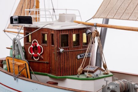
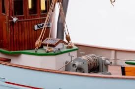
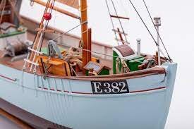
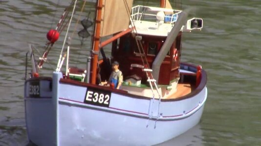
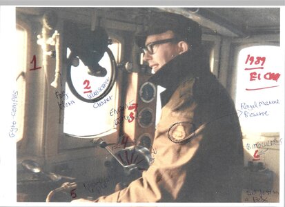
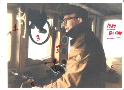
Hey El Capi, thanks for the photos, it's great to hear from someone who has personal experience with both the original vessels and is also a builder of the model itself. That photo of you with the added handwritten notes explaining where everything is in the cabin is a beauty.
Getting close to closing up…
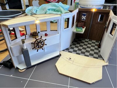
The observant will note that the compass/binnacle has been moved (up onto the dashboard) and its post removed altogether, this is because when I added the front wall, I realised that the post was sitting right in the middle of the starboard doorway and just didn’t look right. Having the compass in front of the skipper makes sense to me...and as recently pointed out by El Capi, this is where it would be on the real vessel. Unfortunately, the build has progressed too far to also move the throttle to the other side of the wheel, so I'll live with that difference.
The small hole in the bare section of the floor is to take the light wiring from the front wall into the underfloor area. You can see the interior lights working in the photo. I’ve also added a few other bits like the captain’s bag on the table (it’s actually an unusually shaped oil drum from a plastic kit), an extra coffee mug (filled with coffee), a map, and a couple of poles with hooks on the wall.
Here is it being glued together. It looks a little rough in that photo, but that’s because I did the gluing in two stages (each side, starting on the far side) so that I could true up each side separately - it had a slight twist in the front curved structure. The walls/door were also built a little long with the intention of sanding them to a consistent height once assembled.
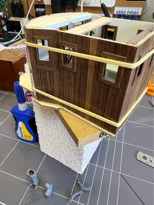

Crew
In the photo in the last post you can see the skipper being put together at the bottom of frame. I bought a plastic kit from the local hobby shop. I haven’t come across much in the way of ship’s crew in the 1/33 or similar scale. This kit is 1/35 from MiniArt and is called “German Tankers Refueling”. It has two men and a range of fuel drums. I’ll modify their hats to look less military and glue their arms at angles that suit my purposes. They are quite well moulded and after a little cleaning and gluing they look good.
Here's the skipper getting a feel for the controls…
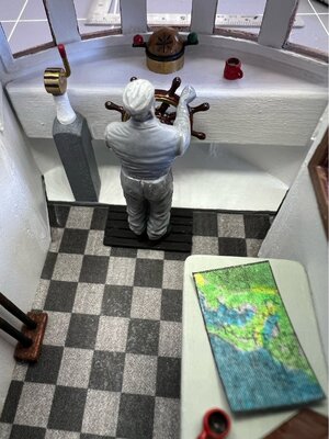
That’s a map of the NSW coast and the entrance to the Hunter River and Lake Macquarie, so he doesn’t get lost (not that he will be doing any commercial fishing in the lake these days).
I’m off to get some more paint so that I can add a little colour to his face and give him some appropriate clothing.
In the photo in the last post you can see the skipper being put together at the bottom of frame. I bought a plastic kit from the local hobby shop. I haven’t come across much in the way of ship’s crew in the 1/33 or similar scale. This kit is 1/35 from MiniArt and is called “German Tankers Refueling”. It has two men and a range of fuel drums. I’ll modify their hats to look less military and glue their arms at angles that suit my purposes. They are quite well moulded and after a little cleaning and gluing they look good.
Here's the skipper getting a feel for the controls…

That’s a map of the NSW coast and the entrance to the Hunter River and Lake Macquarie, so he doesn’t get lost (not that he will be doing any commercial fishing in the lake these days).
I’m off to get some more paint so that I can add a little colour to his face and give him some appropriate clothing.
Dressing the exterior
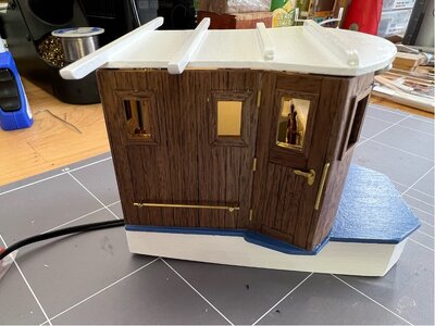
Now that the basic wheelhouse structure is together, the walls have been trued up and the sections of outside veneer panelling that were left off until the gluing was complete, have been added...it’s time to add some of the nice detailing to the doors and walls. There are no fittings supplied (or instruction given) for the door hardware, but looking at the online photos, I think a few simple door ‘hinges’ (non-functional) and a door handle and escutcheon plate will bring some life to the structure.
The hinges are 1mm brass wire, cut to length and filed to give square ends, three per door seems appropriate given the gales she might find herself in. The door handles are 1.2mm brass wire that has had the end hammered flat and then bent at right angles and filed to look like a door handle shape. The escutcheons are more of that 0.25mm brass sheet cut into 2mm strip, filed to shape and a hole added for the door handle.

It’s fiddly work (which I enjoy) and I think it looks pretty good when mounted (below)…in that photo, the roof is just sitting on the wheelhouse to hide the glare of the LEDs, hence the gaps and what looks like a poor fit. The lower grab rail does use supplied fittings…1mm brass wire through very small machined brass pins with pre-drilled holes, they work well and look good. I am going to leave all of these brass components to age naturally in the air (humid and coastal), they will be masked if I do another spray of of matt acrylic when everything is finished.
Now that the basic wheelhouse structure is together, the walls have been trued up and the sections of outside veneer panelling that were left off until the gluing was complete, have been added...it’s time to add some of the nice detailing to the doors and walls. There are no fittings supplied (or instruction given) for the door hardware, but looking at the online photos, I think a few simple door ‘hinges’ (non-functional) and a door handle and escutcheon plate will bring some life to the structure.
The hinges are 1mm brass wire, cut to length and filed to give square ends, three per door seems appropriate given the gales she might find herself in. The door handles are 1.2mm brass wire that has had the end hammered flat and then bent at right angles and filed to look like a door handle shape. The escutcheons are more of that 0.25mm brass sheet cut into 2mm strip, filed to shape and a hole added for the door handle.

It’s fiddly work (which I enjoy) and I think it looks pretty good when mounted (below)…in that photo, the roof is just sitting on the wheelhouse to hide the glare of the LEDs, hence the gaps and what looks like a poor fit. The lower grab rail does use supplied fittings…1mm brass wire through very small machined brass pins with pre-drilled holes, they work well and look good. I am going to leave all of these brass components to age naturally in the air (humid and coastal), they will be masked if I do another spray of of matt acrylic when everything is finished.

Gallows & Otter Boards
Back to building, some more deck gear to be made. The trawling gallows and otter boards. The gallows are from pre-cut 3mm ply. These were very nicely laser-cut, including the very small diameter holes. The rope blocks at the top of each gallows is made up of two cheeks of 1mm timber sheet and needs some subtle bending to then fit the machined brass single pulley. I glued up the top section first and let it dry (for a day) before then holding the cheeks in hot water to allow sufficient movement to insert the pulley and its 1mm brass wire axle…clamping it overnight to retain some bend. It works, but if I was doing it again, I would probably replace the timber cheeks with cut and bent brass sheet instead.
The tackle to hold it all together, ie the block to the gallows, is made from brass 1mm wire. I formed this around a piece of 3mm rod…about 20 tight turns while held in the vice, then used the Dremel with a cutting disc to slice along the now coiled wire, creating about 20 slightly open rings with an OD around 5mm. These are then used to make closed rings around the blocks and interconnecting with the holes in the gallows. It’s a tricky operation with two sets of needle nose pliers and, although they are ply, you still need to be careful around that top turn. I managed to break one while trying to close the formed brass ring and had to glue it back together. I’ve since found that jewellery makers use a product called Jump Rings, which are the same thing, available in various diameters and made using finer wire that looks closer to scale size.
The otter boards are fabricated from 5 x 1.8mm timber, some very fine veneer, and 1mm brass wire. Unfortunately, my kit only contained 1 of the 4 sticks of this timber stated in the material list, so I made do with some similar dimension timber I had bought for just this sort of problem (I also got extra 1mm wire because I don’t think they supply enough of that either). I glued the boards using a little white glue between the planks and then capillary CA glue to hold it all together while it dried. It worked well, the boards stayed very flat. They are finished using a Sikkens decking finish because I like the colour.
A tip for future builders...the edge veneer of the otter boards, it’s very fine timber veneer made to look like metal by painting it black…make sure that you paint the front and side of the veneer before gluing it on…it takes a very steady hand to do it afterward.
The formed wire work is fairly simple and was then CA glued to the board surface rather than drilling holes through the board as was used in the photos of the prototype.
The rigging will be added when they are added to the completed hull.
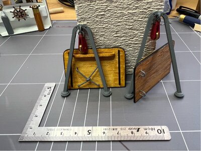
Next time I'll be adding fixtures to the roof.
Back to building, some more deck gear to be made. The trawling gallows and otter boards. The gallows are from pre-cut 3mm ply. These were very nicely laser-cut, including the very small diameter holes. The rope blocks at the top of each gallows is made up of two cheeks of 1mm timber sheet and needs some subtle bending to then fit the machined brass single pulley. I glued up the top section first and let it dry (for a day) before then holding the cheeks in hot water to allow sufficient movement to insert the pulley and its 1mm brass wire axle…clamping it overnight to retain some bend. It works, but if I was doing it again, I would probably replace the timber cheeks with cut and bent brass sheet instead.
The tackle to hold it all together, ie the block to the gallows, is made from brass 1mm wire. I formed this around a piece of 3mm rod…about 20 tight turns while held in the vice, then used the Dremel with a cutting disc to slice along the now coiled wire, creating about 20 slightly open rings with an OD around 5mm. These are then used to make closed rings around the blocks and interconnecting with the holes in the gallows. It’s a tricky operation with two sets of needle nose pliers and, although they are ply, you still need to be careful around that top turn. I managed to break one while trying to close the formed brass ring and had to glue it back together. I’ve since found that jewellery makers use a product called Jump Rings, which are the same thing, available in various diameters and made using finer wire that looks closer to scale size.
The otter boards are fabricated from 5 x 1.8mm timber, some very fine veneer, and 1mm brass wire. Unfortunately, my kit only contained 1 of the 4 sticks of this timber stated in the material list, so I made do with some similar dimension timber I had bought for just this sort of problem (I also got extra 1mm wire because I don’t think they supply enough of that either). I glued the boards using a little white glue between the planks and then capillary CA glue to hold it all together while it dried. It worked well, the boards stayed very flat. They are finished using a Sikkens decking finish because I like the colour.
A tip for future builders...the edge veneer of the otter boards, it’s very fine timber veneer made to look like metal by painting it black…make sure that you paint the front and side of the veneer before gluing it on…it takes a very steady hand to do it afterward.
The formed wire work is fairly simple and was then CA glued to the board surface rather than drilling holes through the board as was used in the photos of the prototype.
The rigging will be added when they are added to the completed hull.

Next time I'll be adding fixtures to the roof.
The Roof of the Wheelhouse
Here’s something that I missed and could be useful to someone else constructing this kit… When I started the roof, I just punched everything out of the laser-cut sheet, cleaned it up and glued on the roof cross rails, assuming that it was a flat roof (there’s no mention otherwise). However, after putting the walls of the wheelhouse together I realised that the roof should have a very slight curvature from centre to each side (a camber). It makes sense when you think about it, for water run-off.
So, I now have a ply roof, with added strengthening rails, and fully painted that needs to be bent to fit that curve. I also want to screw down the roof (rather than glue), in case I need to be able to get inside to service any future problems with the lights etc, but I doubt that the small screws will hold the spring load of the curvature. I could strip the paint on the underside (that’s easy, no obstructions) and steam it…but it would be much more effective if I could also do that to the top. Unfortunately, I’ve already added a whole lot of stuff on the top that we haven’t got to yet. So, I’ll think on it some more…and in the interim I’ll tell you what I have done on top.
Navigation Lights
We talked about these lights earlier when I was adding the LEDs, now they will be mounted. The roof carries the main nav lights. The machined brass lanterns are held in nicely formed plastic housings that replicate riveted metal. I’ve seen the inside of the housing treated in two ways, either painted in their respective red or green (as described in the booklet), or in flat black (as shown on the box cover). I’ve chosen the latter, I think it looks better and it will show off the colour of the lights better when they are lit.
The way I’ve mounted the LEDs was described in an earlier post, so all that remains to be said is that I have drilled a hole through the cross rail supporting the housing so that the wiring can be hidden underneath the rail and run discretely across to the middle-rear of the cabin and down through another small hole to match the conduit that is running up the inside of the wheelhouse rear wall. The wiring goes down to the wheelhouse subfloor and to a terminal block awaiting power at a future stage.
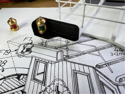

Upper Railing
The railing around the roof of the wheelhouse is a simple bent brass wire with machined brass pins for posts. I’ll offer a few tips that might make life easier for someone building this model, with reference to the photo below.
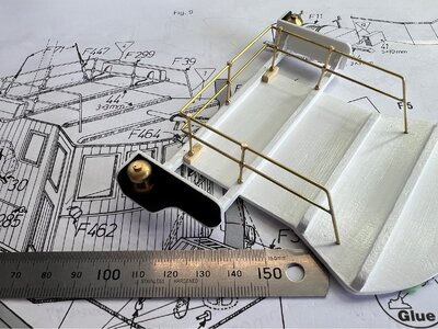
I like the idea of continuous rails where practical as they will be stronger and generally look better. Add to that, the fact that the posts are all straight pass-through, so they can’t be used as true corner posts with rails entering at 90 deg to one another. So, I added the posts to the rails as I bent them up, and then mounted the almost complete railing toward the end of the process.
For any future builders, here’s how I went about it (sorry about the detail, most readers can skip the next few paragraphs)…with reference to the photo above, I started with the upper rail. I bent the 60 deg angle at the bottom right of the photo (leaving the leg a bit long for latter trimming), then threaded two brass posts onto the wire (they need to go on before the next bend is made as they will not pass around the bent wire). Then bend the first right angle toward the upper right, then thread on another post (for the mid back), then bend another right angle and thread the final two posts, and then the last 60 deg angle down to the roof and snip off a bit long. Don’t glue any posts yet.
The lower rail was started with a right-angle bend (for the lower rear corner). If the posts are moved away from that corner on the top rail, then you can thread the lower rail through the rear mid post and the ones on the lower side before making the final right angle bend and moving the posts again to allow the rail to be threaded the final two posts…this is why the posts can’t be glue in the first step.
However, using the continuous rail with smooth rear corners requires a small change to the published plan for mounting. As none of the posts are true corner posts, and the rear mid post must sit on the back rail (else we clash with the rear mast), I needed to add new post mounting pads in front of the rear rail…see the unpainted blocks in the photo.
Afterward, I went back and had a close look at the Billing photos and they didn’t do it this way, it looks like they have one corner post mounted at 45 deg with the rail bent through accordingly, and the rails of the other corner don’t match perfectly, so I’m guessing that they glued the second corner’s rails to the post. My version is not true to the plan, but I prefer the way it looks.
The final step for me was to drill the mounting holes and get everything set up square on the roof before soft soldering the lower rail to the down sloping angle of the upper rail. Once filed clean, the other posts had a touch of thin CA applied where the wires pass through, then it was lifted off for spray painting before being final glued in place.
That’s probably more detail than you needed, but for someone starting out it might be useful.
So, what happened with the curved roof issue from the previous post?
I didn’t want to undo/redo all the work with the nav lights and railings, so my solution is... I sanded the rear wall of the wheelhouse to make it flat, and I reduced the side-to-side camber of the front wall a little by sanding. This means that the roof now only has to curve a small amount at the front and should work well. That sounds simple, but it meant removing some of the wiring for the cabin lights to allow the sanding and then fixing things afterward.
The railing around the roof of the wheelhouse is a simple bent brass wire with machined brass pins for posts. I’ll offer a few tips that might make life easier for someone building this model, with reference to the photo below.

I like the idea of continuous rails where practical as they will be stronger and generally look better. Add to that, the fact that the posts are all straight pass-through, so they can’t be used as true corner posts with rails entering at 90 deg to one another. So, I added the posts to the rails as I bent them up, and then mounted the almost complete railing toward the end of the process.
For any future builders, here’s how I went about it (sorry about the detail, most readers can skip the next few paragraphs)…with reference to the photo above, I started with the upper rail. I bent the 60 deg angle at the bottom right of the photo (leaving the leg a bit long for latter trimming), then threaded two brass posts onto the wire (they need to go on before the next bend is made as they will not pass around the bent wire). Then bend the first right angle toward the upper right, then thread on another post (for the mid back), then bend another right angle and thread the final two posts, and then the last 60 deg angle down to the roof and snip off a bit long. Don’t glue any posts yet.
The lower rail was started with a right-angle bend (for the lower rear corner). If the posts are moved away from that corner on the top rail, then you can thread the lower rail through the rear mid post and the ones on the lower side before making the final right angle bend and moving the posts again to allow the rail to be threaded the final two posts…this is why the posts can’t be glue in the first step.
However, using the continuous rail with smooth rear corners requires a small change to the published plan for mounting. As none of the posts are true corner posts, and the rear mid post must sit on the back rail (else we clash with the rear mast), I needed to add new post mounting pads in front of the rear rail…see the unpainted blocks in the photo.
Afterward, I went back and had a close look at the Billing photos and they didn’t do it this way, it looks like they have one corner post mounted at 45 deg with the rail bent through accordingly, and the rails of the other corner don’t match perfectly, so I’m guessing that they glued the second corner’s rails to the post. My version is not true to the plan, but I prefer the way it looks.
The final step for me was to drill the mounting holes and get everything set up square on the roof before soft soldering the lower rail to the down sloping angle of the upper rail. Once filed clean, the other posts had a touch of thin CA applied where the wires pass through, then it was lifted off for spray painting before being final glued in place.
That’s probably more detail than you needed, but for someone starting out it might be useful.
So, what happened with the curved roof issue from the previous post?
I didn’t want to undo/redo all the work with the nav lights and railings, so my solution is... I sanded the rear wall of the wheelhouse to make it flat, and I reduced the side-to-side camber of the front wall a little by sanding. This means that the roof now only has to curve a small amount at the front and should work well. That sounds simple, but it meant removing some of the wiring for the cabin lights to allow the sanding and then fixing things afterward.
Hi, I'm back from holidays and continuing on with the build...
Rear Door
There is a small door on the outside of the back wall of the wheelhouse that gave access to the under deck engine area in the real vessel. Plans for this detail are non-existent, so I estimated the size and style from the Billing photos. It’s a simple construction that I added veneer planks and door hardware to add a bit of interest. It is glued to the rear of the deckhouse, but at deck level rather than the house floor level. There probably should be some sort of panelling inside the wheelhouse to correspond to this access way, but it’s wasn't mentioned in the plans during that part of the build and I’ve already added a table to that area.
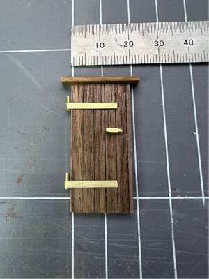
The brass fillings will be allowed to age to a less bright finish.
Rear Door
There is a small door on the outside of the back wall of the wheelhouse that gave access to the under deck engine area in the real vessel. Plans for this detail are non-existent, so I estimated the size and style from the Billing photos. It’s a simple construction that I added veneer planks and door hardware to add a bit of interest. It is glued to the rear of the deckhouse, but at deck level rather than the house floor level. There probably should be some sort of panelling inside the wheelhouse to correspond to this access way, but it’s wasn't mentioned in the plans during that part of the build and I’ve already added a table to that area.

The brass fillings will be allowed to age to a less bright finish.
Rear Mast
I’ve not had to make a tapered mast before, and I don’t have any type of lathe, so I’ll outline a little of what I did as it worked out pretty well.
The booklet does have a 1:1 drawing of the rear mast…but be careful, it’s not like it’s a reliable engineering drawing. I found that things like the mast antenna dimensions are different between the complete drawing of the mast and the drawing that is specifically describing the antenna. I also found that some of the fittings don’t fit correctly at the positions indicated in the drawings due to incorrect diameters. Not a major issue, just one to be aware of.
I started by tapering the supplied dowel, with the aim of getting something close to the dimensions of the drawing. To produce that taper, I used a small modeller’s hand plane (a David Mini), on the top half, to get it to very rough dimensions, with plenty to spare. Then I mounted the large end of the dowel in the chuck of a cordless drill (OH&S people look away now) and carefully held a piece of sandpaper against the dowel until it is turned into a nicely tapered mast. It works quite well, but watch out for the obvious risks…don’t get anything caught on the spinning mast (rag, sleeve etc), and be careful about how hot the sandpaper can get between your fingers. I used a cordless drill, as releasing the trigger brings it to a snappy halt...compared to my drill press.
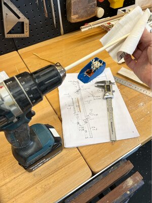
The mast will be finished using Sikkens Light Oak Exterior Decking finish...it has a nice stain finish, a good colour and is water based.
I’ve not had to make a tapered mast before, and I don’t have any type of lathe, so I’ll outline a little of what I did as it worked out pretty well.
The booklet does have a 1:1 drawing of the rear mast…but be careful, it’s not like it’s a reliable engineering drawing. I found that things like the mast antenna dimensions are different between the complete drawing of the mast and the drawing that is specifically describing the antenna. I also found that some of the fittings don’t fit correctly at the positions indicated in the drawings due to incorrect diameters. Not a major issue, just one to be aware of.
I started by tapering the supplied dowel, with the aim of getting something close to the dimensions of the drawing. To produce that taper, I used a small modeller’s hand plane (a David Mini), on the top half, to get it to very rough dimensions, with plenty to spare. Then I mounted the large end of the dowel in the chuck of a cordless drill (OH&S people look away now) and carefully held a piece of sandpaper against the dowel until it is turned into a nicely tapered mast. It works quite well, but watch out for the obvious risks…don’t get anything caught on the spinning mast (rag, sleeve etc), and be careful about how hot the sandpaper can get between your fingers. I used a cordless drill, as releasing the trigger brings it to a snappy halt...compared to my drill press.

The mast will be finished using Sikkens Light Oak Exterior Decking finish...it has a nice stain finish, a good colour and is water based.
Nope! not even as a special order.Hopefully and with all fingers crossed, Bunnings will introduce this into the NZ market.
To the mast fittings
The lower section of the mast has a white rear facing navigation light. This one is smaller than all the other lanterns in the kit (6mm vs 8mm), but it is still machined brass. The drawing shows it as having a hole in the rear of it that allows you to add a piece of brass wire to it for mounting to the mast. My fitting didn’t have the hole, so I drilled that…a hint for this, do it from the front (through the aperture of the lantern)…its much easier to drill an accurately placed hole in a concave section than to try drill the outer convex surface. The short piece of brass wire was fluxed using a flux pen and soft soldered in place.
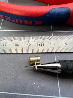
Now, it looks good, but it is begging me to add a lens and an LED so that we have a light showing at the rear (everything else faces forward). I also have power close by as the mast runs up the back of the deckhouse. I used a piece of frosted plastic, heated to fashion a curved lens, and since this lantern is small in diameter I can’t fit the lamp-holder as done in some of the others. For this one I inserted the LED in the correct position and then packed it from behind with thin strips of the same plastic as the lens.
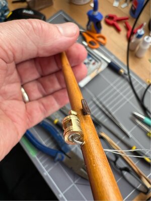
The wires will run up the mast between it and the back of the deckhouse, under the roof and down the internal conduit for power.
At the top of the rear mast there are fittings to take rope stays/shrouds and the antenna and its wires. Billing does supply some nice machined brass fittings for this, but I found that the sizing for some items is way off for the diameter of the mast, so I had to make a ring fitting (not sure what that’s called) from some brass strip…
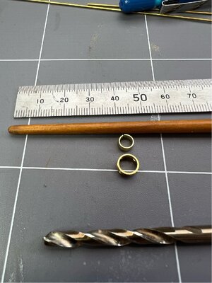
The lower ring is supplied, the upper is its replacement…they are sitting at the point that they should be on the mast. The original one is way too large to fit and allow the supplied pins to enter the mast as shown on the plan (shown in the next post).
The lower section of the mast has a white rear facing navigation light. This one is smaller than all the other lanterns in the kit (6mm vs 8mm), but it is still machined brass. The drawing shows it as having a hole in the rear of it that allows you to add a piece of brass wire to it for mounting to the mast. My fitting didn’t have the hole, so I drilled that…a hint for this, do it from the front (through the aperture of the lantern)…its much easier to drill an accurately placed hole in a concave section than to try drill the outer convex surface. The short piece of brass wire was fluxed using a flux pen and soft soldered in place.

Now, it looks good, but it is begging me to add a lens and an LED so that we have a light showing at the rear (everything else faces forward). I also have power close by as the mast runs up the back of the deckhouse. I used a piece of frosted plastic, heated to fashion a curved lens, and since this lantern is small in diameter I can’t fit the lamp-holder as done in some of the others. For this one I inserted the LED in the correct position and then packed it from behind with thin strips of the same plastic as the lens.

The wires will run up the mast between it and the back of the deckhouse, under the roof and down the internal conduit for power.
At the top of the rear mast there are fittings to take rope stays/shrouds and the antenna and its wires. Billing does supply some nice machined brass fittings for this, but I found that the sizing for some items is way off for the diameter of the mast, so I had to make a ring fitting (not sure what that’s called) from some brass strip…

The lower ring is supplied, the upper is its replacement…they are sitting at the point that they should be on the mast. The original one is way too large to fit and allow the supplied pins to enter the mast as shown on the plan (shown in the next post).


