Yep, I know what you mean, but don't worry, I've been making plenty and learning lots...you'll get to see some of them in the next few posts.IF YOU DO NOT MAKE MISTAKES, YOU WILL NEVER LEARN.EL CAPI
-

Win a Free Custom Engraved Brass Coin!!!
As a way to introduce our brass coins to the community, we will raffle off a free coin during the month of August. Follow link ABOVE for instructions for entering.
-

PRE-ORDER SHIPS IN SCALE TODAY!
The beloved Ships in Scale Magazine is back and charting a new course for 2026!
Discover new skills, new techniques, and new inspirations in every issue.
NOTE THAT OUR FIRST ISSUE WILL BE JAN/FEB 2026
You are using an out of date browser. It may not display this or other websites correctly.
You should upgrade or use an alternative browser.
You should upgrade or use an alternative browser.
Mary Ann by Billing Boats 472 - COMPLETED
- Thread starter pete_5
- Start date
- Watchers 20
-
- Tags
- billing boats mary ann
Sanding & Filling - making a start
This is another area that I’ve done a bit of reading to see what the best practice should be. Seems that, like many aspects of this sport, everyone has their own idea on that. You find something that works for your model or way of working and you stick to it.
This is going to be a painted hull, so I plan to get it pretty smooth through sanding of planks and the use of filler as makes sense. I don’t want to sand the planks too far, as it’s a single layer and I want to put it in the water, so it needs to remain reasonably strong. The inside has been clear epoxied as I have progressed. There are two small sections in the front two bulkheads, which are now fully enclosed, that missed out on a few planks being coated so I’ll be drilling a hole in the deck (before planking the deck) and injecting some thinned epoxy to get those sections coated.
----------------
STOP PRESS: As you will read in a later post, I eventually decided to fibreglass the exterior of the hull. If I was doing this again, I would probably do the epoxy/fibreglass step at this point - after sanding the planks but prior to adding any filler. This is likely to give a stronger bond to the timber, then the filling and final fairing of the hull would be done on top of the epoxied layer. However, I’ll leave the build log as per how the actual build progressed.
----------------
Filler choice
I wanted something that is easy to sand to shape, gives a good finish, takes paint well and isn’t troubled by increased humidity. I have used various types and brands on other non-model projects and one that I often go back to because of its results is Sika Filler 107. Although it’s water-based, it dries impervious, and is a wet-area rated filler that sands well. You won’t get mirror finish due to the grit size used in the filler, but I plan to use automotive spray putty over the filler and touch up with a fine filler if needed.
Here is the hull after a little further sanding, ready for a light all-over coat. There are still some raised edges on some planks (minor clinkering), some depressions where the plank thicknesses vary and all the plank butt joins. I’ve decided to finish the hull to the painting stage before adding the bulwarks, they are made of fine ply (about 1.5mm thick) and I think they would be at risk of damage from handling during the sanding & filling stage.

The filler is sand-able in an hour or so. I’m using sanding sticks with 180 grit, and also a cut-off heavy cardboard core (cylinder) from a clingwrap roll with some 240 for the tighter curves. Here it is after the first coat. The lower hull is reasonably straight, but as you move up the sides there are depressions between the bulkheads, and when you get it out in sunlight there are many spots that need a second coat (as expected).
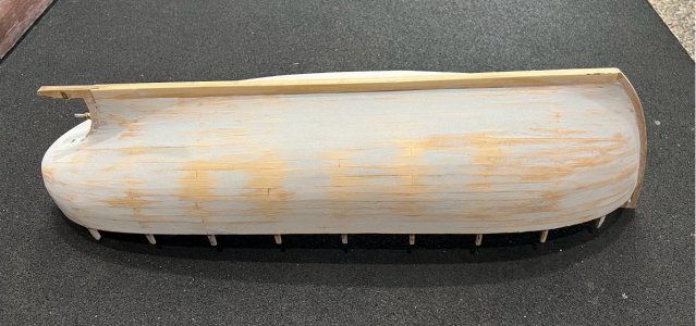
An interesting aside…I had the hull outside in the sun for a while (it’s winter here, so nothing too hot) to make sure the filler was dry before sanding. When I bought it back into the workshop I heard a ‘crack’…the air was maybe 10 deg C cooler in the workshop than the surface temp of the wood (it was barely warm to touch) and one of the planks appears to have separated from its neighbour - right in the centre of the photo above, two planks have separated by a fraction. I guess there was some internal stress in the plank that the temp difference overcame. I’m happy that it happened at this stage and not after getting it painted. I glued it up using some slow CA, squeezed into the gap and wiped clean. Good as new (hmmm…famous last words)
This is another area that I’ve done a bit of reading to see what the best practice should be. Seems that, like many aspects of this sport, everyone has their own idea on that. You find something that works for your model or way of working and you stick to it.
This is going to be a painted hull, so I plan to get it pretty smooth through sanding of planks and the use of filler as makes sense. I don’t want to sand the planks too far, as it’s a single layer and I want to put it in the water, so it needs to remain reasonably strong. The inside has been clear epoxied as I have progressed. There are two small sections in the front two bulkheads, which are now fully enclosed, that missed out on a few planks being coated so I’ll be drilling a hole in the deck (before planking the deck) and injecting some thinned epoxy to get those sections coated.
----------------
STOP PRESS: As you will read in a later post, I eventually decided to fibreglass the exterior of the hull. If I was doing this again, I would probably do the epoxy/fibreglass step at this point - after sanding the planks but prior to adding any filler. This is likely to give a stronger bond to the timber, then the filling and final fairing of the hull would be done on top of the epoxied layer. However, I’ll leave the build log as per how the actual build progressed.
----------------
Filler choice
I wanted something that is easy to sand to shape, gives a good finish, takes paint well and isn’t troubled by increased humidity. I have used various types and brands on other non-model projects and one that I often go back to because of its results is Sika Filler 107. Although it’s water-based, it dries impervious, and is a wet-area rated filler that sands well. You won’t get mirror finish due to the grit size used in the filler, but I plan to use automotive spray putty over the filler and touch up with a fine filler if needed.
Here is the hull after a little further sanding, ready for a light all-over coat. There are still some raised edges on some planks (minor clinkering), some depressions where the plank thicknesses vary and all the plank butt joins. I’ve decided to finish the hull to the painting stage before adding the bulwarks, they are made of fine ply (about 1.5mm thick) and I think they would be at risk of damage from handling during the sanding & filling stage.

The filler is sand-able in an hour or so. I’m using sanding sticks with 180 grit, and also a cut-off heavy cardboard core (cylinder) from a clingwrap roll with some 240 for the tighter curves. Here it is after the first coat. The lower hull is reasonably straight, but as you move up the sides there are depressions between the bulkheads, and when you get it out in sunlight there are many spots that need a second coat (as expected).

An interesting aside…I had the hull outside in the sun for a while (it’s winter here, so nothing too hot) to make sure the filler was dry before sanding. When I bought it back into the workshop I heard a ‘crack’…the air was maybe 10 deg C cooler in the workshop than the surface temp of the wood (it was barely warm to touch) and one of the planks appears to have separated from its neighbour - right in the centre of the photo above, two planks have separated by a fraction. I guess there was some internal stress in the plank that the temp difference overcame. I’m happy that it happened at this stage and not after getting it painted. I glued it up using some slow CA, squeezed into the gap and wiped clean. Good as new (hmmm…famous last words)
Sanding & Filling - Second coat and some protection
I feel that I’m heading in the right direction, but I’ll need another light coat of filler to bring some of those low areas up to a common level.
Here’s a shot after adding more filler, but before the final sanding…

While doing the final sanding I had to deal with the fact the bow stem is 6mm thick and the keel is close to 8mm, so I need to manage the transition between the two. For some time, I have also been thinking about protection for the keel…like it or not there will be times when the boat will be sitting directly on the ground (or run into something under the water). The solution to both issues will be some 0.5mm brass strip.
I don’t have any long lengths of brass strip, so I have cut appropriate width pieces, and I will add about 4 lengths along the keel and up the bow stem. The piece that wraps around the nose of the keel and up the stem will transition from the keel width to the stem width, and this will give me something to fill against to smooth that transition.
The brass was sanded on the back to give a surface key, and then epoxied directly to the timber surfaces. I’ve used rubber bands along the strip to hold it in place during drying and that has worked well.

Another area that needs some special attention…the rudder tube has ended up about 1mm below the level of the surface (I should have left it longer at installation and then filed it off at the end prior to the painting stage...another lesson learnt), so I used a countersinking drill bit to profile the area around the tube. This gives a smooth angle from surface level to the edge of the tube. I will have to be careful when painting to make sure that I get a good finish in that area.
Using the drill bit (by hand)…

The end result…
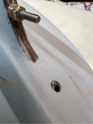
The photo above also shows a good example of the grit level of the filler being used at this stage. This is a tight close-up (the rudder tube is just over 3mm diameter). I think the grit will fill nicely with the spray putty.
----------------
STOP PRESS: The log tends to be a few weeks behind the current build, so in a later post you will read that I made a change to this area when fibreglassing the exterior of the hull (which meant the tube was even further below the surface)...so I decided to fill the area around the shaft with epoxy resin + filler powder, then sanded it flush with the surface. It looks better and I think it will be more serviceable in the longer term.
----------------
I feel that I’m heading in the right direction, but I’ll need another light coat of filler to bring some of those low areas up to a common level.
Here’s a shot after adding more filler, but before the final sanding…

While doing the final sanding I had to deal with the fact the bow stem is 6mm thick and the keel is close to 8mm, so I need to manage the transition between the two. For some time, I have also been thinking about protection for the keel…like it or not there will be times when the boat will be sitting directly on the ground (or run into something under the water). The solution to both issues will be some 0.5mm brass strip.
I don’t have any long lengths of brass strip, so I have cut appropriate width pieces, and I will add about 4 lengths along the keel and up the bow stem. The piece that wraps around the nose of the keel and up the stem will transition from the keel width to the stem width, and this will give me something to fill against to smooth that transition.
The brass was sanded on the back to give a surface key, and then epoxied directly to the timber surfaces. I’ve used rubber bands along the strip to hold it in place during drying and that has worked well.

Another area that needs some special attention…the rudder tube has ended up about 1mm below the level of the surface (I should have left it longer at installation and then filed it off at the end prior to the painting stage...another lesson learnt), so I used a countersinking drill bit to profile the area around the tube. This gives a smooth angle from surface level to the edge of the tube. I will have to be careful when painting to make sure that I get a good finish in that area.
Using the drill bit (by hand)…

The end result…

The photo above also shows a good example of the grit level of the filler being used at this stage. This is a tight close-up (the rudder tube is just over 3mm diameter). I think the grit will fill nicely with the spray putty.
----------------
STOP PRESS: The log tends to be a few weeks behind the current build, so in a later post you will read that I made a change to this area when fibreglassing the exterior of the hull (which meant the tube was even further below the surface)...so I decided to fill the area around the shaft with epoxy resin + filler powder, then sanded it flush with the surface. It looks better and I think it will be more serviceable in the longer term.
----------------
The Bulwarks
The kit supplies laser-cut 3-ply that is about 1.5mm thickness for the bulwarks. In my case I found that there was a reasonable amount of fettling required to get things to fit. There is some bending to do as the 5 pieces are flat and there are no straight sections on the hull.
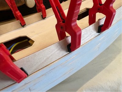
I chose to just wet the surface and use the planking iron to get the required shape for the side pieces. I found that I also had to sand the lower edge of each piece to fit it to both the sheer of the deck and also line up the separate pieces.
Don’t forget to cut the holes for the scuppers before gluing anything together. There was no instruction on where these holes are placed, so I measured this off the 1:1 plan. The hole sides where cut using a fine razor saw and its saw guide, and then a chisel & file to cut the tops. These will have internal covers added later after the deck has been planked.
The stern piece of the bulwark is quite tricky, it is a tight curve with some twist also needed to be set into the piece of ply…I found the hot air gun was good for getting a reasonable amount of heat into the piece, softening the ply, and then clamping it against the bulwark stanchions until it was cool and dry. This piece also needed some adjustment to the lower edge to get it to sit correctly against the upper and lower surfaces.
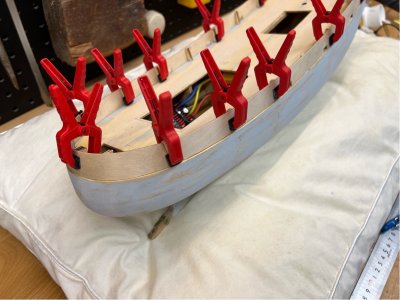
Overall, I found that the pieces are a little on the short side, so I ended up with a 2mm gap on one side and 3mm on the other. I decided to keep the gaps at the aft end and added some custom cut and shaped pieces between the curved stern piece and each of the side sections, over the stanchion in the area where they join. The ply pieces were glued with CA and the joins were then filled and faired.
I had to do a little adjustment to stanchion heights around the hull, some lowering at the stern and the addition of some material at the bow. The ones that were a little short are probably because I chose to keep the bulwarks a little higher at the bow (back to around bulwark frame 3), because I like the look of it.
The kit supplies laser-cut 3-ply that is about 1.5mm thickness for the bulwarks. In my case I found that there was a reasonable amount of fettling required to get things to fit. There is some bending to do as the 5 pieces are flat and there are no straight sections on the hull.

I chose to just wet the surface and use the planking iron to get the required shape for the side pieces. I found that I also had to sand the lower edge of each piece to fit it to both the sheer of the deck and also line up the separate pieces.
Don’t forget to cut the holes for the scuppers before gluing anything together. There was no instruction on where these holes are placed, so I measured this off the 1:1 plan. The hole sides where cut using a fine razor saw and its saw guide, and then a chisel & file to cut the tops. These will have internal covers added later after the deck has been planked.
The stern piece of the bulwark is quite tricky, it is a tight curve with some twist also needed to be set into the piece of ply…I found the hot air gun was good for getting a reasonable amount of heat into the piece, softening the ply, and then clamping it against the bulwark stanchions until it was cool and dry. This piece also needed some adjustment to the lower edge to get it to sit correctly against the upper and lower surfaces.

Overall, I found that the pieces are a little on the short side, so I ended up with a 2mm gap on one side and 3mm on the other. I decided to keep the gaps at the aft end and added some custom cut and shaped pieces between the curved stern piece and each of the side sections, over the stanchion in the area where they join. The ply pieces were glued with CA and the joins were then filled and faired.
I had to do a little adjustment to stanchion heights around the hull, some lowering at the stern and the addition of some material at the bow. The ones that were a little short are probably because I chose to keep the bulwarks a little higher at the bow (back to around bulwark frame 3), because I like the look of it.
Disaster strikes!
Well, it seemed like it at the time…a few posts back I mentioned that I had a single crack appear in the finished hull, which I glued up. Well, when I went out to the workshop to have a look at her the other day, I find 6 or 7 longitudinal splits in the planking - the planks had separated. The day before had been an unusually hot day here - I'm in Australia, it was still winter, but 29C and a very dry wind. The hull had been indoors in the workshop, and out of direct sunlight, but it seems that the combo of heat and low humidity has caused this problem.
I referred the problem to the forum to see what others could suggest to fix the problem…see the post here My Planking is Splitting
Here’s an example of one…there are 6 or 7 of them and they go through to the inside.
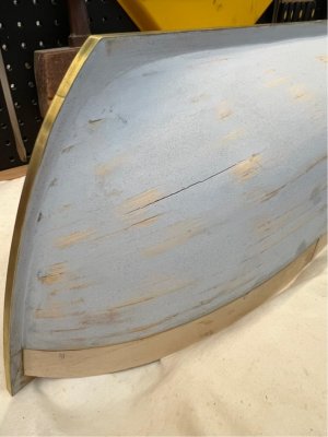
Given there is a separate thread on the suggested solutions, I’ll just summarise on the one that I used…I sanded the area around the splits, then used the back (flat edge) of a scalpel blade to clean and open the split without cutting anything out of it. Then I injected slow CA into the gap, wiped the surface and then used 180 grit sandpaper to sand across the gap while the glue was setting…adding dust and filler to the glue. This seems to have worked quite effectively (see the red arrow in the photo below…a similar crack, but on the other side of the hull)
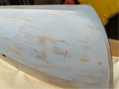
So, the immediate problem has been fixed, but I’m concerned about the longer term stability as humidity and temperature changes…and of course the fact that I’m planning on putting this boat in the water. Previously, I had convinced myself that I don’t need to fibreglass the hull (largely because of my inexperience), but I’ve had a re-think on that decision. In addition to ensuring it is watertight, the epoxy/glass layer will also make the hull stronger overall and help reduce the effects of wear and tear.
Now, I have no experience using fibreglass and epoxy, and I am a bit concerned about being able to form the glass layer around that curvaceous stern. So, I went back to the forum about this issue to see if anyone had experience using fibreglass on similar shapes…see the separate post here How to lay the fabric. The fabric is on order and I’ll be doing some preparation prior to the job.
I’m going to set up a test panel with both a section of bare sanded planks and also another with filled planks to see if the filler makes a significant difference to the epoxy adhesion. I’m also using epoxy products from Bote-Cote (Australia)…they make product for full size wooden boat builders. They have a product called TRPDA that is added to the mixed epoxy for the first coat, it modifies the epoxy to give it improved penetration ability and adds rot protection. I’m hoping it will help soak through the filler and into the timber substrate. We will see in a few days.
Well, it seemed like it at the time…a few posts back I mentioned that I had a single crack appear in the finished hull, which I glued up. Well, when I went out to the workshop to have a look at her the other day, I find 6 or 7 longitudinal splits in the planking - the planks had separated. The day before had been an unusually hot day here - I'm in Australia, it was still winter, but 29C and a very dry wind. The hull had been indoors in the workshop, and out of direct sunlight, but it seems that the combo of heat and low humidity has caused this problem.
I referred the problem to the forum to see what others could suggest to fix the problem…see the post here My Planking is Splitting
Here’s an example of one…there are 6 or 7 of them and they go through to the inside.

Given there is a separate thread on the suggested solutions, I’ll just summarise on the one that I used…I sanded the area around the splits, then used the back (flat edge) of a scalpel blade to clean and open the split without cutting anything out of it. Then I injected slow CA into the gap, wiped the surface and then used 180 grit sandpaper to sand across the gap while the glue was setting…adding dust and filler to the glue. This seems to have worked quite effectively (see the red arrow in the photo below…a similar crack, but on the other side of the hull)

So, the immediate problem has been fixed, but I’m concerned about the longer term stability as humidity and temperature changes…and of course the fact that I’m planning on putting this boat in the water. Previously, I had convinced myself that I don’t need to fibreglass the hull (largely because of my inexperience), but I’ve had a re-think on that decision. In addition to ensuring it is watertight, the epoxy/glass layer will also make the hull stronger overall and help reduce the effects of wear and tear.
Now, I have no experience using fibreglass and epoxy, and I am a bit concerned about being able to form the glass layer around that curvaceous stern. So, I went back to the forum about this issue to see if anyone had experience using fibreglass on similar shapes…see the separate post here How to lay the fabric. The fabric is on order and I’ll be doing some preparation prior to the job.
I’m going to set up a test panel with both a section of bare sanded planks and also another with filled planks to see if the filler makes a significant difference to the epoxy adhesion. I’m also using epoxy products from Bote-Cote (Australia)…they make product for full size wooden boat builders. They have a product called TRPDA that is added to the mixed epoxy for the first coat, it modifies the epoxy to give it improved penetration ability and adds rot protection. I’m hoping it will help soak through the filler and into the timber substrate. We will see in a few days.
Sealing the first two compartments
While I’m waiting on supplies, I have a few minor tasks that I can finish off. The first two bulkheads are solid ply with no means of access to the enclosed space, this means that at least 3 planks on each side in those areas did not get a coating of epoxy on the inside to help control moisture and watertightness…and given the recent problems, I want to fix that. The only way around this is to cut a few holes in each area of the deck above the compartments. Two holes allows you to shine a torch in one hole and still see and work through the other. I cut these with my Dremel by plunging the milling burr through the deck ply…this area will be patched and planked later and won’t be seen.
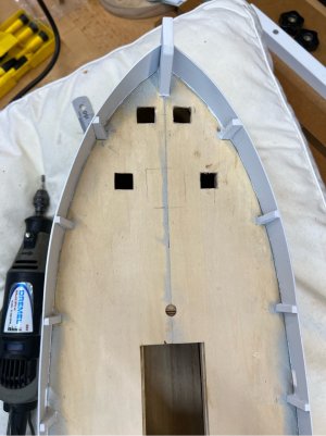
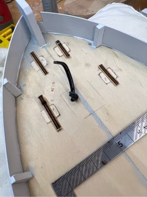
Epoxy resin was painted on the insides of the planks. I then shone a bright torch down the holes, and it paints a worrying picture (below) when viewed from the outside, but I’m hoping that most of that light is shining through a fairly thick layer of epoxy, you can see that the timber used for the hull in this kit is very light anyway (translucent at least under strong light). Anyway, the fibreglass layer to come will put my mind at ease.
The particularly bright gap halfway down was one of the planks that split earlier and was re-glued/filled with CA. And the black line in front of it, near the bow stem, is epoxy penetrating through from the inside in compartment 1 and soaking through the external filler (as hoped). These are in the three last planks to be installed and therefore missed their epoxy coating until now.

After getting that sorted, I made up some plugs from the ply left over in the kit. I temporarily glued a bar across the top of each plug before inserting them, so that they wouldn’t go through while the deck glue was drying, they were simply chiselled off later and then filled and sanded. Job done...and while I had access to compartment 2, I also added some wiring to bring power through from the main hold space so that I can add lighting to the forward nav lights.
While I’m waiting on supplies, I have a few minor tasks that I can finish off. The first two bulkheads are solid ply with no means of access to the enclosed space, this means that at least 3 planks on each side in those areas did not get a coating of epoxy on the inside to help control moisture and watertightness…and given the recent problems, I want to fix that. The only way around this is to cut a few holes in each area of the deck above the compartments. Two holes allows you to shine a torch in one hole and still see and work through the other. I cut these with my Dremel by plunging the milling burr through the deck ply…this area will be patched and planked later and won’t be seen.

Epoxy resin was painted on the insides of the planks. I then shone a bright torch down the holes, and it paints a worrying picture (below) when viewed from the outside, but I’m hoping that most of that light is shining through a fairly thick layer of epoxy, you can see that the timber used for the hull in this kit is very light anyway (translucent at least under strong light). Anyway, the fibreglass layer to come will put my mind at ease.
The particularly bright gap halfway down was one of the planks that split earlier and was re-glued/filled with CA. And the black line in front of it, near the bow stem, is epoxy penetrating through from the inside in compartment 1 and soaking through the external filler (as hoped). These are in the three last planks to be installed and therefore missed their epoxy coating until now.

After getting that sorted, I made up some plugs from the ply left over in the kit. I temporarily glued a bar across the top of each plug before inserting them, so that they wouldn’t go through while the deck glue was drying, they were simply chiselled off later and then filled and sanded. Job done...and while I had access to compartment 2, I also added some wiring to bring power through from the main hold space so that I can add lighting to the forward nav lights.

Deck coamings and the quarterdeck
Another small job. The kit is designed as a static display, so there is no need to worry about deck coamings at the openings (actually the ‘openings’ are not even there in that case), but that doesn’t apply in our RC example. I have three openings…one just behind the main mast for the battery access, the main opening under the wheelhouse for drivetrain and radio access, and under the rear quarterdeck for rudder linkage access.
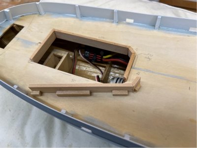
The main access hole needs a reasonably substantial coaming as it is also keeping the wheelhouse in place. I picked up a 10x3mm Oregon section at the local store, it’s nice and stiff and will be just the thing for this. The frame of the hull is not designed for this, so there is no existing frame to glue this to under the deck, so I added extra blocks behind each section of the coaming to give more purchase on the deck ply. The decking planks are only 0.5mm veneer mahogany so the height should be okay. Last piece to be added...
After adding the coaming, I thought that I’d better check that the battery will still fit (should have done that first, right?). I haven’t actually bought the battery yet, but I have a dummy wooden one that I made up ages ago, and guess what, it doesn’t fit! Width and depth are okay, but I can’t get enough angle for fitting the length, due to the projection of the coaming under the deck. I could modify the coaming, but I think it will be easier to buy a battery that is 5mm shorter!
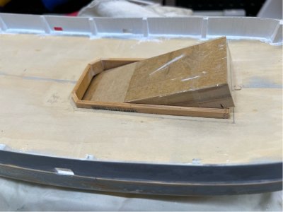
The rear coaming doesn’t take any weight, and gets covered by the quarterdeck, so I used some leftover hull planking timber to box it in.
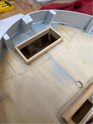
The opening up near the mast will be described when I’m adding the deck fittings in that area.
The Quarterdeck
This raised section of deck has almost no instruction in the booklet, so this is my interpretation. There is a lasercut 3-ply section to use as the basis of the deck. In my case the cutouts weren’t in quite the right places (my fault from very early in the build), so I enlarged the openings to suit the current positions of the bulwark stanchions and patched the ply deck to make it look neat before adding the planking (the planking is only 0.5mm veneer, so it has no strength on its own). The quarterdeck needs to sit a little higher than the main deck, and in my case I need to clear the height of the coaming around the rudder access. I added a range of short support beams under the ply for this. Here is the underside (that’s just the first coat of paint)…
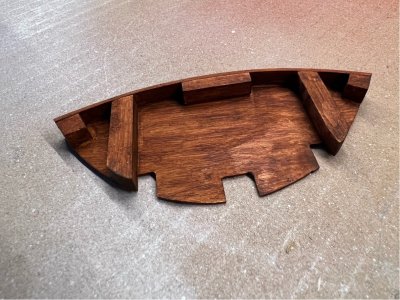
The front of the quarterdeck was closed in with a couple of lengths of walnut I had in stock, bent using a hot air gun then glued to the support members. I stained them a richer, more red colour to better match the planking timber. The top was planked with the supplied mahogany veneer, with the edges first marked with a black Sharpie, and then sprayed with matt poly after drying. The same veneer planks are used for the main deck, so I’m looking forward to getting to that.
Here it is in place...
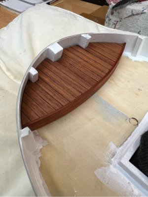
As an aside…I’ve been trying WeldBond white glue for these few jobs, it was getting a good rap from others in another thread. It works very well, it’s thicker than most white glues and allows a limited amount of adjustment before setting reasonably quickly. I plan to give it a go on all of the veneer decking to be done…easy cleanup with water before setting, and when cleaned it doesn’t seem to affect tints and clear coats like CA would.
That's all for today...back on to the fibreglassing task in the next post.
Another small job. The kit is designed as a static display, so there is no need to worry about deck coamings at the openings (actually the ‘openings’ are not even there in that case), but that doesn’t apply in our RC example. I have three openings…one just behind the main mast for the battery access, the main opening under the wheelhouse for drivetrain and radio access, and under the rear quarterdeck for rudder linkage access.
The main access hole needs a reasonably substantial coaming as it is also keeping the wheelhouse in place. I picked up a 10x3mm Oregon section at the local store, it’s nice and stiff and will be just the thing for this. The frame of the hull is not designed for this, so there is no existing frame to glue this to under the deck, so I added extra blocks behind each section of the coaming to give more purchase on the deck ply. The decking planks are only 0.5mm veneer mahogany so the height should be okay. Last piece to be added...

After adding the coaming, I thought that I’d better check that the battery will still fit (should have done that first, right?). I haven’t actually bought the battery yet, but I have a dummy wooden one that I made up ages ago, and guess what, it doesn’t fit! Width and depth are okay, but I can’t get enough angle for fitting the length, due to the projection of the coaming under the deck. I could modify the coaming, but I think it will be easier to buy a battery that is 5mm shorter!

The rear coaming doesn’t take any weight, and gets covered by the quarterdeck, so I used some leftover hull planking timber to box it in.

The opening up near the mast will be described when I’m adding the deck fittings in that area.
The Quarterdeck
This raised section of deck has almost no instruction in the booklet, so this is my interpretation. There is a lasercut 3-ply section to use as the basis of the deck. In my case the cutouts weren’t in quite the right places (my fault from very early in the build), so I enlarged the openings to suit the current positions of the bulwark stanchions and patched the ply deck to make it look neat before adding the planking (the planking is only 0.5mm veneer, so it has no strength on its own). The quarterdeck needs to sit a little higher than the main deck, and in my case I need to clear the height of the coaming around the rudder access. I added a range of short support beams under the ply for this. Here is the underside (that’s just the first coat of paint)…

The front of the quarterdeck was closed in with a couple of lengths of walnut I had in stock, bent using a hot air gun then glued to the support members. I stained them a richer, more red colour to better match the planking timber. The top was planked with the supplied mahogany veneer, with the edges first marked with a black Sharpie, and then sprayed with matt poly after drying. The same veneer planks are used for the main deck, so I’m looking forward to getting to that.
Here it is in place...

As an aside…I’ve been trying WeldBond white glue for these few jobs, it was getting a good rap from others in another thread. It works very well, it’s thicker than most white glues and allows a limited amount of adjustment before setting reasonably quickly. I plan to give it a go on all of the veneer decking to be done…easy cleanup with water before setting, and when cleaned it doesn’t seem to affect tints and clear coats like CA would.
That's all for today...back on to the fibreglassing task in the next post.
Back to the fibreglassing…and does the existing filler make a difference?
I now have all my supplies. I bought a few different weights of glass cloth and also random chopped strand mat. The chopped mat is very light weight, but it’s reasonably stiff and therefore impractical for this application but would be good on completely flat surfaces. Of the two cloths, I’ll be using the lightest weight (30 gsm or 0.88 oz/yd). You have to be careful handling and cutting it as it’s easy to put a pull in the weave. The upside is it will mould around quite tight curves with ease.
To the test…I was concerned that the filler that is already on the hull might be a problem and that I’ll need to sand it off before starting. I thought that the epoxy would stick to the filler surface, but I’d then get delamination between the filler and timber when a load was applied.
Here is the panel, with the epoxied glass already added to each test area. Bare timber on the left, and filled timber on the right.

I let it harden for a few days before seeing which side of the panel had the better adhesion, and particularly whether the right side would fail between the filler and timber layer. As it turns out they both perform similarly when trying to strip the glass layer or when trying to separate the planks. The epoxy (with the diluent additive) appears to have soaked through the filler and into the timber. So, I’ll proceed with the hull without sanding the filler from the surface.
Fibreglassing the hull
This will be done in two runs…each side of the hull.
A length of cloth was cut with plenty of overhang on all sides. There was a little preparation to do…the rudder bottom mount hardware was removed (I didn’t want to invertedly glue it in) and the rudder post was greased to stop epoxy sticking to it, or going down the rudder tube, the prop shaft was covered with tape, and the entire hull was given a very light sand and multiple passes with a clean rag to remove any oils from my hands and then the dust from the hull.
I already have the bulwarks mounted to the hull, so I plan to run the cloth right to the top of those. I see a small issue with that, as they sit slightly inboard of the hull sides for about 60% of the hull length…that little step will be difficult to get the cloth to mould around.
Here we are before getting started. The hull is sitting on wood blocks to raise the side above the bench, and is canted over to give me better access.
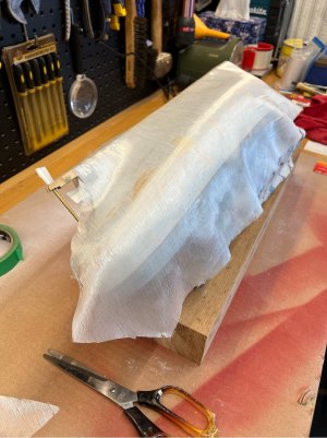
I mixed up 25ml of epoxy and diluent…a little more than was needed, but better that than too short. The epoxy was carefully poured on the fabric from the centre of the hull forwards and then to the rear, working down the side as I went. I used an old credit card to spread the epoxy, it works well as it doesn’t tug at the fabric when used at a low angle. In tight spots I tipped a small amount of epoxy on the end of the card for application because it can be tricky to pour small amounts in some places on the job.
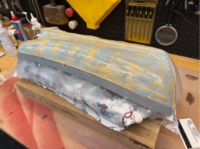
As expected, the step at the bulwark was a problem, in the end I used a sharp scalpel knife to cut the fabric along that line and allowed the cloth on the bulwark to sit on its surface, and the end of the fabric on the hull side to hang over the edge. This will be sanded to a square edge when everything is dry.
Given that this was my first go working with epoxy/glass fabric, I think it went smoothly. The fabric can handle quite tight complex curves due to the amount of ‘give’ afforded by the loose weave of the glass strands. It went around the stern without and wrinkles or bunching. The resulting finished layer is also very thin, so the overlap at the rear, when the other side is done, will be easy to feather to a smooth surface. It was around 20C when I did this job, so the epoxy had a pot life in excess of an hour, and it was a few hours before it really started to go off on the hull. By next morning it felt ready to continue.
Here is my novice list of things to be aware of…
I now have all my supplies. I bought a few different weights of glass cloth and also random chopped strand mat. The chopped mat is very light weight, but it’s reasonably stiff and therefore impractical for this application but would be good on completely flat surfaces. Of the two cloths, I’ll be using the lightest weight (30 gsm or 0.88 oz/yd). You have to be careful handling and cutting it as it’s easy to put a pull in the weave. The upside is it will mould around quite tight curves with ease.
To the test…I was concerned that the filler that is already on the hull might be a problem and that I’ll need to sand it off before starting. I thought that the epoxy would stick to the filler surface, but I’d then get delamination between the filler and timber when a load was applied.
Here is the panel, with the epoxied glass already added to each test area. Bare timber on the left, and filled timber on the right.

I let it harden for a few days before seeing which side of the panel had the better adhesion, and particularly whether the right side would fail between the filler and timber layer. As it turns out they both perform similarly when trying to strip the glass layer or when trying to separate the planks. The epoxy (with the diluent additive) appears to have soaked through the filler and into the timber. So, I’ll proceed with the hull without sanding the filler from the surface.
Fibreglassing the hull
This will be done in two runs…each side of the hull.
A length of cloth was cut with plenty of overhang on all sides. There was a little preparation to do…the rudder bottom mount hardware was removed (I didn’t want to invertedly glue it in) and the rudder post was greased to stop epoxy sticking to it, or going down the rudder tube, the prop shaft was covered with tape, and the entire hull was given a very light sand and multiple passes with a clean rag to remove any oils from my hands and then the dust from the hull.
I already have the bulwarks mounted to the hull, so I plan to run the cloth right to the top of those. I see a small issue with that, as they sit slightly inboard of the hull sides for about 60% of the hull length…that little step will be difficult to get the cloth to mould around.
Here we are before getting started. The hull is sitting on wood blocks to raise the side above the bench, and is canted over to give me better access.

I mixed up 25ml of epoxy and diluent…a little more than was needed, but better that than too short. The epoxy was carefully poured on the fabric from the centre of the hull forwards and then to the rear, working down the side as I went. I used an old credit card to spread the epoxy, it works well as it doesn’t tug at the fabric when used at a low angle. In tight spots I tipped a small amount of epoxy on the end of the card for application because it can be tricky to pour small amounts in some places on the job.

As expected, the step at the bulwark was a problem, in the end I used a sharp scalpel knife to cut the fabric along that line and allowed the cloth on the bulwark to sit on its surface, and the end of the fabric on the hull side to hang over the edge. This will be sanded to a square edge when everything is dry.
Given that this was my first go working with epoxy/glass fabric, I think it went smoothly. The fabric can handle quite tight complex curves due to the amount of ‘give’ afforded by the loose weave of the glass strands. It went around the stern without and wrinkles or bunching. The resulting finished layer is also very thin, so the overlap at the rear, when the other side is done, will be easy to feather to a smooth surface. It was around 20C when I did this job, so the epoxy had a pot life in excess of an hour, and it was a few hours before it really started to go off on the hull. By next morning it felt ready to continue.
Here is my novice list of things to be aware of…
- Don’t get too fussy during application, the more you play with it, the greater the chance of pulling the fabric strands
- Make sure that the fabric and surface underneath are fully wet (no air pockets), but don’t go overboard, you can get pockets of resin if too much is applied without adequate smoothing
- Don’t try to fully fill the fabric weave on the first application (you will get runs), the filling happens in the subsequent epoxy layers
- Don’t be concerned about all that overhang, it’s so easy to remove when hardened, with sharp fine sandpaper along an edge
- Openings, like the scuppers (see above), are easy to cut out and file after allowing hardening overnight. Don’t try to cut anything while the epoxy is setting.
- Don’t try to warm things after applying the resin…you will get bubbles form under the wet resin/glass layer (yes, I tried!)
- Use disposable cups, stirrers, brushes etc where possible…it’s generally not worth trying to clean epoxy from most things. Tools can be cleaned with denatured alcohol if needed.
- Use nitrile rubber gloves, sticky epoxy can be cleaned from your skin with standard workshop hand-scrub creams…no need to use nasty solvents
- Remember that almost any ‘mistake’ can be corrected after hardening with sandpaper and maybe more epoxy or cloth…just don’t get epoxy into any moving parts
Finishing the epoxied layer
I'll start with an outline of the overall process I used...it's based on the writings of others more experienced than me, but like most things there are many different paths to the same destination.
Here is the end of step 1 (both sides covered and hardened)...it’s now time to remove the overhangs and lightly sand (ie step 2 & 3). You'll see a few lighter blue areas amongst the filled sections, these are not air pockets under the fabric, they are where CA glue has already soaked into the filler (during the fixes shown earlier) and the epoxy has glued directly to it rather than soaked through like it does elsewhere.

Step 2: The fabric overhang is allowed to dry before trying to remove it. Removing it is as simple as grabbing a fresh piece of 240 grit paper and sanding lightly across the edge that it overhangs. It comes off cleanly with only a light rub. You should wear a dust mask during this task as fine glass fibres will be created, and they can float around.

Step 3: The entire hull has had a light sand to remove dust and strands, and give the surface a good key for the next coat. In future, I wouldn't sand as far as I have here, it's not needed at this point.
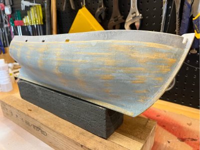
Step 4 & 5: The hull has been cleaned and recoated using a cut foam brush. It’s surprising how quickly the coating starts to fill the fabric and form a smooth glossy layer. This photo was taken after the coat had dried overnight.
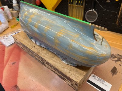
Step 6: The entire hull was wet sanded with 300 grit paper. This showed that I need to be careful applying the 2nd & 3rd coats as it is easy to get minor runs and thick edges at the bottom of vertical surfaces, like the top edge of the bulwarks (they are upside down during coating). I think I was probably too concerned about ‘filling’ the fabric weave…when it’s actually going to look after itself if you use the three coat process.
Here is the sanded hull ready for the last coat. It’s not perfectly smooth as the last of the bumps and dips will be filled after the next coat. Although it looks like the surface has been sanded back to the timber in some areas, that is just where there was no filler on the timber before starting the fibreglassing and the cloth and resin is now transparent.

Step 7 & 8: The final coat. Make sure everything is nice and clean, and that you have a good day weather-wise…I ended up waiting a week for a cold & wet spell to pass before doing this coat. I did this one with a fairly coarse camel hair brush (the epoxy people recommend them for the job), it worked much better than the foam wedge type brush used on coat 2...better control of coating thickness.
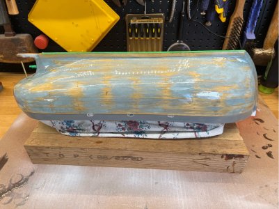
Step 9: Once that was dry, the entire hull was wet sanded again, being careful to only remove the high spots, as preparation for the final filling stage. This is the end of the epoxy/glass process. Overall, this was not anywhere near as stressful as I thought that it might be. The hull is certainly better off for having done it, and I wouldn’t hesitate to use it again on a model going in the water.
Next time I'll be back to the final filling stage prior to starting the painting.
I'll start with an outline of the overall process I used...it's based on the writings of others more experienced than me, but like most things there are many different paths to the same destination.
- Add resin/glass layer to the hull and allow to dry
- Remove overhangs with sandpaper
- Lightly dry sand the entire hull with 240 grit, being careful not to take too much off, just lumps, dust, any wayward glass strands. At this stage it is very easy to remove that protective layer that you’ve just added
- Remove dust and any oils from touching the surface etc
- Add second layer of resin only, being careful not to allow runs/drips to form, and allow to dry…this is when the fabric weave starts to fill
- Wet sand with 300 grit, aiming for a reasonably smooth surface without going so far that you start removing fabric. Remember that final smoothing is done with filler after this whole process.
- Remove dust and any oils from touching the sanded surface etc
- Add third layer of resin only, being careful not to allow runs/drips to form, and allow to dry. It should be shiny and smooth.
- Wet sand with 450 grit, aiming for a reasonably smooth surface, remembering that final smoothing is done with filler in the next phase.
Here is the end of step 1 (both sides covered and hardened)...it’s now time to remove the overhangs and lightly sand (ie step 2 & 3). You'll see a few lighter blue areas amongst the filled sections, these are not air pockets under the fabric, they are where CA glue has already soaked into the filler (during the fixes shown earlier) and the epoxy has glued directly to it rather than soaked through like it does elsewhere.

Step 2: The fabric overhang is allowed to dry before trying to remove it. Removing it is as simple as grabbing a fresh piece of 240 grit paper and sanding lightly across the edge that it overhangs. It comes off cleanly with only a light rub. You should wear a dust mask during this task as fine glass fibres will be created, and they can float around.

Step 3: The entire hull has had a light sand to remove dust and strands, and give the surface a good key for the next coat. In future, I wouldn't sand as far as I have here, it's not needed at this point.

Step 4 & 5: The hull has been cleaned and recoated using a cut foam brush. It’s surprising how quickly the coating starts to fill the fabric and form a smooth glossy layer. This photo was taken after the coat had dried overnight.

Step 6: The entire hull was wet sanded with 300 grit paper. This showed that I need to be careful applying the 2nd & 3rd coats as it is easy to get minor runs and thick edges at the bottom of vertical surfaces, like the top edge of the bulwarks (they are upside down during coating). I think I was probably too concerned about ‘filling’ the fabric weave…when it’s actually going to look after itself if you use the three coat process.
Here is the sanded hull ready for the last coat. It’s not perfectly smooth as the last of the bumps and dips will be filled after the next coat. Although it looks like the surface has been sanded back to the timber in some areas, that is just where there was no filler on the timber before starting the fibreglassing and the cloth and resin is now transparent.

Step 7 & 8: The final coat. Make sure everything is nice and clean, and that you have a good day weather-wise…I ended up waiting a week for a cold & wet spell to pass before doing this coat. I did this one with a fairly coarse camel hair brush (the epoxy people recommend them for the job), it worked much better than the foam wedge type brush used on coat 2...better control of coating thickness.

Step 9: Once that was dry, the entire hull was wet sanded again, being careful to only remove the high spots, as preparation for the final filling stage. This is the end of the epoxy/glass process. Overall, this was not anywhere near as stressful as I thought that it might be. The hull is certainly better off for having done it, and I wouldn’t hesitate to use it again on a model going in the water.
Next time I'll be back to the final filling stage prior to starting the painting.
- Joined
- Dec 3, 2022
- Messages
- 1,547
- Points
- 488

That was a very clear and enjoyable log. A good read on a dull afternoon. Thank you.
That lateral splitting along some of your hull planks - I suspect that the long soaking of the wood later led to a powerful shrinkage side to side. I've had similar problems after gluing down damp planks. (Sorry if that was all discusses in the auxiliary thread on fillers.)
That lateral splitting along some of your hull planks - I suspect that the long soaking of the wood later led to a powerful shrinkage side to side. I've had similar problems after gluing down damp planks. (Sorry if that was all discusses in the auxiliary thread on fillers.)
Hi Smithy, thanks. I've recently been checking in on your build of Alert, also very well written with good photos...that solution to clinkering the planks was something I'd not seen before. And, I think you're right about my plank soaking, seemed like a good idea at the time, but I've learned a lesson there and will do it differently next time. The silver-lining is that I've now got a model that will be stronger in the long run and I've learnt how to 'glass a hull...so no loss.That was a very clear and enjoyable log. A good read on a dull afternoon. Thank you.
That lateral splitting along some of your hull planks - I suspect that the long soaking of the wood later led to a powerful shrinkage side to side. I've had similar problems after gluing down damp planks. (Sorry if that was all discusses in the auxiliary thread on fillers.)
- Joined
- Dec 3, 2022
- Messages
- 1,547
- Points
- 488

Final Filling
I feel like I’ve been here a few times already, but let’s hope this will be the real thing. After giving the hull a wet sand in the step above, being careful to always use a sanding block, and one that was long enough to ensure that I wasn’t sanding local dips and hollows, I gave everything a wash and started to fill with a finer modelling filler (Deluxe Materials Model Lite). This filler is very light to put on but dries reasonably hard and has a quite fine finish that sands well with fine grit paper. It can be difficult to get it to stick to the surface when wet, but grips very well after it has set.
I ended up giving it an all over buttering to start with because of the difficulty getting it on the surface, it was applied with a flat putty blade.…
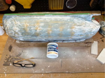
I wasn’t sure about wet sanding this filler, it is water soluble before setting, but appears to dry impervious to light application of water. To be on the safe side I used 400 grit paper but left it dry. Most of the filler is removed again during sanding, as I’m just trying to fill the dips and hollows. There were a couple of places where I did try to do some minor re-profiling of the shape, in particular on either side of the stern post where the surface rapidly changes from vertical to horizontal and I felt it needed a little more meat on one side to give a smooth transition.
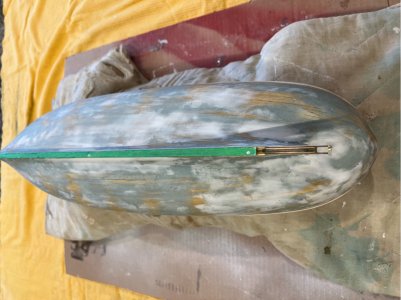
But where do you stop? I could keep touching up and sanding back forever…in the end I needed to find a happy point where I thought it was pretty close and I knew that I still have the spray putty to come where minor imperfections could be fixed. I was also keen to get a single consistent colour on it so that I could gauge by eye how it looked (very hard to do when it is mottled).
For comparison, here it is before I moved onto the painting stage…
The Rubbing strake
Before moving on to paint, I want to add the rubbing strake. This needs to be securely glued to hull and I think that would be best done now before any paint is added. I’m not sure if this is the conventional order of things, but I’m not adding all of the other timber rubbing guards down the sides that protect the hull from the trawling boards/nets etc as they will make it difficult to get a nicely sanded surface on the spray putty and primer. I’ll add them just prior to the final colour coats.
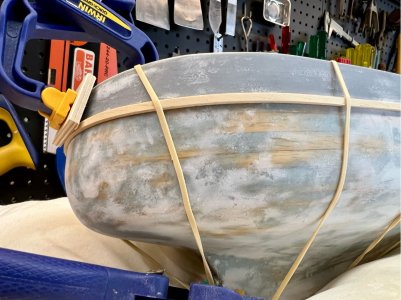
The rubbing strake is a simple 3x1.8mm section. The kit provides four lengths which is plenty for this job. I initially planned to bend one right around the stern (as per the first few planks) and then do a run up each side to the bow stem, however the grain of the supplied timber wasn’t happy with that idea (it snapped, even with water and heat), so I changed that to having a join in the centre of the stern and another join up fairly close to the bow. The timbers were wet in a bath (but not soaked for any significant time) and a hot planking iron used to form the curves. These were clamped, without glue, and held in place with rubber bands and a clamp to dry overnight.
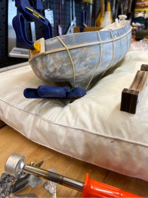
After drying, they were removed and the hull surface was given a light sand where they would sit, and then they were carefully glued along the entire length (I’m not making that mistake again!) with slow CA. This worked out well as it gave me time to re-position the strake to get it sitting properly along the sheer of the hull. I also wiped any excess away with a rag so that it wouldn’t have to be sanded again.
Here's a photo with to glued in place. There’s a join under that piece of ply and clamp, but it’s hardly visible. This small addition really starts to bring the hull alive, she’s starting to look like a real boat.
Next step...time to prime.
I feel like I’ve been here a few times already, but let’s hope this will be the real thing. After giving the hull a wet sand in the step above, being careful to always use a sanding block, and one that was long enough to ensure that I wasn’t sanding local dips and hollows, I gave everything a wash and started to fill with a finer modelling filler (Deluxe Materials Model Lite). This filler is very light to put on but dries reasonably hard and has a quite fine finish that sands well with fine grit paper. It can be difficult to get it to stick to the surface when wet, but grips very well after it has set.
I ended up giving it an all over buttering to start with because of the difficulty getting it on the surface, it was applied with a flat putty blade.…

I wasn’t sure about wet sanding this filler, it is water soluble before setting, but appears to dry impervious to light application of water. To be on the safe side I used 400 grit paper but left it dry. Most of the filler is removed again during sanding, as I’m just trying to fill the dips and hollows. There were a couple of places where I did try to do some minor re-profiling of the shape, in particular on either side of the stern post where the surface rapidly changes from vertical to horizontal and I felt it needed a little more meat on one side to give a smooth transition.
But where do you stop? I could keep touching up and sanding back forever…in the end I needed to find a happy point where I thought it was pretty close and I knew that I still have the spray putty to come where minor imperfections could be fixed. I was also keen to get a single consistent colour on it so that I could gauge by eye how it looked (very hard to do when it is mottled).
For comparison, here it is before I moved onto the painting stage…

The Rubbing strake
Before moving on to paint, I want to add the rubbing strake. This needs to be securely glued to hull and I think that would be best done now before any paint is added. I’m not sure if this is the conventional order of things, but I’m not adding all of the other timber rubbing guards down the sides that protect the hull from the trawling boards/nets etc as they will make it difficult to get a nicely sanded surface on the spray putty and primer. I’ll add them just prior to the final colour coats.
The rubbing strake is a simple 3x1.8mm section. The kit provides four lengths which is plenty for this job. I initially planned to bend one right around the stern (as per the first few planks) and then do a run up each side to the bow stem, however the grain of the supplied timber wasn’t happy with that idea (it snapped, even with water and heat), so I changed that to having a join in the centre of the stern and another join up fairly close to the bow. The timbers were wet in a bath (but not soaked for any significant time) and a hot planking iron used to form the curves. These were clamped, without glue, and held in place with rubber bands and a clamp to dry overnight.

After drying, they were removed and the hull surface was given a light sand where they would sit, and then they were carefully glued along the entire length (I’m not making that mistake again!) with slow CA. This worked out well as it gave me time to re-position the strake to get it sitting properly along the sheer of the hull. I also wiped any excess away with a rag so that it wouldn’t have to be sanded again.
Here's a photo with to glued in place. There’s a join under that piece of ply and clamp, but it’s hardly visible. This small addition really starts to bring the hull alive, she’s starting to look like a real boat.

Next step...time to prime.
Prime coat
This will be the real test…it’s quite hard to see the true shape of the hull when the surface is multicoloured with patches of filler, so adding a uniform colour to the surface will allow me to judge whether the shape is okay or needs further work.
I’m using an automotive rattle can spray-putty as the first coat(s). It should give sufficient build to allow a light sand to smooth things off before the prime and paint. The inside of the bulwark has already been painted white, so I masked off the scupper holes with tape and will be careful about shielding that internal surface from overspray. The initial coat was applied with the hull upside down.
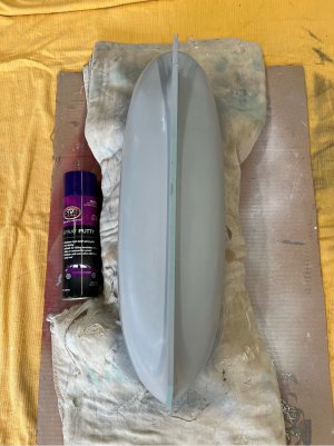
And then turned right-side up and the topside of the rubbing strake coated while the deck was masked with some paper. As you can see, I don’t have a spray booth, but I used drop sheets on the floor of my workshop and large pieces of cardboard standing around it to contain overspray. For small jobs like this is works okay provided I can leave the area while the fumes drift away.
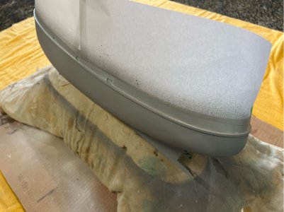
Well, as expected, having a consistent colour makes a huge difference to the look of the hull. I’m pretty happy with the shape and fairing. There are a few minor spots where the planks were probably thicker (or my fairing of the bulkheads wasn’t perfect) and I can see minor bumps/dips…but you do have to look for them...see the pencilled area in this shot.
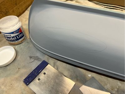
Now, I could leave these as is, but I do know that I’ll be kicking myself down the track if I don’t fix these little issues while I can. The Model Lite shown in the photo was used to build up that area and a few others, particularly around the stern. This was sanded back and a fresh coat of spray putty applied. Things were better, but still not as good as they could be.
The following day, a fresh set of eyes also noticed that the stern wasn’t symmetrical on the underside aft of the rudder post, one side being a little ‘fuller’ than the other. I’d already had a go at the stern with the Model Lite but wasn’t having a lot of luck getting a good shape and a nice feathering back to the existing surface, so I went back to the Sika 107 filler. I feel that it sticks better when wet and leaves a very easily sanded surface when dry.
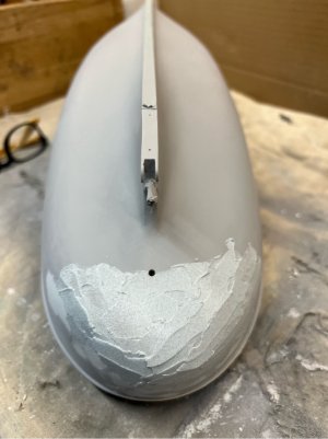
After sanding, I finally got to the shape that I wanted, but there were plenty of pin-holes left in the next coat of the putty (sprayed locally to the fix). One of the good things about the spray-putty is that you can add a few layers and quickly fill those pin-holes. The entire hull was given another coat and then wet-rubbed with 600 grit…not that I needed it that fine, but it slows the process a bit and I know that I’m inclined to over-do the sanding. So we're now ready for priming (honest...even I'm getting tired of applying and sanding filler).
The primer is also an automotive rattle can spray. It feels like a thinner version of the putty. The manufacturer suggests three thin coats, so that’s what it got, and then a gentle wet rub back with the 600 grit. Here's the result...
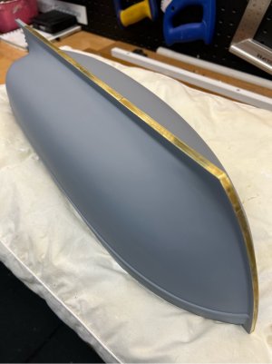
Yes, it has lost all vestiges of a timber hull…but it has been a great learning opportunity for me in what can be achieved with a bit of fibreglass/filler and some patience. I’m happy with it and I can still look at the planks on the inside of the hull!
Now that I have a smooth hull, the next job is to add the extra rubbing rails that run down the sides of the hull to protect it from the trawling / otter boards and other wear, before applying the final colour.
This will be the real test…it’s quite hard to see the true shape of the hull when the surface is multicoloured with patches of filler, so adding a uniform colour to the surface will allow me to judge whether the shape is okay or needs further work.
I’m using an automotive rattle can spray-putty as the first coat(s). It should give sufficient build to allow a light sand to smooth things off before the prime and paint. The inside of the bulwark has already been painted white, so I masked off the scupper holes with tape and will be careful about shielding that internal surface from overspray. The initial coat was applied with the hull upside down.

And then turned right-side up and the topside of the rubbing strake coated while the deck was masked with some paper. As you can see, I don’t have a spray booth, but I used drop sheets on the floor of my workshop and large pieces of cardboard standing around it to contain overspray. For small jobs like this is works okay provided I can leave the area while the fumes drift away.

Well, as expected, having a consistent colour makes a huge difference to the look of the hull. I’m pretty happy with the shape and fairing. There are a few minor spots where the planks were probably thicker (or my fairing of the bulkheads wasn’t perfect) and I can see minor bumps/dips…but you do have to look for them...see the pencilled area in this shot.

Now, I could leave these as is, but I do know that I’ll be kicking myself down the track if I don’t fix these little issues while I can. The Model Lite shown in the photo was used to build up that area and a few others, particularly around the stern. This was sanded back and a fresh coat of spray putty applied. Things were better, but still not as good as they could be.
The following day, a fresh set of eyes also noticed that the stern wasn’t symmetrical on the underside aft of the rudder post, one side being a little ‘fuller’ than the other. I’d already had a go at the stern with the Model Lite but wasn’t having a lot of luck getting a good shape and a nice feathering back to the existing surface, so I went back to the Sika 107 filler. I feel that it sticks better when wet and leaves a very easily sanded surface when dry.

After sanding, I finally got to the shape that I wanted, but there were plenty of pin-holes left in the next coat of the putty (sprayed locally to the fix). One of the good things about the spray-putty is that you can add a few layers and quickly fill those pin-holes. The entire hull was given another coat and then wet-rubbed with 600 grit…not that I needed it that fine, but it slows the process a bit and I know that I’m inclined to over-do the sanding. So we're now ready for priming (honest...even I'm getting tired of applying and sanding filler).
The primer is also an automotive rattle can spray. It feels like a thinner version of the putty. The manufacturer suggests three thin coats, so that’s what it got, and then a gentle wet rub back with the 600 grit. Here's the result...

Yes, it has lost all vestiges of a timber hull…but it has been a great learning opportunity for me in what can be achieved with a bit of fibreglass/filler and some patience. I’m happy with it and I can still look at the planks on the inside of the hull!
Now that I have a smooth hull, the next job is to add the extra rubbing rails that run down the sides of the hull to protect it from the trawling / otter boards and other wear, before applying the final colour.
That was a very enjoyable read. It is looking very nice!
I read something about a beginner earlier in the thread, but you are surely no beginner. Lots of cool techniques applied here.
I read something about a beginner earlier in the thread, but you are surely no beginner. Lots of cool techniques applied here.
- Joined
- Dec 3, 2022
- Messages
- 1,547
- Points
- 488

Prime coat
...
View attachment 480148
… a bit of fibreglass/filler and some patience. I’m happy with it…
Congratulations on that smooth and lovely hull. You certainly worked hard for it.
More Rubbing rails
The starboard side of the upper hull has two areas where there are rubbing rails that run almost vertically to protect the side of the hull from damage from trawling activities. There are no detailed instructions for these, but they are shown on the side view of the full-size plan. I used this to measure the positioning and size of the rails. The plans indicate that the rails below the rubbing strake should be made from 1x1mm stock, but I only found 1x0.7mm, that’s close and makes the job easier as it will bend to fit the hull shape.
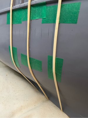
I started out by marking up the hull in pencil to make sure that it was all going to look okay, and to act as a guide for glueing. The horizontal line is the waterline.
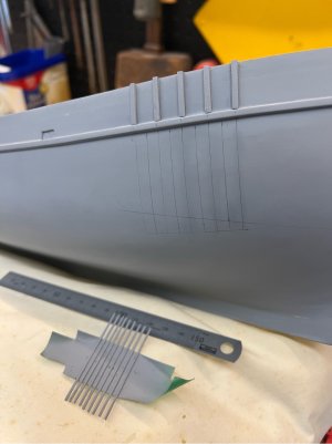
The larger rails (2x2mm) above the rubbing strake are at 12mm centres and are perpendicular to that strake. The finer rails below the strake are at 6mm centres and a uniform 50mm length on the set near the bow. Given that the hull has been painted to the primer stage, I pre-painted the new rails on three sides with the same primer…they are stuck on masking tape that is sticky side up. Before glueing them to the hull, I used an eraser to remove the pencil lines, except for a tick mark at each end outside the glueing area, so the graphite doesn’t affect the glue.
Each rail was glued, any squeeze-out removed, and then masking tape and rubber bands used to hold them until the glue (WeldBond) had set.
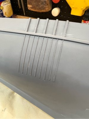
They’ve stuck nicely. I’ve done a bit of minor clean up and they are now ready for the final hull painting.
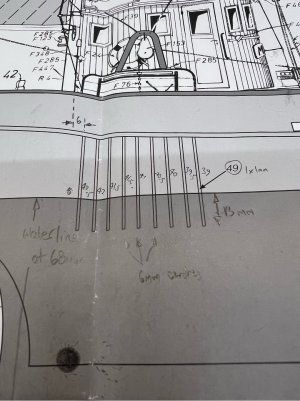
There’s another set toward the stern, near the rear of the wheelhouse. These ones are below the rubbing strake only. According to the 1:1 plan, their lengths are all slightly different and dependent on the waterline – they all extend a uniform 13mm below the waterline. These ones are also set at a different angle to the set up front, these ones are parallel to the back wall of the wheelhouse, rather than perpendicular to the rubbing strake – it’s a small difference but would be obvious later if you missed it.
Here’s the plan with my extra annotations to explain…
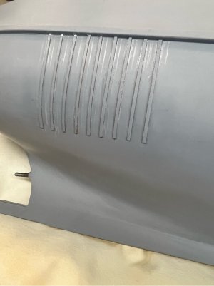
These were treated the same way as the other set…I did a few at a time, but every 2nd or 3rd one so that you can tape them without interfering with the others you are currently working on, then next round start filling in the others.
And, here is the finished job, prior to another localised coat of primer before the outer paint coats are applied.
Next time I'll be making some minor changes to the rudder and its mount before painting.
The starboard side of the upper hull has two areas where there are rubbing rails that run almost vertically to protect the side of the hull from damage from trawling activities. There are no detailed instructions for these, but they are shown on the side view of the full-size plan. I used this to measure the positioning and size of the rails. The plans indicate that the rails below the rubbing strake should be made from 1x1mm stock, but I only found 1x0.7mm, that’s close and makes the job easier as it will bend to fit the hull shape.
I started out by marking up the hull in pencil to make sure that it was all going to look okay, and to act as a guide for glueing. The horizontal line is the waterline.

The larger rails (2x2mm) above the rubbing strake are at 12mm centres and are perpendicular to that strake. The finer rails below the strake are at 6mm centres and a uniform 50mm length on the set near the bow. Given that the hull has been painted to the primer stage, I pre-painted the new rails on three sides with the same primer…they are stuck on masking tape that is sticky side up. Before glueing them to the hull, I used an eraser to remove the pencil lines, except for a tick mark at each end outside the glueing area, so the graphite doesn’t affect the glue.
Each rail was glued, any squeeze-out removed, and then masking tape and rubber bands used to hold them until the glue (WeldBond) had set.

They’ve stuck nicely. I’ve done a bit of minor clean up and they are now ready for the final hull painting.

There’s another set toward the stern, near the rear of the wheelhouse. These ones are below the rubbing strake only. According to the 1:1 plan, their lengths are all slightly different and dependent on the waterline – they all extend a uniform 13mm below the waterline. These ones are also set at a different angle to the set up front, these ones are parallel to the back wall of the wheelhouse, rather than perpendicular to the rubbing strake – it’s a small difference but would be obvious later if you missed it.
Here’s the plan with my extra annotations to explain…

These were treated the same way as the other set…I did a few at a time, but every 2nd or 3rd one so that you can tape them without interfering with the others you are currently working on, then next round start filling in the others.
And, here is the finished job, prior to another localised coat of primer before the outer paint coats are applied.

Next time I'll be making some minor changes to the rudder and its mount before painting.
Finalising the rudder and its mount
You may remember back toward the start of this project (post #6 to #8), that I decided to replace the simple sheet ply and dowel arrangement for the rudder due to this build being for RC. Instead, everything was made in brass but I only got to the stage of bending and shaping the rudder, but not finishing it and attaching it to the rudder post. First, I need to join and seal the rear edge of the bent sheet brass rudder blade, then fill the interior void of the rudder with epoxy resin, and glue it to the rudder post.
To join the rear edge, I decided to soft solder this join. The brass sheet is very thin (0.5mm) and I don’t fancy heating that to brazing temperatures with a flame. The inside is eventually going to be epoxy filled, so a soft soldered joint will be plenty strong enough. The area to be soldered was sanded to give a nice bare edge, then thoroughly degreased, and fluxed with an electronics flux solution. My usual soldering iron is too fine for this sort of work, so I thought that I’d try the trusty Makita hot air gun (~600C at max setting). The rudder was propped up in a few bulldog clips to hold the edges closed and heated. It didn’t take too long to get up to temp and the solder wicked into the joint as you would hope. A bit of cleaning with fine grit paper and steel wool and it looks good.
The straps around the rudder (2mm wide strips of brass) were cleaned up and these were attached using thin CA to wick into the joint…that worked really well (except for also joining a few fingers together! The fine nozzle extension had split, and I didn’t realise). I hadn’t used thin CA before…near instant bite and great wicking ability. I wouldn’t use it everywhere, but good for this job.
Alright, before gluing in the rudder post I’d better run some checks on the hull, as it hasn’t been inserted in the completed form. Does the rudder move freely?, and does everything fit in when installed from below as planned? Well…that’s a no and a no.
The rudder movement is being constrained by the hull. This was first tested months ago when the hull was just at keel stage, no frame or planking…now the top edge of the rudder blade was being stopped short by the ‘fuller’ hull surface. This was a simple fix, just re-profile the shape so that it will turn from side to side. It will now go almost 90 deg in either direction.
Next, the bottom mount that I had previously built works fine when you are just testing it with the free rudder post, with no rudder attached. However, when the rudder is fixed to the post, the shaft cannot slide up far enough into the hull to fit the bottom of the shaft into my fabricated lower bush. So, back to the drawing board…and a much simpler solution now presents itself.
To refresh your memory without having to dredge back through the log, here is the existing design…the bottom end of the rudder post sits in a short piece of brass tube that is epoxied inside a shaped bent brass strip.
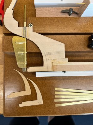
The problem is that the bottom of the keel now has the two cheeks shown (labelled 17 in the photo) glued in place and they prevent the lower bush being manoeuvred into place without deforming the strip and popping the epoxied bush off the strip. As it turns out, a better solution was already looking at me…I had since put a heavier brass strip over the bottom of the existing thin strip as protection from bottom strikes and general wear and tear. All I had to do was remove the existing set-up, and then fix the tubular bush to the heavier strip that attaches from below instead.
Now when the rudder and its post are fitted as a single assembled piece (sorry, that’s not how it’s shown in the photo) from below, and the lower bush can be slipped over the exposed rudder post end and the strip screwed to the lower face of the keel.
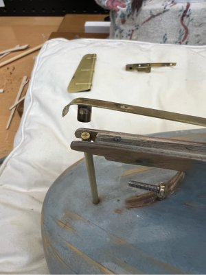
In this case the bush has been soft soldered to the brass strip, rather than glued, and the strip has been attached with M1 x 10mm stainless screws that are tapped into holes filled with set epoxy (ie, the holes are drilled out to a larger size, filled with epoxy, then re-drilled for the screws) to stop potential rot. The changed design is simpler, neater and stronger. I don’t mind re-working things when that’s the outcome.
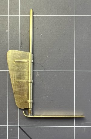
To finish things off, the rudder blade needs to be filled so that I don’t have to be concerned about it filling with water, and then attached to the rudder post. I mixed up a small batch of the epoxy I’ve been using for coatings and managed to inject that into the blade while held sideways and blade down…leaving just enough room to be able to easily slide the post in later. This was allowed to set overnight (no leaks, so the solder job must be okay). Then next day glued the blade and post together using a product named Plastibond that I already had in the workshop. It’s an old product, just a polyester resin with filler that makes up a thick paste that is easy to deal with and sets in 20-30 minutes. Here is the finished rudder and its mount ready for painting…the blade will be painted the lower hull colour, and the post will be left as bare greased brass.
You may remember back toward the start of this project (post #6 to #8), that I decided to replace the simple sheet ply and dowel arrangement for the rudder due to this build being for RC. Instead, everything was made in brass but I only got to the stage of bending and shaping the rudder, but not finishing it and attaching it to the rudder post. First, I need to join and seal the rear edge of the bent sheet brass rudder blade, then fill the interior void of the rudder with epoxy resin, and glue it to the rudder post.
To join the rear edge, I decided to soft solder this join. The brass sheet is very thin (0.5mm) and I don’t fancy heating that to brazing temperatures with a flame. The inside is eventually going to be epoxy filled, so a soft soldered joint will be plenty strong enough. The area to be soldered was sanded to give a nice bare edge, then thoroughly degreased, and fluxed with an electronics flux solution. My usual soldering iron is too fine for this sort of work, so I thought that I’d try the trusty Makita hot air gun (~600C at max setting). The rudder was propped up in a few bulldog clips to hold the edges closed and heated. It didn’t take too long to get up to temp and the solder wicked into the joint as you would hope. A bit of cleaning with fine grit paper and steel wool and it looks good.
The straps around the rudder (2mm wide strips of brass) were cleaned up and these were attached using thin CA to wick into the joint…that worked really well (except for also joining a few fingers together! The fine nozzle extension had split, and I didn’t realise). I hadn’t used thin CA before…near instant bite and great wicking ability. I wouldn’t use it everywhere, but good for this job.
Alright, before gluing in the rudder post I’d better run some checks on the hull, as it hasn’t been inserted in the completed form. Does the rudder move freely?, and does everything fit in when installed from below as planned? Well…that’s a no and a no.
The rudder movement is being constrained by the hull. This was first tested months ago when the hull was just at keel stage, no frame or planking…now the top edge of the rudder blade was being stopped short by the ‘fuller’ hull surface. This was a simple fix, just re-profile the shape so that it will turn from side to side. It will now go almost 90 deg in either direction.
Next, the bottom mount that I had previously built works fine when you are just testing it with the free rudder post, with no rudder attached. However, when the rudder is fixed to the post, the shaft cannot slide up far enough into the hull to fit the bottom of the shaft into my fabricated lower bush. So, back to the drawing board…and a much simpler solution now presents itself.
To refresh your memory without having to dredge back through the log, here is the existing design…the bottom end of the rudder post sits in a short piece of brass tube that is epoxied inside a shaped bent brass strip.

The problem is that the bottom of the keel now has the two cheeks shown (labelled 17 in the photo) glued in place and they prevent the lower bush being manoeuvred into place without deforming the strip and popping the epoxied bush off the strip. As it turns out, a better solution was already looking at me…I had since put a heavier brass strip over the bottom of the existing thin strip as protection from bottom strikes and general wear and tear. All I had to do was remove the existing set-up, and then fix the tubular bush to the heavier strip that attaches from below instead.
Now when the rudder and its post are fitted as a single assembled piece (sorry, that’s not how it’s shown in the photo) from below, and the lower bush can be slipped over the exposed rudder post end and the strip screwed to the lower face of the keel.

In this case the bush has been soft soldered to the brass strip, rather than glued, and the strip has been attached with M1 x 10mm stainless screws that are tapped into holes filled with set epoxy (ie, the holes are drilled out to a larger size, filled with epoxy, then re-drilled for the screws) to stop potential rot. The changed design is simpler, neater and stronger. I don’t mind re-working things when that’s the outcome.
To finish things off, the rudder blade needs to be filled so that I don’t have to be concerned about it filling with water, and then attached to the rudder post. I mixed up a small batch of the epoxy I’ve been using for coatings and managed to inject that into the blade while held sideways and blade down…leaving just enough room to be able to easily slide the post in later. This was allowed to set overnight (no leaks, so the solder job must be okay). Then next day glued the blade and post together using a product named Plastibond that I already had in the workshop. It’s an old product, just a polyester resin with filler that makes up a thick paste that is easy to deal with and sets in 20-30 minutes. Here is the finished rudder and its mount ready for painting…the blade will be painted the lower hull colour, and the post will be left as bare greased brass.

Painting the lower hull
Finally, I hear all say…it does seem to have taken a while to get here. So, what colours will be used? I like the colour used on the hull of Billing’s example model…above the waterline. I call it duck-egg blue, a very light blue. I’ll be painting the hull using rattle spray cans, and I was lucky enough to find a very good match to that colour. It is from the Montana Gold brand range, and it’s called Polar Blue. These paints are rated for indoor/outdoor, and it will be getting an acrylic exterior clear matt coat later as well.
But the lower hull, below the waterline, was a minor problem for me colour-wise. I didn’t like the dark brown as used in Billing’s example and I was considering a rusty red at one point, but they didn’t seem appropriate for a timber vessel and would have detracted from the subtle upper hull. In the end I settled on a dark-ish grey, it looks good against the upper colour and provides a purposeful looking base to the boat when she is out of the water. Finding the right grey, in a spray can, was a bit of a challenge (I now have a selection of cans in the workshop for future jobs!) but I settled on a White Knight Rust Guard colour called ‘Ironstone’…that’s a standard Colorbond colour (they do metal roofing in Aus). All through the painting process I kept a small piece of offcut pine (about 150mm square) that I sprayed each filler/primer/colour onto before I started to coat the boat. It was good for checking colours, but importantly I could check that the paint chemistry of each coat wasn’t going to cause a problem with the layer beneath (cracking, wrinkling etc)…they’ve all been okay so far.
The hull was given a good wash to remove any contaminants and wiped with turps on a clean rag (recommended on the can). We’re doing the lower colour first, so the hull was inverted and sprayed on a warm spring day. It sprayed very nicely from the can, so I’m happy with the job. It looked very glossy while wet but dries to a nice satin finish. I let it sit overnight and gave it a second coat next day, also without any problems.
It looks a bit ‘orange-peel’ when freshly sprayed, as in the photo below, but that settles out and it dries very smooth…
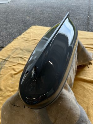
I decided to let it dry and harden up for a few days before marking the waterline and adding masking tape etc. While that was happening, I built a simple cradle (shown in a future post) and at one point I had the hull sitting in the cradle with cloth between the surface and the four weight bearing points for an hour or so…oops. Even though everything seemed nice and cured, I ended up with four imprints of the fabric weave in the paintwork. I was not impressed! But, with these things you just have to turn around and set it right. The surface was lightly wet sanded with 600 grit to remove the imprints, and the entire surface was recoated…I also extended the paint a little further down the sides as the trial watermark showed that I had only just covered. It.
Now this time I’ll give it a little longer to cure and I’m giving it some short bursts out in the morning sun to get a bit of UV and mild warmth to help the curing process (the paint is designed for touch ups on metal roofing). This has also allayed any fears about how the hull would fare in warmer weather after the problems I’d had earlier with plank separation…very pleased to see that it seems rock solid.
The log is being written close to real-time at the moment, so if everything dries off okay, next time we will be masking-off and painting the hull above the waterline.
Finally, I hear all say…it does seem to have taken a while to get here. So, what colours will be used? I like the colour used on the hull of Billing’s example model…above the waterline. I call it duck-egg blue, a very light blue. I’ll be painting the hull using rattle spray cans, and I was lucky enough to find a very good match to that colour. It is from the Montana Gold brand range, and it’s called Polar Blue. These paints are rated for indoor/outdoor, and it will be getting an acrylic exterior clear matt coat later as well.
But the lower hull, below the waterline, was a minor problem for me colour-wise. I didn’t like the dark brown as used in Billing’s example and I was considering a rusty red at one point, but they didn’t seem appropriate for a timber vessel and would have detracted from the subtle upper hull. In the end I settled on a dark-ish grey, it looks good against the upper colour and provides a purposeful looking base to the boat when she is out of the water. Finding the right grey, in a spray can, was a bit of a challenge (I now have a selection of cans in the workshop for future jobs!) but I settled on a White Knight Rust Guard colour called ‘Ironstone’…that’s a standard Colorbond colour (they do metal roofing in Aus). All through the painting process I kept a small piece of offcut pine (about 150mm square) that I sprayed each filler/primer/colour onto before I started to coat the boat. It was good for checking colours, but importantly I could check that the paint chemistry of each coat wasn’t going to cause a problem with the layer beneath (cracking, wrinkling etc)…they’ve all been okay so far.
The hull was given a good wash to remove any contaminants and wiped with turps on a clean rag (recommended on the can). We’re doing the lower colour first, so the hull was inverted and sprayed on a warm spring day. It sprayed very nicely from the can, so I’m happy with the job. It looked very glossy while wet but dries to a nice satin finish. I let it sit overnight and gave it a second coat next day, also without any problems.
It looks a bit ‘orange-peel’ when freshly sprayed, as in the photo below, but that settles out and it dries very smooth…

I decided to let it dry and harden up for a few days before marking the waterline and adding masking tape etc. While that was happening, I built a simple cradle (shown in a future post) and at one point I had the hull sitting in the cradle with cloth between the surface and the four weight bearing points for an hour or so…oops. Even though everything seemed nice and cured, I ended up with four imprints of the fabric weave in the paintwork. I was not impressed! But, with these things you just have to turn around and set it right. The surface was lightly wet sanded with 600 grit to remove the imprints, and the entire surface was recoated…I also extended the paint a little further down the sides as the trial watermark showed that I had only just covered. It.
Now this time I’ll give it a little longer to cure and I’m giving it some short bursts out in the morning sun to get a bit of UV and mild warmth to help the curing process (the paint is designed for touch ups on metal roofing). This has also allayed any fears about how the hull would fare in warmer weather after the problems I’d had earlier with plank separation…very pleased to see that it seems rock solid.
The log is being written close to real-time at the moment, so if everything dries off okay, next time we will be masking-off and painting the hull above the waterline.
Painting the lower hull
Finally, I hear all say…it does seem to have taken a while to get here. So, what colours will be used? I like the colour used on the hull of Billing’s example model…above the waterline. I call it duck-egg blue, a very light blue. I’ll be painting the hull using rattle spray cans, and I was lucky enough to find a very good match to that colour. It is from the Montana Gold brand range, and it’s called Polar Blue. These paints are rated for indoor/outdoor, and it will be getting an acrylic exterior clear matt coat later as well.
But the lower hull, below the waterline, was a minor problem for me colour-wise. I didn’t like the dark brown as used in Billing’s example and I was considering a rusty red at one point, but they didn’t seem appropriate for a timber vessel and would have detracted from the subtle upper hull. In the end I settled on a dark-ish grey, it looks good against the upper colour and provides a purposeful looking base to the boat when she is out of the water. Finding the right grey, in a spray can, was a bit of a challenge (I now have a selection of cans in the workshop for future jobs!) but I settled on a White Knight Rust Guard colour called ‘Ironstone’…that’s a standard Colorbond colour (they do metal roofing in Aus). All through the painting process I kept a small piece of offcut pine (about 150mm square) that I sprayed each filler/primer/colour onto before I started to coat the boat. It was good for checking colours, but importantly I could check that the paint chemistry of each coat wasn’t going to cause a problem with the layer beneath (cracking, wrinkling etc)…they’ve all been okay so far.
The hull was given a good wash to remove any contaminants and wiped with turps on a clean rag (recommended on the can). We’re doing the lower colour first, so the hull was inverted and sprayed on a warm spring day. It sprayed very nicely from the can, so I’m happy with the job. It looked very glossy while wet but dries to a nice satin finish. I let it sit overnight and gave it a second coat next day, also without any problems.
It looks a bit ‘orange-peel’ when freshly sprayed, as in the photo below, but that settles out and it dries very smooth…
View attachment 483050
I decided to let it dry and harden up for a few days before marking the waterline and adding masking tape etc. While that was happening, I built a simple cradle (shown in a future post) and at one point I had the hull sitting in the cradle with cloth between the surface and the four weight bearing points for an hour or so…oops. Even though everything seemed nice and cured, I ended up with four imprints of the fabric weave in the paintwork. I was not impressed! But, with these things you just have to turn around and set it right. The surface was lightly wet sanded with 600 grit to remove the imprints, and the entire surface was recoated…I also extended the paint a little further down the sides as the trial watermark showed that I had only just covered. It.
Now this time I’ll give it a little longer to cure and I’m giving it some short bursts out in the morning sun to get a bit of UV and mild warmth to help the curing process (the paint is designed for touch ups on metal roofing). This has also allayed any fears about how the hull would fare in warmer weather after the problems I’d had earlier with plank separation…very pleased to see that it seems rock solid.
The log is being written close to real-time at the moment, so if everything dries off okay, next time we will be masking-off and painting the hull above the waterline.


