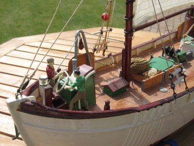
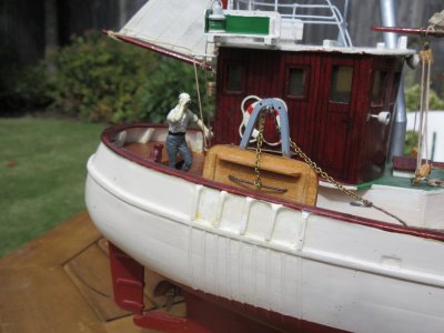
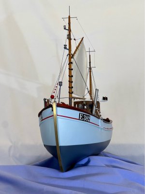
Mary Ann by Billing Boats 472 - COMPLETED

Forward deck fittings
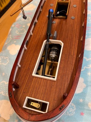
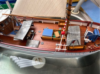
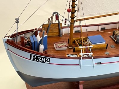
The forward deck area has several fixtures like an on-deck anchor locker, companion way, and a trawling light on a pole. In this case, I decided to have a working trawl light, so the electrical feed was installed before the hull was fully planked and the lantern and its pole were constructed differently to the plan. This was described in detail in earlier posts (post #36), but the main difference is that it has a brass tube for the pole instead of a piece of dowel…this conceals the wiring.

I made a few subtle changes to hide the wiring…there is an additional block of wood at the foot of the light post (the plan has the pole directly attached to the deck) and this has a hidden pathway underneath for the wiring, and a short piece of plastic tubing joins that block and takes the wiring through the anchor locker, like a conduit, and under the next fixture and into the companionway where the electrical feed comes above deck. In the following photos you can see the wire path through the conduit and the sections cut from the base of the companionway to allow the wires to sit underneath.
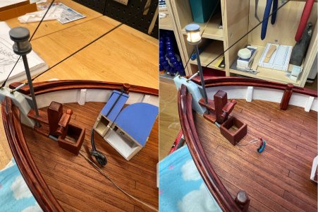
1746854165767.jpeg

The light is ‘on’ in the right hand shot…always test before gluing things down, right? Yeah, well, it wasn’t until a few days later when I was demo’ing progress to the Admiral when I noticed that the trawl light was significantly brighter than all the other lighting. Hmmm, I think I forgot to add the current limiting resistor!! Luckily the LED didn’t let go.

I had two choices…remove the companionway (glued to the deck with a spot of CA and white glue) or hope that the internal wiring had enough length to allow me to add the resistor inline inside the main hold. I didn’t fancy removing the building…adding any sort of solvent, even carefully applied, was likely to upset the finish on the deck (and hence me!). So, it was time to test my philosophy of making the electricals accessible and removable if needed. Things went well and the job was done in less than hour and everything back in place and working.

Shroud pin rails
Fiddly job…very fine timber used here, tiny hole at each end, difficult to paint neatly, then they are attached by tying a fine rope between the holes in each end. I also added a spot of CA to make sure they stay in place. For this boat, they are mainly used to hold the extra gear used during fishing…float on one side and a pike pole on the other, and a piece of timber that I’m not sure of its use except maybe as a fairly large pin to store spare rope on?
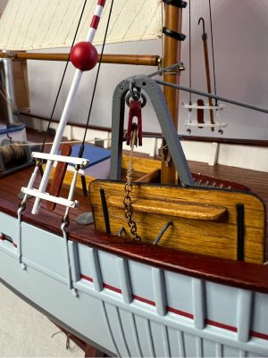
1746854317962.jpeg

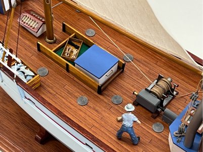
Forward trawling gear and the winch
The trawling gear, otter boards and their gallows, were put together way back in post #54. I’ve left installing these until almost last as they are in a vulnerable spot and likely to get knocked about during construction, plus the fore and aft sets have a rope line permanently run to the central winch. In the photos on the box, the forward running line is under tension, ie suspended above the deck, so that would have got tangled in something for sure. The forward boards and gallows can be seen in the photo above.

The winch is made up from a set of mainly brass parts…some punched sheet, some nicely machined pieces and a few pieces of wood. Its construction was described in post #31. The spools of each side of the winch hold a reasonable length of rope, and I don’t want to ‘waste’ that much of my scale rope, so I decided to use some of the kit-supplied rope to fill the bulk of the spool and then I just put the final two layers of the scale rope on over that. I’m using 0.7mm rope for this, that would scale to 23mm…sounds about right to me. The two spools can be removed from the body of the winch as I haven’t glued the end capstan to the shaft, this makes it much easier to wind the rope onto the spool. Don’t forget that it needs to be wound in opposite directions for each side, to match the direction that the rope needs to pull from. After getting everything in place, I then gave the two spools of rope a light soaking with thin CA to lock it all in place. The body of the winch was glued to the deck using epoxy glue.
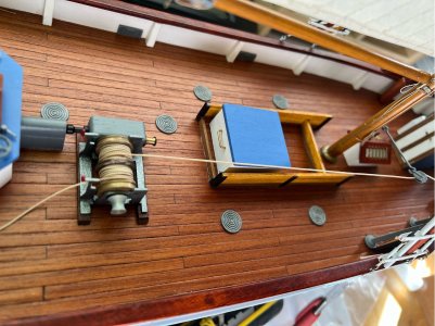
1746854561295.jpeg

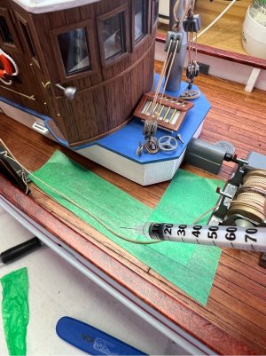
While the forward rope is under light tension and runs overhead, the rope that goes to the aft gallows is left loose on the deck. To ensure that this stays in place and lays along the deck, I carefully wet the rope with thin CA (using a fine syringe) while holding it in place. I protected the deck with masking tape because I didn’t want to stick it down, just make it stiff. This has worked out well, it looks natural but doesn’t get caught up in anything.
1746854662758.jpeg

Next time a few finishing touches aft of the wheelhouse.
 
Just a few tasks to finish at the aft end…

Aft Sail
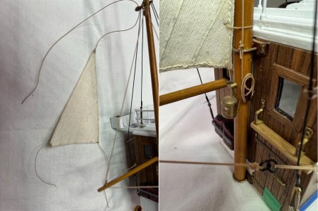
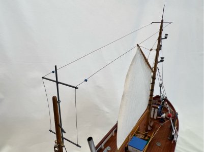
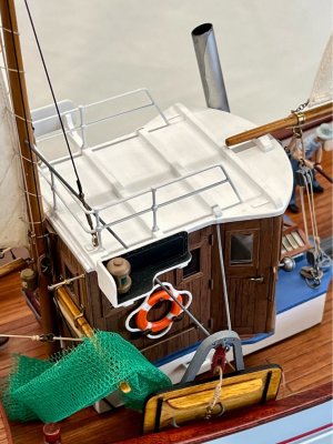
There is a small mast connected to the rear of the wheelhouse. As described in an earlier post, I have made a few small mods to this mast so that it is now connected to the wheelhouse only (not the main deck) so that everything can be lifted off the deck in one piece without having to muck around with the rigging. The sail is simply rigged, a sheet at each corner and the luff secured with a spiral of rope up the mast. I used 0.5mm rope for all of those…

1747459517574.jpeg

Aft trawling gear
The gallows and otter board at this end are similar to the those on the foredeck. The only difference to the kit is that I have decided not to permanently install the metal rod stays on the gallows. These attach overhead on to the wheelhouse and the aft mast, but they will be a problem when or if I need to remove the wheelhouse. I’ve made the rods and painted them, and you will see them in the final photos, they just won’t be left in place for usual operation.


Fish nets
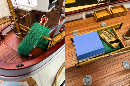
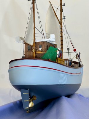
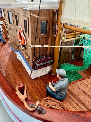
The kit provides a sheet of tulle fabric to be fashioned into a net. It is bright green and made of a plastic material, so is probably a reasonable approximation of a net. The photos of the model show it used in two areas…a large piece hanging from an arm at the back of the wheelhouse, and another folded piece in the fenced area just aft of the main mast. I cut the sheet in half lengthwise, then folded one piece down to about 20mm wide and used my hot air gun to warm it up and ‘set’ the folds in the fabric. It was then easy to arrange over the arm and again heat it so that it would hold the shape without unfurling. I did something similar to the piece that sits under a wooden box over the cover to the forward opening in the deck. In the latter case, I cut the net just a little bit too big for the side of the cover…this allows it to grab the surrounding fence as it is put in place and helps to hold it in place. The box sitting on top holds a few hocks of rope that I created using ‘the fork’ method described recently in another post - using the tines to wrap the rope around and tie off, it makes the job much simpler.

A photo with both areas of netting…
1747459729294.jpeg

Next up is the cradle.
 
The Cradle
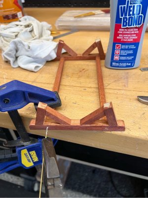
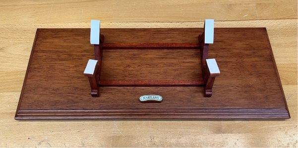
I haven’t bothered with the cradle up to this point, as I do all my work on the hull using a soft old pillow on the bench, I find it holds the hull well and it’s easy to position the boat at whatever angle is needed, without fear of marking the hull surface. But I’m at that point where I need something to stand the boat on. The instructions do have a plan for a simple stand, which I’ve changed a little. The plan is very simple and looks quite light weight, almost fragile in the stays that it uses. So, I decided to beef it up a little by using heavier sections and solid members for stays. The extra timber is Paulownia (mentioned earlier), and although it has a light natural colour, it takes a stain very well and has a good, lightly grained surface. I gave all surfaces, except the small sections that would be glued, a coat of the stain finish before putting it together…so that I didn’t have to be concerned with glue marks preventing stain uptake.

All members are butt joined and glued and then after drying, the important joints were pinned with brass wire to give a bit more strength. This is just 1.18mm wire pushed into 1mm drilled holes, the wire was sharpened on one end and coated in glue and forced in with pliers until it bottomed. They were finished off by first cutting off the excess with side-cutters and then filed smooth. The small, exposed brass tops look quite nice against the stained wood.

Here is one of the brass pins being glued into the frame…

1747460041345.jpeg

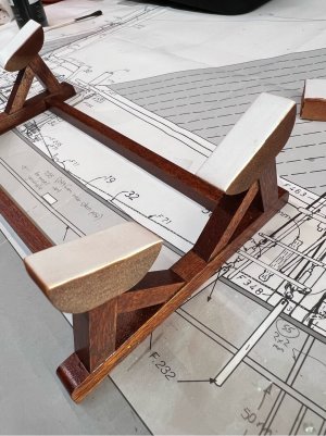
The geometry of the stand is similar to the plan, although I made mine a touch longer, so the mounts sit just outside the scuppers at each end, I think it looks a little better balanced. I’ve also made a change to the contact points to make sure that I don’t get rub marks or imprints from it sitting on a small contact area for long periods. I looked around the workshop and found some fine, closed cell foam…the sort of thing that you might get packed around equipment (similar to the foam you often see in running shoes these days). I shaped the blocks with a knife and then finished them with a fine paper on the mini disc sander. I was a bit concerned about the blocks being white against the dark stain of the cradle, so I had a go at using the stain on it…and it takes it perfectly, it was even happy to have a spray coat of matt acrylic without having any noticeable effect on its cushioning. They are attached to the cradle using double sided tape.

1747460187212.jpeg

It’s interesting that the cradle used in the official photos on Billing’s Google Photo drive is not the same as the one described in their plans, it is a much fancier version.

Next time we're back on something more exciting...re-installing the prop and rudder.
 
Hello you have made a very nice job of the model. I run 2 radio control Mary Anns one I bought, which was built as a static model and I converted her. Mostly worked but static builders are not good at planking to keep the water out! This was resolved eventualy. There could be a problem with the suggested construction and that is the sealed bulkhead at the bow. My model took on a mysterious leak which was at the bow and into the sealed off area. I have since managed to open up this space, in the end having to buy a flexible drive for my Dremel drill to blindly drill and sand away a hole. Then of course waterproofing this area! I poured in 50 ;50 varnish and thinners sealed it off and shook it about a lot. Then careful checking of the planking joints. I bright light poked into the blocked off area and a darkened room helped this. Now all is well.

I have some poor photos of these fishing boats printed in a Naval Intelligence book for wartime use for British Naval vessels when querying fishing boats in the North Sea. It looks to me that the winch on board should be at right angles to the Billing plan. Logical when you look at the position of the trawl boards. By the way the red and white buoy is not a safety buoy but part of the system of fishing and it marks where the net is first dropped into the sea, the boat then circling round to form a curve to position the net so that it catches the out-going tide. The stay sail at the stern keeping the fishing boat stable usually in the off-shore wind. It was engines off and a 4 hour wait for the tide.

During WW2 the boats had to be painted white and there was supposed to be a German soldier on board when off to fish, the fish were mainly then exported into Germany. But the unexpected result was the enormous reduction in fishing and the recovery of the herring population known as the "silver darlings" during the hostilities.

There is a film called "Suicide Mission", shown now and again on cable TV, where these fishing boats are featured as they were part of the Shetland Express when smuggling people across the North Sea. The main thing to take away from it is the noise of the engine, the boats were heard long before they were seen! A loud version of the canal narrow boats "potato engines".

The plastic kit market has many figures available in this scale and both my boats are manned. Father and 2 sons is an option!
The 385 motor you have is quite powerful enough and 6 cell NiMh or (2S) is quite enough. I used very cheap esc's with built in BEC, from AliExpress, they are tiny units just a pcb with shrink wrap cost about GBP2.50. Never had one fail and use a lot. In case you do use one, note the incredibly tine slide switch which turns the brake on and off for model cars.

The kit has been in constant production since 1958 and must be among the most prolific ever.
What a shame the St. Roch kit was not constructed in the same way! Billing missed out big time on that, looks like a model aeroplane designer planned that and to mind "screwed up" as many of my friends took one look at the non-nautical design and passed it by.


regards

Roy
 
Hello you have made a very nice job of the model. I run 2 radio control Mary Anns one I bought, which was built as a static model and I converted her. Mostly worked but static builders are not good at planking to keep the water out! This was resolved eventualy. There could be a problem with the suggested construction and that is the sealed bulkhead at the bow. My model took on a mysterious leak which was at the bow and into the sealed off area. I have since managed to open up this space, in the end having to buy a flexible drive for my Dremel drill to blindly drill and sand away a hole. Then of course waterproofing this area! I poured in 50 ;50 varnish and thinners sealed it off and shook it about a lot. Then careful checking of the planking joints. I bright light poked into the blocked off area and a darkened room helped this. Now all is well.
Hi Roy,
Thanks for the kind words and the added info. It's always interesting to hear about how they were worked...I wasn't sure whether the sails were actually used, but your explanation makes sense.

I did take extra care with waterproofing in that front, sealed space...similar to your fix, I put plenty of epoxy in there before sealing down a few holes I had put in the false deck. I also have the protection of an external fibreglass layer, so it should be okay.
 
Re-installing the rudder and propellor
I’ve been looking forward to this step for some time. I had left them off while I was still working on the hull as I like using a pillow as my dock and I didn’t want to accidentally put side forces on the rudder while I’m working on other things.

The prop shaft thread had been protected during painting, but I still managed to fill the thread sufficiently to prevent the lock nut from being threaded on. I cleared that by very carefully running the motor back and forth while holding a fine blade against the thread…cleared in no time, and fingers still intact! (I wasn’t so lucky while cooking the other night). So, I now have a nice shiny brass prop on the model, and it looks great…it is a three blade, and I’ve been told that it really should be a two blade, but I’m going to overlook that fact.

The rudder was a little trickier, just because of the confined nature of this build. The rudder has been mentioned a couple of times on the way through the build. It is a rebuild of the kit’s rudder in brass (kit was wood and fixed in place) and has a working post that penetrates the hull and is connected to a servo via a fabricated horn. The rudder did look very nice in its naked satin brass sheet, but it didn’t look like any pictures of fishing boats that I’d seen, so it has been painted in the same grey that the lower hull is painted and only the straps have been left ‘brass’…that was initially un-planned, but I accidentally scratched the paint off one during a test fitting and thought that it looked too good, so I modified all three and have clear coated it all in matte clear.

To install, I cleaned out the rudder tube and greased the post with a waterproof grease and inserted that from below (the rudder and its post are glued together as a single piece, it was built right back at the start in post #6). The lower post bush and its holding plate was installed below the keel…this is an area that had a mid-build design change in post #98. It looks and feels good.

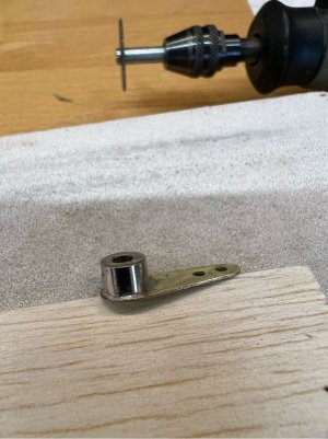
Up top, I had a few issues with the installation of the control horn on the top of the rudder post. This is a cylindrical collet with a hex drive grub screw that I had epoxied to a piece of brass sheet, to form the horn. First challenge was the small grub screw was proving to be challenge to tighten now the deck was in place. Fortunately, I have a really good set of fine drivers (IFixIt brand…recommended) and it has a long flexible drive, so I can get access to the screw through the large opening under the wheelhouse. Then, while testing the grip of the horn to the rudder post, I found that epoxy doesn’t stick well enough to shiny nickel-plated brass for this task…but it was good to find this now rather than out on the water.

So, the fitting came out and I went and had a cup of tea… Okay, I decided to crenelate the top of the brass collet with a Dremel cutting disc (the grooves will help hold the solder), and really rough up the base of the brass horn, then soft solder them together. I would have preferred the gold-standard of silver solder…but I don’t have a small torch at the moment. I got good heat into the collet and, with some flux, was able to wet the surface and fill the new grooves…also tinned the horn nicely and then soldered the two together. Some may want to argue it, but the joint feels sound, and I’m sure that it is stronger than the plastic horn (supplied) that is used on the servo end of the connecting rod.

1747530464225.jpeg

I also made sure that when I was doing the soldering, the grub screw was orientated to aim at the direction of the main hull opening to suit the flex driver (shown below engaged in the grub screw).

1747530505929.jpeg

After adding the plastic horn to the servo, I noticed that the control rod would just shave the bottom of the coaming…it wasn’t binding or slowing anything, but I though it best to remove a little wood from the bottom of the coaming to make sure it doesn’t cause problems later.

1747530531075.jpeg

Job finished. The rudder has 55 degrees swing in each direction

1747530564234.jpeg

Looks great from that angle. Next up we will see if she floats.
 
Last edited:
Hello Peter, your Mary Ann looks pristine, I would think in the real world that would have only lasted a month or two as the odd photo I have of them shows the boats in a rather dilapidated state. There was often a small rowing boat carried on board at the stern and I have been pondering where to fit that in. Glad to see you have a 9gram servo for the rudder as not much effort is required. You will need a fair bit of ballast to take her down and with a model this size I put ballast at the bow and stern as this stops her bobbing around on the water. With ballast centrally placed the movement is exagerated like a see saw.

The reason I have 2 of them is that I wanted to run them both together from a 4 ch. RC with each model having a 4 ch. rx installed but using a different pairing of the connections, so that my Tx had the left stick for one boat and the right stick for the other. My right hand is trained to do this already but my left hand is at 'boat handling 101' and the first time out was a failure, the main outcome was to fit a bumper on the bows!

The pictures show the 2 crew stowing the anchor gear on leaving port. The other is the captain looking out for sea birds to help find a shoal of fish.
You can just see that my access hatch is large as experience has shown that getting a hand inside is often needed. I also made a brass rudder. I use NiMh cells and these models both run on sub-C 7.2 volts, the battery is divided into 2 pieces with 3 cells each across the keel under the mast. I am expecting some 2800mAh cells soon to make up into batteries and these are 4/5 sub-C and will be a better fit between the bulkheads. I bought a mini-welding set to make up bespoke batteries to fit different models, together with battery shrink wrap to hold them together. My RC goes back many years and I still use 27Mhtz and more modern 40 FM, but as I have well over a dozen sets I shall not go ob=ver to 2.4Ghtz.

I was not all that far from you earlier in the year staying with our son in Woy Woy, he is model railways, but full size for sailing. I go every year for 5 weeks or so starting late January, must have been about 15 times now. We went to the Air Show near Newcastle this year, excellent show but rather hot for me! Last year we were at Maitland for the Bayer-Garret loco trip.
regards
Roy

IMG_1644 - Copy.JPG

IMG_1647.JPG
 
Hi Peter I keep meaning to fit registration numbers and my Naval Intelligence book has genuine numbers and names for the time, so will get there eventually. I find deck planking difficult to look right. I now scrape (not sand) deck planks and use a cloth wrapped around a finger to put varnish on as this stops the varnish following the grain of the wood. As far as the wood goes the surface usually ends up a grey colour.
In the meantime I am building a small sailing boat called Wild Swan.
Roy
 
Last edited:
Hello Peter, your Mary Ann looks pristine, I would think in the real world that would have only lasted a month or two as the odd photo I have of them shows the boats in a rather dilapidated state. There was often a small rowing boat carried on board at the stern and I have been pondering where to fit that in.

The reason I have 2 of them is that I wanted to run them both together from a 4 ch. RC with each model having a 4 ch. rx installed but using a different pairing of the connections, so that my Tx had the left stick for one boat and the right stick for the other. My right hand is trained to do this already but my left hand is at 'boat handling 101' and the first time out was a failure, the main outcome was to fit a bumper on the bows!

regards
Roy
Hi Roy, yeah, you're right about looking too clean and fresh...I decided early on that because this was my first boat, I wouldn't worry about trying to get an age weathered finish, it was an extra complication that I didn't need at the time. So I just think of her on her maiden voyage.

I gotta say that I admire your determination to try to master two boats at once...that's got to be great for keeping your mind exercised. I was having enough trouble the other day with one boat in the our pool...I just have to remember that I'm behind the wheel when she is travelling toward me. Must be tricky when you've got your two boats travelling in different directions.
 
Tub test and ballasting
Well, it’s time to put her in a test tub to see how she floats…the hull has not been wet at all so far. This is an area that is not covered at all in the kit plans as it is designed as a static model, so I’ll add a bit of detail for anyone building it as an RC model.

I haven’t done any ballasting of any kind during the build, so this might get a bit messy first time out. And, although I have a nice sized body of water in our backyard…ie, the swimming pool, I thought it might be best to go with the laundry tub for the first test, just in case.

I filled the tub to almost the top lip so that I could get a good view of the waterline. And what do know, she floats…a little high, and lists a little to port, but she is quite stable. Such a good feeling!

1747976445405.jpeg

My plan is to use sheet lead as ballast. I have some left over from some roof flashing that had been removed. This was cut into strips about 40mm wide (fits easily between the bulkheads) and 100mm long.

Here is a photo of the lead sheet sitting on the deck, with the waterline close to where I want it. The small amounts on the starboard deck in front of the winch are to counter the slight list. The total weight of ballast is about 500g of lead. The long sheets were folded in half and hammered flat before installing…makes it easier to get them in and to fit on either side of the keel timbers. They were painted a dark metallic charcoal colour before gluing them in place with silicone glue.

1747976547754.jpeg

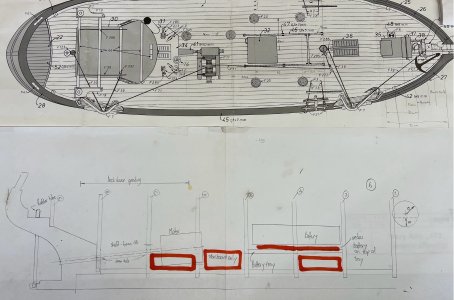
In the rough, side-view below (drawn ages ago when I was working out the prop shaft placement) with the red marker showing which compartments were used for the ballast. The ones between bulkheads 3 & 4 and 6 & 7 were placed as close to the keel as possible on each side. The one between 5 & 6 was on the starboard only and it was placed a bit higher on the wall to enhance its righting effect. The straight line drawn under the battery is where I put the lead on top of the battery tray, under the battery itself…it was just easier given how crowded it is in that area.

1747976646917.jpeg

Here’s a finished one in the 6 – 7 area beside the motor.

1747976720156.jpeg

She needs to go back in the water to double-check that it is all okay now that it has been installed. Some of the forward ballasting went in one bulkhead further aft than I had it in my tub test, because it was easier to install in that area (under the battery) than between bulkheads 2 & 3. Total finished weight of the boat, with battery etc is 1.89 kg…I was sure it would be heavier than that, it feels nice and solid in your hands, but there you go.

And here she is in the water doing a second test…on a beautiful late autumn day. The stern sits right on the waterline, there is no list to either side, and the bow is probably 5mm high, but I think I’ll leave it as is. She also handles nicely, even in the confines of the pool, provided there is some water being pushed past the rudder. The battery and motor combo, although not particularly powerful, is capable of pushing her along at well over scale speed. I’ll get a video posted at some point.

1747976886536.jpeg

Just a couple of small jobs to finish her off…the crew, the fish, and a stand for the cradle, and then were ready for final photos.
 
Hello Peter, all looking good. Maybe 50 years ago I bought the Billing shrimp boat Cux 87 kit very cheap around £6.00 in a sale but I preferred the Mary Ann and there was a fittings kit for for Mary Ann again in a sale in the local Beaties model shop also about £6.00. I put the frames together but never got round to planking the model as the wood was so awful and I still have her in that state.
Just 2 years ago in our club auction there was what looked like a complete Mary Ann unbuilt kit. I bid for it and it was knocked down to me for £10!
When I looked at it in detail I found the hull wood sheets were missing! I wondered if my Shrimp boat hull would work? I did some checking up on the Internet and Billing kits web site and identified the wood sheet numbers for Mary Ann and then went to the Cux wood sheet numbers. They are the same! So I have another Mary Ann waiting to be made. But she is in the queue with 5 other kits. Here in the UK there is not much of a market for kits as with the demographic situation a lot of the prolific modellers have either died or are no longer able to persue the hobby and there are more than a few working models for sale.
However ability in construction and quality of finish and paintwork can leave a lot to be desired so they need a careful look before purchase. In our club (St. Albans model engineering society), check out our web site. I am the one who tries to dispose of models and also donated ones. I have a complete unstarted and now rare kit of the Wedico Inga IV sailing yacht, but no takers. I have my own one which I restored 20 years ago, always a crowd puller.

Have you got an eye out for your next build? The general scale of Mary Ann is good for figures (crew) and the ones I like are the Airfix ones with separate limbs and torso etc as they go together in any way you want. I see your crew member as dressed for the summer, on the North Sea everyone is wrapped up in oilskins to keep dry!

Roy
 
Tub test and ballasting
Well, it’s time to put her in a test tub to see how she floats…the hull has not been wet at all so far. This is an area that is not covered at all in the kit plans as it is designed as a static model, so I’ll add a bit of detail for anyone building it as an RC model.

I haven’t done any ballasting of any kind during the build, so this might get a bit messy first time out. And, although I have a nice sized body of water in our backyard…ie, the swimming pool, I thought it might be best to go with the laundry tub for the first test, just in case.

I filled the tub to almost the top lip so that I could get a good view of the waterline. And what do know, she floats…a little high, and lists a little to port, but she is quite stable. Such a good feeling!

View attachment 521371

My plan is to use sheet lead as ballast. I have some left over from some roof flashing that had been removed. This was cut into strips about 40mm wide (fits easily between the bulkheads) and 100mm long.

Here is a photo of the lead sheet sitting on the deck, with the waterline close to where I want it. The small amounts on the starboard deck in front of the winch are to counter the slight list. The total weight of ballast is about 500g of lead. The long sheets were folded in half and hammered flat before installing…makes it easier to get them in and to fit on either side of the keel timbers. They were painted a dark metallic charcoal colour before gluing them in place with silicone glue.

View attachment 521372

In the rough, side-view below (drawn ages ago when I was working out the prop shaft placement) with the red marker showing which compartments were used for the ballast. The ones between bulkheads 3 & 4 and 6 & 7 were placed as close to the keel as possible on each side. The one between 5 & 6 was on the starboard only and it was placed a bit higher on the wall to enhance its righting effect. The straight line drawn under the battery is where I put the lead on top of the battery tray, under the battery itself…it was just easier given how crowded it is in that area.

View attachment 521373

Here’s a finished one in the 6 – 7 area beside the motor.

View attachment 521374

She needs to go back in the water to double-check that it is all okay now that it has been installed. Some of the forward ballasting went in one bulkhead further aft than I had it in my tub test, because it was easier to install in that area (under the battery) than between bulkheads 2 & 3. Total finished weight of the boat, with battery etc is 1.89 kg…I was sure it would be heavier than that, it feels nice and solid in your hands, but there you go.

And here she is in the water doing a second test…on a beautiful late autumn day. The stern sits right on the waterline, there is no list to either side, and the bow is probably 5mm high, but I think I’ll leave it as is. She also handles nicely, even in the confines of the pool, provided there is some water being pushed past the rudder. The battery and motor combo, although not particularly powerful, is capable of pushing her along at well over scale speed. I’ll get a video posted at some point.

View attachment 521375

Just a couple of small jobs to finish her off…the crew, the fish, and a stand for the cradle, and then were ready for final photos.
Congratulations Peter, very cool.
 
Hello Peter, all looking good. Maybe 50 years ago I bought the Billing shrimp boat Cux 87 kit very cheap around £6.00 in a sale but I preferred the Mary Ann and there was a fittings kit for for Mary Ann again in a sale in the local Beaties model shop also about £6.00. I put the frames together but never got round to planking the model as the wood was so awful and I still have her in that state.
Just 2 years ago in our club auction there was what looked like a complete Mary Ann unbuilt kit. I bid for it and it was knocked down to me for £10!
When I looked at it in detail I found the hull wood sheets were missing! I wondered if my Shrimp boat hull would work? I did some checking up on the Internet and Billing kits web site and identified the wood sheet numbers for Mary Ann and then went to the Cux wood sheet numbers. They are the same! So I have another Mary Ann waiting to be made. But she is in the queue with 5 other kits. Here in the UK there is not much of a market for kits as with the demographic situation a lot of the prolific modellers have either died or are no longer able to persue the hobby and there are more than a few working models for sale.
However ability in construction and quality of finish and paintwork can leave a lot to be desired so they need a careful look before purchase. In our club (St. Albans model engineering society), check out our web site. I am the one who tries to dispose of models and also donated ones. I have a complete unstarted and now rare kit of the Wedico Inga IV sailing yacht, but no takers. I have my own one which I restored 20 years ago, always a crowd puller.

Have you got an eye out for your next build? The general scale of Mary Ann is good for figures (crew) and the ones I like are the Airfix ones with separate limbs and torso etc as they go together in any way you want. I see your crew member as dressed for the summer, on the North Sea everyone is wrapped up in oilskins to keep dry!

Roy
Hi Roy,
Given you already have a couple of Mary Anns, it sounds like you are building a fleet that could have rivalled the port of Esbjerg Denmark in the 1950s! I had a look at the St Albans model club website...it looks like a great club, good patronage and interesting presentations. I often look at forums and magazines and think about how good you've got it in Britain when it comes to model engineering in all its forms...suppliers, clubs, general interest etc. I visited the Midlands Model Eng Expo a few years back when it happened to coincide with a trip we were doing to England...that was a great day, so much to see, too much to buy and bring back.

Your crew members as dressed for the summer
Yes, you're right, I just assumed that she is sailing here off the coast of NSW and you know from your visits what the weather can be like, even in winter it can be quite nice out on the water.

Have you got an eye out for your next build?
Yes, I am thinking about the next build but I haven't decided on anything yet, more to come on that later.
 
Hi Peter one of my other jobs in the club is to sort out the evening talks. Just over 5 years ago I complained about the relevance of some of our speakers. Several had interesting subjects but only shallow knowledge and we usually had to pay expenses. So that is how I got the job!

We have 9 evenings with speakers and so far it has been from our own club members, we seem to have a good range of talent and it actually brings club members together. I was used to doing presentations when gainfully employed so I am able to guide where necessary and even offer to sit up front with a new speaker and give confidence. One chap who is a prolific G1 live steam railway engine builder took me 10 months to get him up front and now he asks when he can do it again?
The club goes through cycles of interest and at the moment it is live steam, it will be marine in a year or so.

Actually my 'Mary Ann' unbuilt kit will be a larger version of the Nordern style boat , as much of the design is similar and only deck items are different. I have several kits just waiting with a Bruma, Trotomares, Aero-naught Victoria and a PBM Off shore oil rig support vessel. I doubt the oil rig support model 30 inches long but complete, with motor etc will ever be built. It is 45 years old when kits had a lot of balsa in them.

If you want it I think I can get it to you in Australia for free if our son is willing to take it with him in September , then it just needs collecting etc from Woy Woy. I do not want any money for it, perhaps you might donate a gift to support a charity in Oz? The description will find it on the Internet.

Roy
Hi Roy, sounds like you are doing some great work there with the club. Now that I have something to sail, I'll have to have a closer look around for a local club...there is a Newcastle Marine Modellers club that would probably be worth looking up. And, thanks very much for the generous offer of the oil rig support vessel but I will kindly decline (I think I just heard your son breathe a sigh of relief)...I don't have a lot of room for too many models and I already have plans for a few, generally older vessels (I'm a fan of 19th - early 20th century boats).
 
The crew
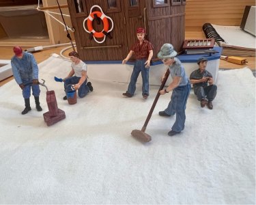
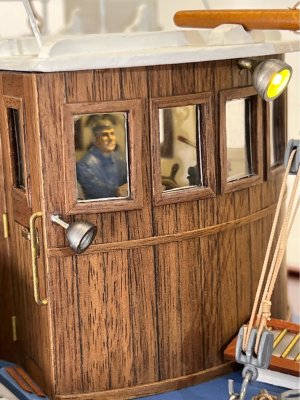
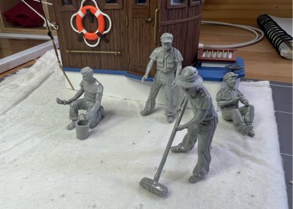
Here is the crew just after I had put them together (a few months ago). The arms, legs, heads, torso, legs, hats and accessories are all separate, so you have some flexibility in how you put them together. The skipper is already finished and was locked in the wheelhouse when that was closed up, so I’ll add a few crew mates to help out on deck. They won’t all make the cut…

1748149761520.jpeg

And here they are painted up…Vallejo acrylics, brush painted and washed and then sprayed with clear matte.

1748149777647.jpeg

The guy filling the jerry cans won’t make it aboard, but he was in one of the two kits that I had, so I made him up anyway. But I’ll use the jerry cans for an on-deck feature, strapped to the back of the wheelhouse. It’s also a non-smoking boat, so the guy sitting down on the right with a cigarette will get a nice cup of coffee to sate his craving. I ended up with three crew plus the skipper, I think that’s probably one more than they would have had when working, but she’s on her maiden voyage and they’re still getting a few jobs finished off. Here are a couple of them already recruited and hard at work…
1748149967412.jpeg

As Roy pointed out in an earlier post, they are dressed for warm weather and that’s because if you look closely at the scale map on the skipper’s table in the wheelhouse, you will see that they are fishing off the NSW Hunter coast (a long way from her home port of Esbjerg, Denmark), and even in winter it can get warm on a sunny day here.
 
Radio antenna
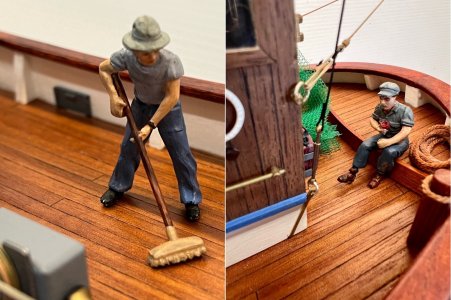
The issue with this is the same as for some other components…it will make it tricky to remove the wheelhouse as the rear mast comes out with the wheelhouse. So, I am going to string up a couple of temporary lines for the photos, but they will be removed in the longer term. I’m using some very fine enamelled copper wire that my old dad had in his shed…0.20mm diameter (scales to 6.6mm, so probably not too far off what would have been used). It comes off an old spool, hence coiled & wavy, so I gripped a length in the bench vice and gave it a gentle pull to just deform the wire a little and leave it straight enough to install. The Admiral is into jewellery making, so she donated a few tiny glass beads to use as insulators. I didn’t do the complete wiring as seen on the box photos, just enough to give an idea of there being a radio. Not a great photo, but you get the idea. The wire has just been wrapped around the antenna arms, no glue.
1748150299930.jpeg
 
The fish
What’s a trawler without fish…just another boat, right? The kit doesn’t come with anything pre-moulded to do this, and I was inspired by the photos of elCapi’s build (back in post #13). I tried my hand at carving a fish, it came out okay, but it just seemed too big for the 1:33 scale. So, I thought about 3D printing…I happened to have done a course at our local library’s ‘Fab Lab’ last year where they taught us how to use the modelling and slicing software and then they allow you to use their printers at a very reasonable hourly rate. I’m okay at modelling geometric shapes but organic shapes are beyond my skills, so I had a look around online and found a ‘pack’ of different fish (a folder of 20 STL files for $3) that would suit the wooden trays I’ve built, if they are printed at the right size. I used silver-grey filament and then gave them a light wash of blue and green colour (I toned it down a little further after these photos were taken).

Here’s a side-by-side with the fish as they come off the printer with their supports and flash still on, and one with them finished and glued into the trays (a little too colourful in this photo). Each fish is quite small and would probably better suit resin printing due to the fine detail, but I don’t think it really matters in this case when seen from normal model viewing distances. And the cost?, well, it’s $8 to use the Fab Lab for a session and I used 19 cents worth of filament in total!

1748150508373.png


The Last Job
She’s all fitted up and looking like a boat that wants to hit the high seas.

But the cradle needed something to give it a bit of weight, so I used a piece of Tasmanian oak I had left over from another job…with a routed edge and some stain it came up quite nicely. I sized it to be a bit smaller than the keel length, I think it then emphasises the boat rather than the stand. The cradle is screwed on from below.

One last small change I’ve made…I didn’t like the name plate supplied with the kit when it was installed on the wheelhouse front wall, there’s something about it that just didn’t look right (and I can’t put my finger on what). So, I decided to mount it on a piece of thin brass sheet and then made up a small, curved plinth to mount it on the new base plate. It looks much better there.

1748150596741.jpeg

Time for a few photos…
 
Final Photos
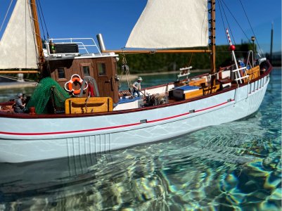
Well, we finally made it. Here are a few final shots of Mary Ann (here is a link to the ‘Completed Model Gallery’ post). I think the Billing kit (no. 472) has been a good place to start scale boat building. It’s rated as Advanced Beginner, and I think that is pretty fair. As someone who had worked with models (balsa aircraft) many years ago but had not done anything with a boat, it was a good compromise between introducing many often-used build skills, but in a model that is not too complex.

I have tried to build her to a level that I am satisfied with, and that has given me a good range of challenges and things to investigate and solve on the way. Add to that the custom changes relating to converting it to an RC build and it makes a good project. Just remember though, if you’re a complete novice, this kit does not provide any step-by-step instructions, so you are expected to work out how to put things together from some quite basic drawn images…hopefully this log will help.

A big thanks to those of you who have followed along, its great encouragement knowing that others are interested and think it’s worth investing some of their own time in giving it a read.

Here are a couple of final photos…

1748150690079.jpeg

1748150707532.jpeg

1748150718378.jpeg

1748150729751.jpeg

1748150750946.jpeg

1748150764292.jpeg

1748150776024.jpeg

1748150787053.jpeg

I’ll try and get a video of her on the water in the next few weeks and post a YouTube link later.
 
Last edited:
About the build log
I’ve enjoyed putting the log together, almost as much as the build itself, it gives you a good chance to reflect on your build and what you’ve learnt. For others thinking about how to do a log…I decided at the beginning that I would write it up in MS Word…I’m familiar with it, it allows me to do things at my own pace, and I can do it off-line. Also, it means I have a saved copy of everything if something should happen to the website. When I have a post that looks ready to put up on the site, I simply cut and paste it into the browser, it works very well, although I find that you need to do the text and photos separately. The only thing to watch out for is that Word does have a limit to the size of the file it can grow to…it can get big if you have many high-resolution photos. The solution is to save the log in Word as multiple ‘parts’ (two parts in the case of this log).

I usually write the Word version of the log around the same time as I’m doing that section of the build, so everything is fresh in my mind, and I remember what did and didn’t work. Sometimes I’ll be building a few sections concurrently, but the log has been organised into roughly sequential sections, so it doesn’t get confusing. The Word version (and the actual build) was usually a few weeks ahead of the website postings, so that I can space the posts at a reasonable rate.

I use my iPhone for the photos, it’s a few years old but still takes good photos if I keep my greasy fingers off the lens. I try to get the photos to tell the story by making sure that I have good lighting, include the tools or materials that I’m using at the time, and sometimes add something like a rule for scale. I don’t have any special lights for this…sometimes I just use the light from the bench magnifier or a torch, on the subject area…else it is bench lighting or the sun. I also try to take the photo without too much other stuff cluttering the background.

I encourage anyone to give it a go. I started it mainly because I couldn’t find any other detailed build logs for Mary Ann and I thought it might help another beginner…but I’d probably do it again in future just because I found that I enjoy doing it, and I hope it has also been interesting for those of you who have followed along.
 
Back
Top