Hi Grant, Thanks for your kind words.Good afternoon Pete. I missed your build so played a little catch up. A beautifully crafted model thus far. Cheers Grant
-

Win a Free Custom Engraved Brass Coin!!!
As a way to introduce our brass coins to the community, we will raffle off a free coin during the month of August. Follow link ABOVE for instructions for entering.
-

PRE-ORDER SHIPS IN SCALE TODAY!
The beloved Ships in Scale Magazine is back and charting a new course for 2026!
Discover new skills, new techniques, and new inspirations in every issue.
NOTE THAT OUR FIRST ISSUE WILL BE JAN/FEB 2026
You are using an out of date browser. It may not display this or other websites correctly.
You should upgrade or use an alternative browser.
You should upgrade or use an alternative browser.
Mary Ann by Billing Boats 472 - COMPLETED
- Thread starter pete_5
- Start date
- Watchers 20
-
- Tags
- billing boats mary ann
The finished hull
That certainly took longer than I expected. If you’d asked at the beginning of this project ‘what do you expect will be the most difficult step’, I would have said the outer hull planking (and it was) but I would have expected the painting and finishing of that to be pretty straightforward…but I came across a few challenges in the finishing process - like fibreglassing, using spray putty, multi-colour finish, clear finishes and pin striping. Lots of new skills there to develop. I think I’ll be investing in some airbrush equipment for the next model…rattled cans do work, but they are a bit inflexible.
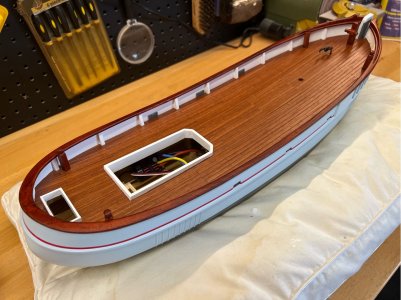
Here is a photo of the finished hull, ready for fitting out.
Next step is the electrical fit-out for the RC gear and lighting and then all the deck fixtures can be put in place.
That certainly took longer than I expected. If you’d asked at the beginning of this project ‘what do you expect will be the most difficult step’, I would have said the outer hull planking (and it was) but I would have expected the painting and finishing of that to be pretty straightforward…but I came across a few challenges in the finishing process - like fibreglassing, using spray putty, multi-colour finish, clear finishes and pin striping. Lots of new skills there to develop. I think I’ll be investing in some airbrush equipment for the next model…rattled cans do work, but they are a bit inflexible.
Here is a photo of the finished hull, ready for fitting out.

Next step is the electrical fit-out for the RC gear and lighting and then all the deck fixtures can be put in place.
Electrical Circuit
Before adding all of the build above the deck, I think it would be a good idea to get the internal wiring and other electrical components sorted out first. The access ports are relatively small and I’ll need all of the clearance that I can get to manoeuvre everything into place. My basic plan is to make the installation ‘removeable’…I have frustrated myself in other projects where I have built-in everything and then when something inevitably goes wrong it is a major job to get wiring and components out to fix things. So, I have used a few methods of attachment to help with this…the motor and servo are bolted with stainless machine screws and wood screws, the ESC is zip tied, the battery just uses rubber bands and all wiring either has plugs to an individual component or is part of the main wiring loom which can also be removed.
The electrical side of this project is relatively simple and doesn’t have any unusual characteristics, but I'll describe it in detail as I know that I would have found. it useful when I was starting this project.
The photo below is of the main wiring loom, it looks a bit messy while outside of the hull, but you won’t be able to see it when it is installed. The switches will be mounted in aluminium brackets attached to the underside of the deck, and the wiring for the fuse will fit neatly within the space inside the forward hold. The long lower lead runs back to the ESC. The smaller black upper leads from the voltage regulator will run forward and aft to the two lighting circuits. The radio receiver is not shown here because I will wait until the wiring is in place to work out the best positioning it and the antenna.

The switches were originally going to go under the wheelhouse, but I found that I could mount a couple of brackets under the forward main deck that allows good access via the forward hatch. This will simplify using the switches as I won’t have to remove the wheelhouse, and it may also free me up to make some changes to how I was thinking about the rigging where the main boom attaches to the wheelhouse. If I don’t have to lift the wheelhouse every time I use the boat, then I don’t mind if it is a little more difficult to remove it for those few times that I do have to. We will see.
The switches are mounted on custom aluminium brackets made up from pieces of angle section from a hardware store.

The lower surface of the bracket in the photo above, was drilled through about 4 times to allow the epoxy glue to ooze through and provide greater grip as it was glued to the underside of the deck. The two arms of the bracket can be seen coming down from the deck in the photo below (taken before the deck was sealed). The switch body slides up in between the arms and holds it securely. The other switch is mounted underneath the other side of the access port.

Both switches will be orientated such that they are rocked forward to turn on and rearward to turn off…less confusion for me. Here it is with all wiring in place.
And looking aft to the motor and ESC…
It’s reasonably neat, and I’m still able to remove any major item (or the whole lot) without it being a big deal. The extra weight also gives the hull a nice 'heft'. Next time we will have a look at the lighting circuit and radio receiver in more detail.
Before adding all of the build above the deck, I think it would be a good idea to get the internal wiring and other electrical components sorted out first. The access ports are relatively small and I’ll need all of the clearance that I can get to manoeuvre everything into place. My basic plan is to make the installation ‘removeable’…I have frustrated myself in other projects where I have built-in everything and then when something inevitably goes wrong it is a major job to get wiring and components out to fix things. So, I have used a few methods of attachment to help with this…the motor and servo are bolted with stainless machine screws and wood screws, the ESC is zip tied, the battery just uses rubber bands and all wiring either has plugs to an individual component or is part of the main wiring loom which can also be removed.
The electrical side of this project is relatively simple and doesn’t have any unusual characteristics, but I'll describe it in detail as I know that I would have found. it useful when I was starting this project.
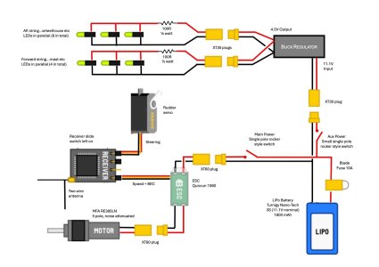
- BATTERY: I’m using a single 3S LiPo (11.1V) as the source for power, it has a rated capacity of 1800 mAh. I looked at several options for the battery, with the main criteria being that it had to fit within the dimensions of the bay I have built for it. I considered both 2S and 3S options but went with the 3S because it has a higher energy density for the package size and although I think I will only need 7.2V for motor (it is rated 6-12V) for scale speed, it will be good insurance to have the higher voltage available if needed. The motor and other equipment are all low consumption, so I am comfortable with the relatively low overall capacity of the battery.
- MOTOR: As mentioned much earlier in the log, the motor is a brushed MFA RE385LN (5 pole) noise attenuated motor with mount. It has a no-load max RPM of 7200 at 12V. At max efficiency it uses just under 1A, and the stall current is only 5A, so it is not going to put much load on the ESC or the cabling that I’m using.
- ESC: The ESC is a Hobbywing QuicRun 1060 60A 25A. This is capable of a much bigger motor than I’m running here, but it had better specs than other smaller units that I was looking at, and it has a good reputation for a reasonable cost. The unit was delivered with a Tamiya plug, but I have standardised on XT plugs so the Tamiya plug was cut off and XT60 soldered in place. This ESC has BEC for the radio receiver power.
- RECEIVER: The radio gear is Futaba (T6K transmitter with a R3006SB receiver). The receiver is 6 channel, again this is much more than I need here, but I already have it and buying a smaller (fewer channels) receiver doesn’t save you any money.
- SERVO: The rudder servo is a generic micro servo from PowerHD (model HD-1250MG). It is quite small but reasonably powerful for its size.
- REGULATOR: The lighting circuit uses a separate low-cost buck/boost regulator module…this is described in a future post.
- OTHER: All wiring is insulated multi-strand tinned wire…heavy gauge (mainly 16 AWG, it has a claimed rating of 15A continuous in an automotive environment) for the power circuit and a lighter guage for the auxiliary lighting circuit. All power connections use XT60 plugs, and the lighting circuit uses the smaller XT30 plugs. The plugs are all orientated such that the female plug (the side where the contacts are completely covered and you can't put something between the contacts) is on the battery end of any connection to reduce accidental shorts when the plugs are left unplugged. The wiring run that is closest to the battery has an inline fuse holder with a 10A mini blade style fuse (I’ll be testing a smaller fuse when everything is finished). There are switches for main power (on the battery positive rail only) and a separate one for the lighting circuit. I decided to wire the auxiliary circuit’s switch independent of the main power switch (but still downstream of the fuse), so that I can turn the lights on for display without also powering the ESC/Receiver etc. The battery also has a 3-channel balance charging plug, with 20cm extension cable, that is not shown in the diagram below.

The photo below is of the main wiring loom, it looks a bit messy while outside of the hull, but you won’t be able to see it when it is installed. The switches will be mounted in aluminium brackets attached to the underside of the deck, and the wiring for the fuse will fit neatly within the space inside the forward hold. The long lower lead runs back to the ESC. The smaller black upper leads from the voltage regulator will run forward and aft to the two lighting circuits. The radio receiver is not shown here because I will wait until the wiring is in place to work out the best positioning it and the antenna.

The switches were originally going to go under the wheelhouse, but I found that I could mount a couple of brackets under the forward main deck that allows good access via the forward hatch. This will simplify using the switches as I won’t have to remove the wheelhouse, and it may also free me up to make some changes to how I was thinking about the rigging where the main boom attaches to the wheelhouse. If I don’t have to lift the wheelhouse every time I use the boat, then I don’t mind if it is a little more difficult to remove it for those few times that I do have to. We will see.
The switches are mounted on custom aluminium brackets made up from pieces of angle section from a hardware store.

The lower surface of the bracket in the photo above, was drilled through about 4 times to allow the epoxy glue to ooze through and provide greater grip as it was glued to the underside of the deck. The two arms of the bracket can be seen coming down from the deck in the photo below (taken before the deck was sealed). The switch body slides up in between the arms and holds it securely. The other switch is mounted underneath the other side of the access port.

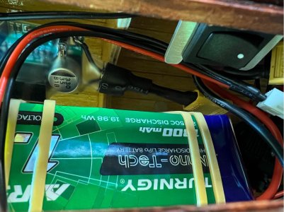
Both switches will be orientated such that they are rocked forward to turn on and rearward to turn off…less confusion for me. Here it is with all wiring in place.

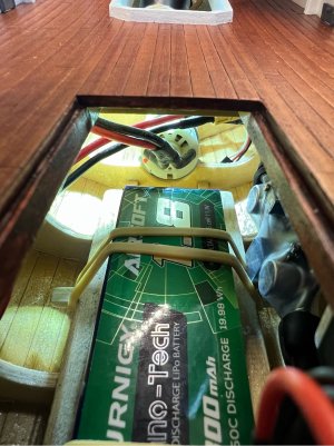
And looking aft to the motor and ESC…

It’s reasonably neat, and I’m still able to remove any major item (or the whole lot) without it being a big deal. The extra weight also gives the hull a nice 'heft'. Next time we will have a look at the lighting circuit and radio receiver in more detail.
Lighting Power Supply
The LED lighting was described in detail in early posts (from #35 onward). The lights will be running from a single switch mode buck/boost regulator, you can pick them up on eBay for a few dollars each. It has a simple screw pot on the module’s board to set the desired output voltage and that’s about it. They have a reasonably high conversion efficiency, so they do not generate much heat when running at low currents. In my case, the input voltage is nominally 11.1V, and I had sized the lighting circuit to run on a 4.5V voltage. The LEDs (about 10 in total) run at 12ma each, so the total output current will be around 120ma at 4.5V…just over 1/2 watt…not a big load for the regulator module, rated for 2 to 3 amps, so it will handle that without needing any heatsinking.
The regulator shouldn’t need any regular attention, but it will be placed somewhere that I can get to it if needed. The module is only 48 x 26mm, so it has a small footprint. There is a reasonable amount of space in the forward area of the hull, near the forward hatch, on the wall beside the battery, so that is where it will go. This also keeps it away from the busy and potentially warmer area under the wheelhouse. The regulator output will link to the forward light circuit and another to the wheelhouse circuit, they are all wired to the same switch so they will all be on or off, to keep it simple. The module has been covered in a heat-shrink plastic sleeve to provide splash protection. All other soldered leads are finished with double walled heat-shrink (it has an internal glue coating) to minimise corrosion.
For reference, this is the voltage regulator used here...

You can see it installed on the port side next to the battery in the last two photos of the previous post. I’ve run a test with the wheelhouse lights and it all works as expected. The lighting circuit has been wired independently to the power for the RC setup, partly because I don’t have an ‘RC switch’ (a component like a servo, but it’s a switch, to allow an RC channel to do the switching) but also because it simplifies turning them on if I just want to demo or display the model with the lights on. There is a schematic of the wiring diagram in a post above.
The LED lighting was described in detail in early posts (from #35 onward). The lights will be running from a single switch mode buck/boost regulator, you can pick them up on eBay for a few dollars each. It has a simple screw pot on the module’s board to set the desired output voltage and that’s about it. They have a reasonably high conversion efficiency, so they do not generate much heat when running at low currents. In my case, the input voltage is nominally 11.1V, and I had sized the lighting circuit to run on a 4.5V voltage. The LEDs (about 10 in total) run at 12ma each, so the total output current will be around 120ma at 4.5V…just over 1/2 watt…not a big load for the regulator module, rated for 2 to 3 amps, so it will handle that without needing any heatsinking.
The regulator shouldn’t need any regular attention, but it will be placed somewhere that I can get to it if needed. The module is only 48 x 26mm, so it has a small footprint. There is a reasonable amount of space in the forward area of the hull, near the forward hatch, on the wall beside the battery, so that is where it will go. This also keeps it away from the busy and potentially warmer area under the wheelhouse. The regulator output will link to the forward light circuit and another to the wheelhouse circuit, they are all wired to the same switch so they will all be on or off, to keep it simple. The module has been covered in a heat-shrink plastic sleeve to provide splash protection. All other soldered leads are finished with double walled heat-shrink (it has an internal glue coating) to minimise corrosion.
For reference, this is the voltage regulator used here...

You can see it installed on the port side next to the battery in the last two photos of the previous post. I’ve run a test with the wheelhouse lights and it all works as expected. The lighting circuit has been wired independently to the power for the RC setup, partly because I don’t have an ‘RC switch’ (a component like a servo, but it’s a switch, to allow an RC channel to do the switching) but also because it simplifies turning them on if I just want to demo or display the model with the lights on. There is a schematic of the wiring diagram in a post above.
RC Radio Receiver
Santa was very kind to me last Christmas. He left a big box under the tree with a Futaba T6K and receiver in it. Although it’s not a particularly expensive radio, it’s certainly more than I need for this project. I selected it mainly because it has multiple memories, and I didn’t want to have to deal with a bunch of different transmitters as I build more models…or when I try my hand at flying. And the Futaba brand, because it’s been there longer than I have, so they must be doing something right.
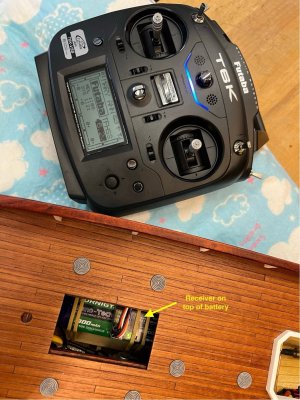
The receiver is quite small and light. I had considered installing this under the wheelhouse on a false floor, but that will put it over the motor and next to the ESC, so I think it will be a lot quieter (RF-wise) if I move it further forward to the forward hatch. As it turns out, the ideal spot is under the elastic bands of the battery...they hold it down and give good access to the receiver when needed.
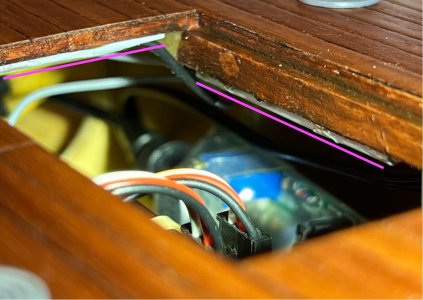
The instructions suggest laying out the two-armed antenna in a right-angle pattern for improved reception, so these have been attached under the main deck using hollow plastic tubing. The short lengths of plastic tubing were glued under the supports of the hatch cover, on the cross and longitudinal members, so that the antenna wires could be slid into the fine tubes and held at the ideal 90 degrees without the wires themselves needing to be glued in place.
In this photo, the fine white tubing can be seen above the two pink lines. You can also see the black antenna wire going in one end of one of them…
The ESC has a battery elimination circuit (BEC), so I don’t need a separate connection for power, but I did need to extend the signal wires with 20cm extension leads. This makes the wiring runs simple to route and keep out of the way as they make their way back to the ESC and the rudder servo.
The transmitter is set up as Mode 2 and doesn’t have a dedicated ‘boat’ profile, so I am using the ‘airplane’ profile and ‘1AIL’ wing type. That gives me throttle on channel 1 (up/down on the spring-loaded left stick) and aileron (boat rudder in this case) on channel 3 (left/right on the unsprung right stick). I made a few other small modifications to the parameters…the throttle channel can be set to exponential or the standard dual rate using one of the switches on the transmitter, and set the end-points for the rudder channel to the max 140% as I have up to +/- 90 deg swing available - that will be tested and refined when the rudder is re-installed (planned to be the last job). The throttle is set to ‘reverse’ direction by default in the selected profile, so that didn’t need to be changed to suit this application.
Here it is installed…
I’ve confirmed that everything works as expected, so that’s it for the internal electricals. Next, we will move onto the deck fit-out…the home stretch.
Santa was very kind to me last Christmas. He left a big box under the tree with a Futaba T6K and receiver in it. Although it’s not a particularly expensive radio, it’s certainly more than I need for this project. I selected it mainly because it has multiple memories, and I didn’t want to have to deal with a bunch of different transmitters as I build more models…or when I try my hand at flying. And the Futaba brand, because it’s been there longer than I have, so they must be doing something right.
The receiver is quite small and light. I had considered installing this under the wheelhouse on a false floor, but that will put it over the motor and next to the ESC, so I think it will be a lot quieter (RF-wise) if I move it further forward to the forward hatch. As it turns out, the ideal spot is under the elastic bands of the battery...they hold it down and give good access to the receiver when needed.
The instructions suggest laying out the two-armed antenna in a right-angle pattern for improved reception, so these have been attached under the main deck using hollow plastic tubing. The short lengths of plastic tubing were glued under the supports of the hatch cover, on the cross and longitudinal members, so that the antenna wires could be slid into the fine tubes and held at the ideal 90 degrees without the wires themselves needing to be glued in place.
In this photo, the fine white tubing can be seen above the two pink lines. You can also see the black antenna wire going in one end of one of them…

The ESC has a battery elimination circuit (BEC), so I don’t need a separate connection for power, but I did need to extend the signal wires with 20cm extension leads. This makes the wiring runs simple to route and keep out of the way as they make their way back to the ESC and the rudder servo.
The transmitter is set up as Mode 2 and doesn’t have a dedicated ‘boat’ profile, so I am using the ‘airplane’ profile and ‘1AIL’ wing type. That gives me throttle on channel 1 (up/down on the spring-loaded left stick) and aileron (boat rudder in this case) on channel 3 (left/right on the unsprung right stick). I made a few other small modifications to the parameters…the throttle channel can be set to exponential or the standard dual rate using one of the switches on the transmitter, and set the end-points for the rudder channel to the max 140% as I have up to +/- 90 deg swing available - that will be tested and refined when the rudder is re-installed (planned to be the last job). The throttle is set to ‘reverse’ direction by default in the selected profile, so that didn’t need to be changed to suit this application.
Here it is installed…

I’ve confirmed that everything works as expected, so that’s it for the internal electricals. Next, we will move onto the deck fit-out…the home stretch.
The final fit-out
I’ll start with something very simple, as you can see them in the photos of the last post. The deck hold covers (not sure if that’s technically the right name). They are supplied with the kit and are simple moulded plastic components. They look very plasticky as delivered, the colour is too light, and they needed a bit of aging. The instructions say they are to be grey, and all photos of completed models seem to be. So, I cleaned them up by removing some flashing and sanded the bottoms to get a rough surface for gluing later. The first step was to put a black wash of very watery acrylic on them and leave it sitting in the rings to dry, then I dry-brushed some darker grey paint across tops to leave a mottled effect. I suspect that on the real boats these would have been either brass or maybe cast iron, in which case they would have been a different colour altogether. The covers were epoxy glued to the deck, as you can see above.
Finalising the wheelhouse
Well, a few things must change from the kit's static design to allow for the RC side of this model, an important one being that the wheelhouse needs to be remove-able so that I can get access to the drivetrain and steering gear beneath. This adds a small complication as the following issues need to be resolved…
My solutions to most of the issues are then fairly simple…
The build of the wheelhouse and mast was described much earlier in the log, so I am just focusing on what needs to be different from the Billing plan to suit this application.
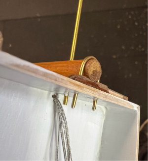
The plans call for the aft mast to be attached to the main deck and to the top of the rear of the wheelhouse. I’ve just duplicated the upper attachment (a brass wire u-bolt, shown in the yellow circle) at the lower section of the structure, and also added a brass wire rod (the end can be seen at the blue arrow) straight through the mast and back wall to stop the mast from any unwanted rotation or vertical movement within the U-bolts. Each of the U-bolts pulls the mast against a wooden saddle block to keep the mast centred and also holds it away from the back of the structure.

Here it is from inside (below)…the wire rod ends haven’t been trimmed in this shot. The wires were glued as they were installed to prevent pull-out. The fine silver wires in this picture are for the wheelhouse lights, there is a conduit tube running up the inside of the cabin (more on that later).
The Wheelhouse Rigging
The rigging is pretty simple. The thread provided by the kit for the ropes doesn’t seem to be of high quality, but I don’t have anything else at hand (it’s such a small amount, it can always be re-done if I find something better later...I think I order some scale rope). In the photo on the box, the shrouds are a black (tarred) rope (not provided in the kit) and I like that look, so I found some old black waxed linen thread in our sewing kit and pressed that into service. I followed the vague instructions for the other sheets. I’m not super happy with it, but it will be okay for the moment.
That does it for the aft mast.
I’ll start with something very simple, as you can see them in the photos of the last post. The deck hold covers (not sure if that’s technically the right name). They are supplied with the kit and are simple moulded plastic components. They look very plasticky as delivered, the colour is too light, and they needed a bit of aging. The instructions say they are to be grey, and all photos of completed models seem to be. So, I cleaned them up by removing some flashing and sanded the bottoms to get a rough surface for gluing later. The first step was to put a black wash of very watery acrylic on them and leave it sitting in the rings to dry, then I dry-brushed some darker grey paint across tops to leave a mottled effect. I suspect that on the real boats these would have been either brass or maybe cast iron, in which case they would have been a different colour altogether. The covers were epoxy glued to the deck, as you can see above.
Finalising the wheelhouse
Well, a few things must change from the kit's static design to allow for the RC side of this model, an important one being that the wheelhouse needs to be remove-able so that I can get access to the drivetrain and steering gear beneath. This adds a small complication as the following issues need to be resolved…
- The aft mast and its rigging are designed to be attached to both the deck and wheelhouse, locking everything together
- A fixed radio antenna wire runs atop between the main and aft masts
- The rigging of the main mast boom is connected to the raised foredeck of the wheelhouse
- The main mast boom rests on the roof of the wheelhouse
- The fishing rig (gallows & otter boards) mounted on the aft starboard bulwark have metal rods that connect to the wheelhouse roof.
My solutions to most of the issues are then fairly simple…
- Attach the aft mast directly to the wheelhouse only (solves 1 above)
- The mast-based antenna wires are a nice-to-have, but will be deleted (sort of solves 2 above)…I may reconsider this is the longer term if I rarely remove the wheelhouse.
- I was going to add some short posts directly to the deck in front of the raised deck of wheelhouse (similar to the bitts already in place), to secure the main boom rigging. But now I’ll leave this are shown in the drawings and make the final connection of the rigging into a ‘hook’, so that they can be disconnected. (solves 3 above)
- I’ll leave the main boom support on the roof of the wheelhouse, but it will just be resting there and will be swung aside when removing the wheelhouse (item 4 above)
- The fishing rig will be installed as designed, but the rod ends will not be glued in place on the wheelhouse (ie, that’s still a work-in-progress, I’ll see what makes sense)
The build of the wheelhouse and mast was described much earlier in the log, so I am just focusing on what needs to be different from the Billing plan to suit this application.
The plans call for the aft mast to be attached to the main deck and to the top of the rear of the wheelhouse. I’ve just duplicated the upper attachment (a brass wire u-bolt, shown in the yellow circle) at the lower section of the structure, and also added a brass wire rod (the end can be seen at the blue arrow) straight through the mast and back wall to stop the mast from any unwanted rotation or vertical movement within the U-bolts. Each of the U-bolts pulls the mast against a wooden saddle block to keep the mast centred and also holds it away from the back of the structure.

Here it is from inside (below)…the wire rod ends haven’t been trimmed in this shot. The wires were glued as they were installed to prevent pull-out. The fine silver wires in this picture are for the wheelhouse lights, there is a conduit tube running up the inside of the cabin (more on that later).

The Wheelhouse Rigging
The rigging is pretty simple. The thread provided by the kit for the ropes doesn’t seem to be of high quality, but I don’t have anything else at hand (it’s such a small amount, it can always be re-done if I find something better later...I think I order some scale rope). In the photo on the box, the shrouds are a black (tarred) rope (not provided in the kit) and I like that look, so I found some old black waxed linen thread in our sewing kit and pressed that into service. I followed the vague instructions for the other sheets. I’m not super happy with it, but it will be okay for the moment.
That does it for the aft mast.
Wheelhouse roof attachment and caulking
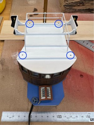
Some of you may remember that way back when I was building the wheelhouse (about 12 months ago!) I didn’t permanently attach the roof, as I was still finalising wiring etc. So now that the aft mast is attached and its wiring complete, I can add the roof. I always wanted it to be removeable, in case I need to fix something (lighting etc), so I previously added some internal roof beams that were made from a dense enough timber that I could put some small diameter screws into them. I had already bought some M1 x 10mm stainless steel screws for the rudder mounts and have plenty of these left over, so I used four of them to attach the roof. They have enough purchase on the underlying beams that I can pull down the slight curve of the front wall and get a good fit.
Here is where they are placed the screws (blue circles in photo below)…the rear screws go down through the beam on top of the roof, and the ones toward the front are straight through the ply roof. I used the small Philips head screwdriver to make a small countersinking shape in the timber before screwing them down and they sit flush. They have since been covered with very small, white-painted wood veneer strips to hide the cross-heads.
One small issue I found was that when the internal lights were on, they were leaking a little visible light over the tops of the side walls. I didn’t want to add filler or sealant as that would be broken next time I remove the roof, so I thought about adding a soft gasket…I was thinking of using a strand of wool, but didn’t have any, so I used the black thread mentioned above. It was tacked down at the ends, with a tiny amount of CA. When the roof is reattached, it compresses it a little and stops the light shining through.
Here is the thread running along the top of the wall before screwing the roof closed.

So, the wheelhouse is now closed up, there is a bit of tidying of the wiring underneath the floor...we'll take a look at that next time.
Some of you may remember that way back when I was building the wheelhouse (about 12 months ago!) I didn’t permanently attach the roof, as I was still finalising wiring etc. So now that the aft mast is attached and its wiring complete, I can add the roof. I always wanted it to be removeable, in case I need to fix something (lighting etc), so I previously added some internal roof beams that were made from a dense enough timber that I could put some small diameter screws into them. I had already bought some M1 x 10mm stainless steel screws for the rudder mounts and have plenty of these left over, so I used four of them to attach the roof. They have enough purchase on the underlying beams that I can pull down the slight curve of the front wall and get a good fit.
Here is where they are placed the screws (blue circles in photo below)…the rear screws go down through the beam on top of the roof, and the ones toward the front are straight through the ply roof. I used the small Philips head screwdriver to make a small countersinking shape in the timber before screwing them down and they sit flush. They have since been covered with very small, white-painted wood veneer strips to hide the cross-heads.

One small issue I found was that when the internal lights were on, they were leaking a little visible light over the tops of the side walls. I didn’t want to add filler or sealant as that would be broken next time I remove the roof, so I thought about adding a soft gasket…I was thinking of using a strand of wool, but didn’t have any, so I used the black thread mentioned above. It was tacked down at the ends, with a tiny amount of CA. When the roof is reattached, it compresses it a little and stops the light shining through.
Here is the thread running along the top of the wall before screwing the roof closed.

So, the wheelhouse is now closed up, there is a bit of tidying of the wiring underneath the floor...we'll take a look at that next time.
Final wiring of the rear lighting circuit
The lighting on the boat is split into two main circuits…fore and aft. So, I have wiring coming up through the wheelhouse for the lights on the rear of the aft mast, two internal cabin lights, the forward flood light, and the two nav lights on the top-sides of the cabin. The wiring is all hidden and it is very fine and therefore easily broken. I’m bringing the power up from the regulator in a single feed to the bottom of the wheelhouse and then splitting it out to the individual lights. This single feed will have a small XT30 connector back into the hull so that the whole structure can be removed easily. This is then terminated at a small screw terminal block and each set of lights gets a feed coming of there to each set of individual wires. I find it is much easier to deal with the wiring if you reduce the number down in a few steps, rather than trying to terminate all of the fine wires in the one spot. Even so, it looks like a dog’s breakfast under the cabin floor, and I know that they will get ‘snagged’ by something at some point…

So, I decided to add a false floor to cover and protect the wires but still allow removal. In the image on the left I added some pads, then cut a floor from a sheet of 1.5mm paulownia (like balsa but stiffer), added a cut out for the incoming power feed, and painted it for protection. It was screwed in using more of those very small stainless screws.
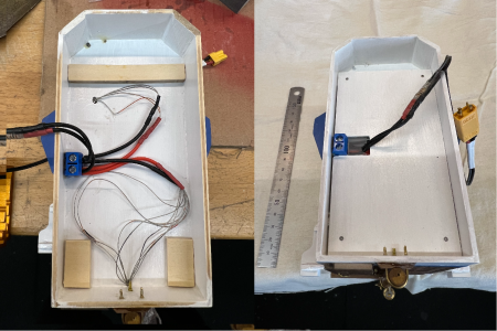
To help with cable relief, I added a small sheet of plastic over the wires but compressed under the new cover. If the wire gets tugged too hard, this will ‘give’ a little before breaking anything. The plastic sheet is not glued in, it’s just held under the pressure of the cover. Oh, and those ends of the brass wire that you see sticking through at the bottom of the photos above have been trimmed off (after I wondered why I couldn’t get the wheelhouse to fit over its deck coaming!)

 , the wheelhouse/aft mast structure is almost complete and ready for installation. There are still a few things to be sorted from my list further above, but they with show up as I address them in future posts.
The lighting on the boat is split into two main circuits…fore and aft. So, I have wiring coming up through the wheelhouse for the lights on the rear of the aft mast, two internal cabin lights, the forward flood light, and the two nav lights on the top-sides of the cabin. The wiring is all hidden and it is very fine and therefore easily broken. I’m bringing the power up from the regulator in a single feed to the bottom of the wheelhouse and then splitting it out to the individual lights. This single feed will have a small XT30 connector back into the hull so that the whole structure can be removed easily. This is then terminated at a small screw terminal block and each set of lights gets a feed coming of there to each set of individual wires. I find it is much easier to deal with the wiring if you reduce the number down in a few steps, rather than trying to terminate all of the fine wires in the one spot. Even so, it looks like a dog’s breakfast under the cabin floor, and I know that they will get ‘snagged’ by something at some point…

So, I decided to add a false floor to cover and protect the wires but still allow removal. In the image on the left I added some pads, then cut a floor from a sheet of 1.5mm paulownia (like balsa but stiffer), added a cut out for the incoming power feed, and painted it for protection. It was screwed in using more of those very small stainless screws.

To help with cable relief, I added a small sheet of plastic over the wires but compressed under the new cover. If the wire gets tugged too hard, this will ‘give’ a little before breaking anything. The plastic sheet is not glued in, it’s just held under the pressure of the cover. Oh, and those ends of the brass wire that you see sticking through at the bottom of the photos above have been trimmed off (after I wondered why I couldn’t get the wheelhouse to fit over its deck coaming!)

 , the wheelhouse/aft mast structure is almost complete and ready for installation. There are still a few things to be sorted from my list further above, but they with show up as I address them in future posts.
Cordage - Kit supplied vs the Real Stuff
You may have noticed in the photos above that the rigging of the aft mast is missing. I had rigged it a few months ago using a combination of the ‘rope’ supplied with the kit, and some thick black linen thread I found in the admiral’s sewing kit. I wasn’t very impressed with the kit supplied product…it looked and felt like fine cotton twine rather than rope and was detracting from the work put into the model. So, I thought I might purchase some scale rope just to see what the difference is…chalk vs cheese as it turns out. I bought a few sizes and colours of polyester rope from Ropes of Scale and the product is beautiful.
Here is a comparison photo of the scale ropes (in the plastic bags) and kit supplied string (on the bobbins)…

I did a couple of ‘before and after’ pics of the rigging so I could contrast and compare the cost vs end result. It’s not a cheap product, but for the small amount of rope used on this model the cost is insignificant…and the result is way more realistic and feels to scale.
Here are a couple of side-by-side examples of before/after. Just the reduction in fuzzies is significant, but seeing the lay of the rope in the scale product makes a big difference in real life. The colour of the ‘tan’ range of ropes also looks much better than the kit version.
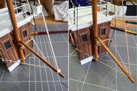
And another (before/after)…
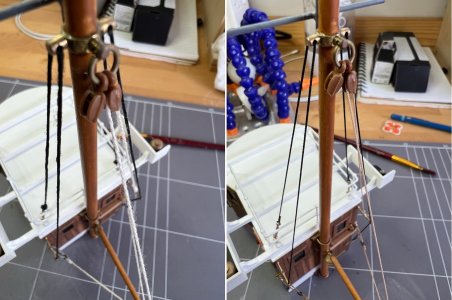
Well worth the couple of hours of rework. I also terminated the rope differently this time…the main 0.5mm rope is secured to itself with thin CA, then wrapped with finer 0.35mm rope to give a smaller, tighter looking termination. I also found that for some of the rope it helped to put a very fine dab of thin CA on the rope where I was planning to cut it, to prevent the tiny amount of unwinding that sometimes happens. All the CA applications were done using a 1ml syringe with its needle intact (you can get them from the local pharmacy) …I found that trying to do it directly from the Zap bottle, even with a thin plastic tip, I didn’t have the same control that the syringe plunger gives you.
That’s it for today, next I’ll get started on the sails.
You may have noticed in the photos above that the rigging of the aft mast is missing. I had rigged it a few months ago using a combination of the ‘rope’ supplied with the kit, and some thick black linen thread I found in the admiral’s sewing kit. I wasn’t very impressed with the kit supplied product…it looked and felt like fine cotton twine rather than rope and was detracting from the work put into the model. So, I thought I might purchase some scale rope just to see what the difference is…chalk vs cheese as it turns out. I bought a few sizes and colours of polyester rope from Ropes of Scale and the product is beautiful.
Here is a comparison photo of the scale ropes (in the plastic bags) and kit supplied string (on the bobbins)…

I did a couple of ‘before and after’ pics of the rigging so I could contrast and compare the cost vs end result. It’s not a cheap product, but for the small amount of rope used on this model the cost is insignificant…and the result is way more realistic and feels to scale.
Here are a couple of side-by-side examples of before/after. Just the reduction in fuzzies is significant, but seeing the lay of the rope in the scale product makes a big difference in real life. The colour of the ‘tan’ range of ropes also looks much better than the kit version.

And another (before/after)…

Well worth the couple of hours of rework. I also terminated the rope differently this time…the main 0.5mm rope is secured to itself with thin CA, then wrapped with finer 0.35mm rope to give a smaller, tighter looking termination. I also found that for some of the rope it helped to put a very fine dab of thin CA on the rope where I was planning to cut it, to prevent the tiny amount of unwinding that sometimes happens. All the CA applications were done using a 1ml syringe with its needle intact (you can get them from the local pharmacy) …I found that trying to do it directly from the Zap bottle, even with a thin plastic tip, I didn’t have the same control that the syringe plunger gives you.
That’s it for today, next I’ll get started on the sails.
Sails
I decided to get the sails sorted out before I install the masts on the boat…and I’m glad that I did, it makes it a lot easier and less likely to damage anything. The kit provides a small sheet of fabric, in a natural cotton colour, and a pattern for cutting and sewing the hem and faux sewing lines to indicate a panelled construction. There are no instructions, but I’m fortunate in that my elderly mum is a very handy seamstress and has all the machinery to do the job…not that I contracted the job to her, no, I got her to give me a lesson in use of the machine and had a go myself. As it turns out, it’s not too hard to get a reasonable finish on a relatively trivial task such as this. We used a thread of similar colour to the sail cloth, in hindsight we probably would have been better off to use something a little darker, but that will have to wait for my next model.
I copied the lines from the sail plan to the cloth using pencil, then ironed the seam back on itself ready for stitching. The panel lines were also marked in light dashed pencil lines (next time I think I would do a light un-dashed line…I think it would then fade into the background of the stitching). The stitching itself is pretty straightforward when you have a machine to do the work. A bit of knotting of loose ends and cleaning up threads hanging from the edge and we were done.
Here is a photo, with a bit of contrast lighting to show up the ‘panelling’, before it was attached to the mast.
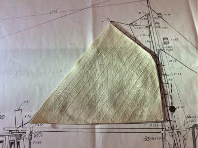
Attaching it to the various spars and mast is a little fiddly, but not too hard. I used 0.35mm, tan coloured rope for the loops around the top spar (gaff), one for each panel of the sail, they were tied off with a simple reef knot and thin CA spot glued to make sure nothing comes undone. For the mast, black plastic hoops are supplied with the kit, they don’t look too bad and have a moulded eye to accept a rope for tying off the sail. Again, there is a hoop for each panel (for the 6 panels that meet the mast). A similar process was used for these, except I used 0.5mm tan rope. I had a large sewing needle that made it easy to pierce the sail in the hemmed area and then tie it through the hoop’s eye and finish with a reef knot and CA.

The clew of the sail appears to be attached to the free end of the boom by chain. I imagine I’ll do that by tying the last link of chain to the corner of the sail. I won’t do that until the mast is stepped and the boom installed, otherwise you can bet it will be the wrong length.
A note on the plastic cleats
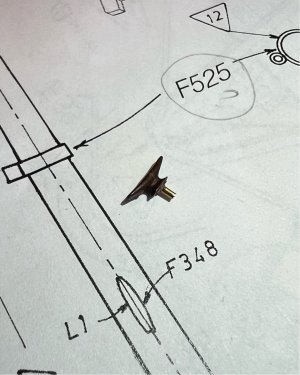
The kit supplies several very small brown plastic cleats for use on the masts. Just a warning on these…the short plastic stalk that is moulded on their base for attaching to the mast, seems to be a weak point in their design, I’ve had a few break off after installation just with normal handling. My solution was to drill them out and glue in a short length of 1mm brass wire…working well so far.
I decided to get the sails sorted out before I install the masts on the boat…and I’m glad that I did, it makes it a lot easier and less likely to damage anything. The kit provides a small sheet of fabric, in a natural cotton colour, and a pattern for cutting and sewing the hem and faux sewing lines to indicate a panelled construction. There are no instructions, but I’m fortunate in that my elderly mum is a very handy seamstress and has all the machinery to do the job…not that I contracted the job to her, no, I got her to give me a lesson in use of the machine and had a go myself. As it turns out, it’s not too hard to get a reasonable finish on a relatively trivial task such as this. We used a thread of similar colour to the sail cloth, in hindsight we probably would have been better off to use something a little darker, but that will have to wait for my next model.
I copied the lines from the sail plan to the cloth using pencil, then ironed the seam back on itself ready for stitching. The panel lines were also marked in light dashed pencil lines (next time I think I would do a light un-dashed line…I think it would then fade into the background of the stitching). The stitching itself is pretty straightforward when you have a machine to do the work. A bit of knotting of loose ends and cleaning up threads hanging from the edge and we were done.
Here is a photo, with a bit of contrast lighting to show up the ‘panelling’, before it was attached to the mast.

Attaching it to the various spars and mast is a little fiddly, but not too hard. I used 0.35mm, tan coloured rope for the loops around the top spar (gaff), one for each panel of the sail, they were tied off with a simple reef knot and thin CA spot glued to make sure nothing comes undone. For the mast, black plastic hoops are supplied with the kit, they don’t look too bad and have a moulded eye to accept a rope for tying off the sail. Again, there is a hoop for each panel (for the 6 panels that meet the mast). A similar process was used for these, except I used 0.5mm tan rope. I had a large sewing needle that made it easy to pierce the sail in the hemmed area and then tie it through the hoop’s eye and finish with a reef knot and CA.

The clew of the sail appears to be attached to the free end of the boom by chain. I imagine I’ll do that by tying the last link of chain to the corner of the sail. I won’t do that until the mast is stepped and the boom installed, otherwise you can bet it will be the wrong length.
A note on the plastic cleats
The kit supplies several very small brown plastic cleats for use on the masts. Just a warning on these…the short plastic stalk that is moulded on their base for attaching to the mast, seems to be a weak point in their design, I’ve had a few break off after installation just with normal handling. My solution was to drill them out and glue in a short length of 1mm brass wire…working well so far.

The forward access hatch & coaming
This is another area that is a modification to the original kit design, to allow for access to the RC battery and electrical connections. The battery that I ended up purchasing fits through the forward hatch…I was planning to insert it via the main access port under the wheelhouse and use this hatch to allow easy securing of the battery once it is installed, but now I have both options available. This hatch also gives me the ability to get into the forward area of the hull for lighting wiring and other components. I’m using the kit’s wooden fencing just aft of the main mast, to mask that there is a hatch under there and act as the coaming, and then the kit’s raised access hatchway as the means to grip the deck hatch and remove or install it
The fenced area is constructed almost as per the drawings, except that my dimensions are just slightly larger than the access port and I will be gluing it to deck planking and making sure that it is watertight as this will act as the coaming for this opening. It is not an ideal arrangement as the coaming should have a covering over it (to prevent rain and splashed water from being contained, but it will stop any water that is washing across the deck. In hindsight, I could have built it to a design that effectively added a false floor across the opening with a coaming, within the fenced area…but this boat is never going to see that sort of weather or rough seas.
Here is the opening…

This is the installed coaming, in the form of the kit’s low fenced area. It was epoxy glued to the deck to ensure a good water-tight seal around the perimeter…
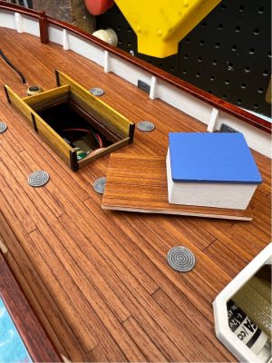
This is the kit’s raised hatchway, mounted on the section of deck that lifts away to open the access port...

That's it for today, next time I'll be preparing for the stepping of the mast.
This is another area that is a modification to the original kit design, to allow for access to the RC battery and electrical connections. The battery that I ended up purchasing fits through the forward hatch…I was planning to insert it via the main access port under the wheelhouse and use this hatch to allow easy securing of the battery once it is installed, but now I have both options available. This hatch also gives me the ability to get into the forward area of the hull for lighting wiring and other components. I’m using the kit’s wooden fencing just aft of the main mast, to mask that there is a hatch under there and act as the coaming, and then the kit’s raised access hatchway as the means to grip the deck hatch and remove or install it
The fenced area is constructed almost as per the drawings, except that my dimensions are just slightly larger than the access port and I will be gluing it to deck planking and making sure that it is watertight as this will act as the coaming for this opening. It is not an ideal arrangement as the coaming should have a covering over it (to prevent rain and splashed water from being contained, but it will stop any water that is washing across the deck. In hindsight, I could have built it to a design that effectively added a false floor across the opening with a coaming, within the fenced area…but this boat is never going to see that sort of weather or rough seas.
Here is the opening…

This is the installed coaming, in the form of the kit’s low fenced area. It was epoxy glued to the deck to ensure a good water-tight seal around the perimeter…

This is the kit’s raised hatchway, mounted on the section of deck that lifts away to open the access port...

That's it for today, next time I'll be preparing for the stepping of the mast.
Good afternoon.Cordage - Kit supplied vs the Real Stuff
You may have noticed in the photos above that the rigging of the aft mast is missing. I had rigged it a few months ago using a combination of the ‘rope’ supplied with the kit, and some thick black linen thread I found in the admiral’s sewing kit. I wasn’t very impressed with the kit supplied product…it looked and felt like fine cotton twine rather than rope and was detracting from the work put into the model. So, I thought I might purchase some scale rope just to see what the difference is…chalk vs cheese as it turns out. I bought a few sizes and colours of polyester rope from Ropes of Scale and the product is beautiful.
Here is a comparison photo of the scale ropes (in the plastic bags) and kit supplied string (on the bobbins)…
View attachment 509178
I did a couple of ‘before and after’ pics of the rigging so I could contrast and compare the cost vs end result. It’s not a cheap product, but for the small amount of rope used on this model the cost is insignificant…and the result is way more realistic and feels to scale.
Here are a couple of side-by-side examples of before/after. Just the reduction in fuzzies is significant, but seeing the lay of the rope in the scale product makes a big difference in real life. The colour of the ‘tan’ range of ropes also looks much better than the kit version.
View attachment 509179
And another (before/after)…
View attachment 509180
Well worth the couple of hours of rework. I also terminated the rope differently this time…the main 0.5mm rope is secured to itself with thin CA, then wrapped with finer 0.35mm rope to give a smaller, tighter looking termination. I also found that for some of the rope it helped to put a very fine dab of thin CA on the rope where I was planning to cut it, to prevent the tiny amount of unwinding that sometimes happens. All the CA applications were done using a 1ml syringe with its needle intact (you can get them from the local pharmacy) …I found that trying to do it directly from the Zap bottle, even with a thin plastic tip, I didn’t have the same control that the syringe plunger gives you.
That’s it for today, next I’ll get started on the sails.
Night and Day the difference between kit rope and good quality. Makes a big improvement. Cheers Grant
Hi, I'm back...been a lot going on at home and I haven't had a chance to look at the log, but there has been a little bit of build continuing...
Preparing for the mast
The kit design just has the mast attached to the deck with a forward stay and two shrouds per side that do have a degree of pull to the rear. Given that this model is likely to see more rough treatment than a static model, I’m a bit concerned about the deck attachment. If I’d thought about it earlier, I could have put something through to the keel but that’s not practical now. So, I thought that I could fashion a deck ring/collar to give a bit broader purchase and provide a deeper hole for the mast to sit in. The first attempt was with some very finely grained timber, and it looked good, but it split along the grain when the mast was pushed in to test fit. After some thought, I decided to have a go at fashioning something from brass. Now, I don’t have a lathe or mill, so I thought I’d try grinding down a large brass hex nut to a round shape and thin it down to a suitable thickness. With the nut locked onto the end of a bolt (with another nut), it was a pretty quick process. I then drilled the centre out to 8mm to suit the mast base, any lightly sanded it back to smooth.
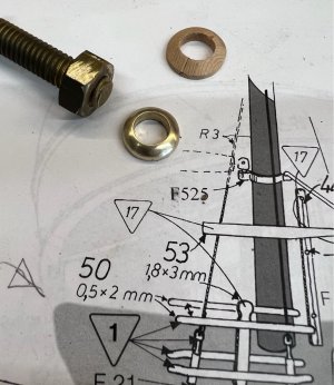
It looked way too shiny for the deck, so I put it in a container with vinegar and salt to age it a little. I then used the Dremel to drill some shallow holes underneath to help with keying the glue (did the same to the deck) and attached it using epoxy glue. Here it is installed, it looks a little large in that close-up photo, but with the mast stepped, it looks like a good scale fit.
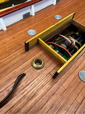
The mast will eventually be epoxied into the ring and deck.
Preparing for the mast
The kit design just has the mast attached to the deck with a forward stay and two shrouds per side that do have a degree of pull to the rear. Given that this model is likely to see more rough treatment than a static model, I’m a bit concerned about the deck attachment. If I’d thought about it earlier, I could have put something through to the keel but that’s not practical now. So, I thought that I could fashion a deck ring/collar to give a bit broader purchase and provide a deeper hole for the mast to sit in. The first attempt was with some very finely grained timber, and it looked good, but it split along the grain when the mast was pushed in to test fit. After some thought, I decided to have a go at fashioning something from brass. Now, I don’t have a lathe or mill, so I thought I’d try grinding down a large brass hex nut to a round shape and thin it down to a suitable thickness. With the nut locked onto the end of a bolt (with another nut), it was a pretty quick process. I then drilled the centre out to 8mm to suit the mast base, any lightly sanded it back to smooth.

It looked way too shiny for the deck, so I put it in a container with vinegar and salt to age it a little. I then used the Dremel to drill some shallow holes underneath to help with keying the glue (did the same to the deck) and attached it using epoxy glue. Here it is installed, it looks a little large in that close-up photo, but with the mast stepped, it looks like a good scale fit.

The mast will eventually be epoxied into the ring and deck.
More lights…
Before getting the mast in, I think it would be a good idea to finalise the forward lighting circuit because it’s going to get more difficult with the mast and its supports in place…this wiring feeds the mast lights, the lantern at the bow, and just lately I decided to add a light to the small skylight ahead of the mast. There’s a very small and simple change from the earlier circuit diagram as I’ve added an extra branch to the power feed that comes forward for the lights. This feed terminates under the skylight and connects the skylight light and the three mast lights to the supply…the fine feed wires coming down the mast were too short to go all the way forward to the planned termination.
The structure for the skylight was built back near the beginning of the build log. I added a small LED to the inside peak of the roof, that shines down toward the deck (I don’t what to see the light source directly). Then, inside the structure I added a sheet of white card about halfway down the wall to reflect the light back up and out the translucent glass…it also hides the deck and wiring underneath. It works very well.
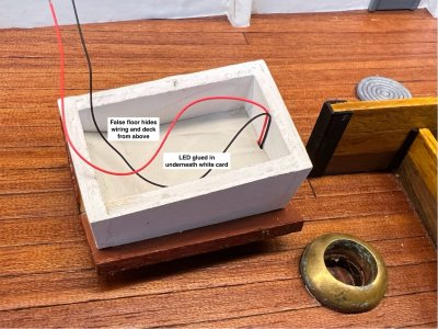
The wiring was fiddly because everything is short and very fine, but it came together as hoped.
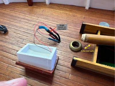
All the lights work as expected and I like the glow through the skylight. That leaves one light to be connected…the bow trawl lantern. That will get sorted when I add the forward structures in that area.
Next job...stepping the mast.
Before getting the mast in, I think it would be a good idea to finalise the forward lighting circuit because it’s going to get more difficult with the mast and its supports in place…this wiring feeds the mast lights, the lantern at the bow, and just lately I decided to add a light to the small skylight ahead of the mast. There’s a very small and simple change from the earlier circuit diagram as I’ve added an extra branch to the power feed that comes forward for the lights. This feed terminates under the skylight and connects the skylight light and the three mast lights to the supply…the fine feed wires coming down the mast were too short to go all the way forward to the planned termination.
The structure for the skylight was built back near the beginning of the build log. I added a small LED to the inside peak of the roof, that shines down toward the deck (I don’t what to see the light source directly). Then, inside the structure I added a sheet of white card about halfway down the wall to reflect the light back up and out the translucent glass…it also hides the deck and wiring underneath. It works very well.

The wiring was fiddly because everything is short and very fine, but it came together as hoped.

All the lights work as expected and I like the glow through the skylight. That leaves one light to be connected…the bow trawl lantern. That will get sorted when I add the forward structures in that area.
Next job...stepping the mast.
- Joined
- Dec 3, 2022
- Messages
- 1,547
- Points
- 488

Here it is installed, it looks...
...really really good!
Nicely done Pete, very creative. You didn't mention a lathe, how did you make it so perfectly circular?
Hey thanks, it was all done by hand on a very old bench grinder. Locking the nut onto a bolt helped (ie two nuts locked against each other) as I could just hold the shank of the bolt and rotate the nut against the wheel until it was round. I then did some finishing with it chucked in my cordless drill and sandpaper. The trickiest bit was drilling out the thread to the right size in my drill press…carefully held with vice grips (all very high tech!).Nicely done Pete, very creative. You didn't mention a lathe, how did you make it so perfectly circular?
A lathe is on my wish list, but I need to make some room in the workshop first…one day.
Hi Allan, thanks for the kind words…makes it all worthwhile when I think the log might inspire someone one day.I never gave a thought to building this type of vessel, nor wiring one, until seeing your work. Beautifully done.
Allan
Stepping the mast
Finally, the big moment…well, one of the big moments.
The first step here is to attach the chain plates. There are two per side and a couple of points at the bow, all related to the main mast. The items for attaching the shrouds are small punched brass strips, supplied in the kit. These must be bent to the shape of the hull and rubbing strake, add a hook, paint and glued in place prior to stepping the mast.
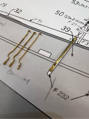
The plan shows the plates being bolted/nailed to the hull, and I’m sure they were in the original boats, but I don’t fancy putting more holes in my hull, so I cut the heads off a few small brass nails and epoxy glued them into the hole in the plates, making sure they didn’t protrude through. These were then painted in the hull top colour before installation. I stick small items like this to a piece of cardboard using upside down masking tape, so they don't get blown away when spraying them with a rattle can.
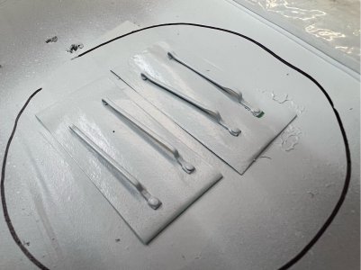
The angles to glue the chain plates were drawn on the hull by temporarily installing the mast with some cotton thread for stays. The plates were then glued using epoxy glue and it was allowed to harden up for a week prior to use.
Note: For other builders, if you haven’t already rigged the mainsail to the mast (as I did a few posts back), then at least add the sail mast hoops to the mast before adding the installing the mast as you won’t be able to easily install them after the mast foot is glued in place and the shrouds and stays are added.
How do you know what the angle is for the mast?
There is no guidance in the kit booklet, and there are probably many ways to do this, including using some type of adjustable protractor on the plan and the boat…but this is what worked for me. I set up the 1:1 side view drawing on a piece of thin MDF sheet and placed it directly behind the hull on the bench. I then jacked up the hull to sit at the correct angle (bow 5mm higher than the stern under the keel) and used a combination of sighting the side faces of the mast against the plan behind and also measuring the distance between the top tip of the main mast and the tip of the aft mast (it is mounted to the wheelhouse, so it is already set in stone). This worked well for me. Side-to-side was simply set with a square.
I used some cotton thread to temporarily hold the mast in place using one of the forestays, two of the shrouds and a line to the aft of the vessel to get the positioning. This was then eased off and epoxy glue added to the mast step (I had also pre-drilled the circumference of the mast base to get good glue penetration) and then everything was trued up again. It was a bit of mucking around, doing it twice, but it gave me confidence that everything would fall into place when the glue was added. I’d like to show you a photo of that, but this is one of the few things that I didn’t photograph at the time…just too excited, I guess! You get see plenty of it in future shots.
The mast was allowed to set for a few days before I touched anything. Then the temporary ropes were replaced one-by-one with the scale rope. Looking at the Billing photos, they used black ropes for the stays and shrouds, and I’ve done the same. I terminated these in the same way I used when I re-did the aft mast, the 0.5mm rope was CA glued to itself, then wrapped with fine black cotton thread with more thin CA to glue it all together. I think it looks good. The shrouds probably could have been done with a single piece of rope on each side (it looks like that on the Billing model…just looped through the top shackle), but I did mine as two individual ropes as I think the full-size vessel would have been rigged that way to provide some contingency in the event of failure.
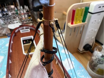
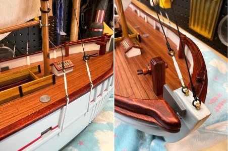
It's nice to finally see her with the mast in place. Next time I’ll take a look at the remaining rigging of the main mast…
Finally, the big moment…well, one of the big moments.
The first step here is to attach the chain plates. There are two per side and a couple of points at the bow, all related to the main mast. The items for attaching the shrouds are small punched brass strips, supplied in the kit. These must be bent to the shape of the hull and rubbing strake, add a hook, paint and glued in place prior to stepping the mast.

The plan shows the plates being bolted/nailed to the hull, and I’m sure they were in the original boats, but I don’t fancy putting more holes in my hull, so I cut the heads off a few small brass nails and epoxy glued them into the hole in the plates, making sure they didn’t protrude through. These were then painted in the hull top colour before installation. I stick small items like this to a piece of cardboard using upside down masking tape, so they don't get blown away when spraying them with a rattle can.

The angles to glue the chain plates were drawn on the hull by temporarily installing the mast with some cotton thread for stays. The plates were then glued using epoxy glue and it was allowed to harden up for a week prior to use.
Note: For other builders, if you haven’t already rigged the mainsail to the mast (as I did a few posts back), then at least add the sail mast hoops to the mast before adding the installing the mast as you won’t be able to easily install them after the mast foot is glued in place and the shrouds and stays are added.
How do you know what the angle is for the mast?
There is no guidance in the kit booklet, and there are probably many ways to do this, including using some type of adjustable protractor on the plan and the boat…but this is what worked for me. I set up the 1:1 side view drawing on a piece of thin MDF sheet and placed it directly behind the hull on the bench. I then jacked up the hull to sit at the correct angle (bow 5mm higher than the stern under the keel) and used a combination of sighting the side faces of the mast against the plan behind and also measuring the distance between the top tip of the main mast and the tip of the aft mast (it is mounted to the wheelhouse, so it is already set in stone). This worked well for me. Side-to-side was simply set with a square.
I used some cotton thread to temporarily hold the mast in place using one of the forestays, two of the shrouds and a line to the aft of the vessel to get the positioning. This was then eased off and epoxy glue added to the mast step (I had also pre-drilled the circumference of the mast base to get good glue penetration) and then everything was trued up again. It was a bit of mucking around, doing it twice, but it gave me confidence that everything would fall into place when the glue was added. I’d like to show you a photo of that, but this is one of the few things that I didn’t photograph at the time…just too excited, I guess! You get see plenty of it in future shots.
The mast was allowed to set for a few days before I touched anything. Then the temporary ropes were replaced one-by-one with the scale rope. Looking at the Billing photos, they used black ropes for the stays and shrouds, and I’ve done the same. I terminated these in the same way I used when I re-did the aft mast, the 0.5mm rope was CA glued to itself, then wrapped with fine black cotton thread with more thin CA to glue it all together. I think it looks good. The shrouds probably could have been done with a single piece of rope on each side (it looks like that on the Billing model…just looped through the top shackle), but I did mine as two individual ropes as I think the full-size vessel would have been rigged that way to provide some contingency in the event of failure.


It's nice to finally see her with the mast in place. Next time I’ll take a look at the remaining rigging of the main mast…
Main mast rigging
The mast is now up, but it needs a little rigging. The mainsail of this boat is gaff rigged. The kit provides all the blocks and attachment points to allow me to easily follow the 1:1 plan to understand how it needs to be set up. I had already installed the hardware before stepping the mast, I think it is easier. But I’d left the final ropework until I could see how the sail was going to sit on the model.
The Gaff
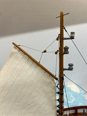
It's a pretty simple setup. I used 0.5mm scale rope for the rigging. They were terminated in the same way I’ve done all the others…thin CA to secure a loop, then wrap the glued ends in a finer rope (0.35mm in this case) and also seal that with CA. The halyard then runs down the starboard face to the mast to a cleat at deck level. After tying it off, I then tried to form some loops around the cleat as per the photos on the box. This was a bit tricky with the scale rope…it has a mind of its own when wound to a small diameter. I ended up progressively CA’ing it into submission.
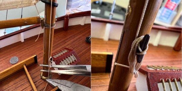
In later cases I cheated a little…I terminated the rope and cut it off as close to the cleat as practical, and then made a separate ‘set of loops’ on a piece of double sided tape and glued it on the cleat later. Much simpler.
The Clew
In the Billing photos it shows the clew of the mainsail as having a chain attached that passes through the boom and then has a rope (sheet) attached to the chain that terminates at a boom mounted cleat. My problem with this arrangement is that they don’t provide very much chain, and it is of a gauge that would severely weaken the boom if I drilled a hole to suit. My solution was to add a few links of a finer chain (the Admiral donated it) to the clew then tie on the sheet and pass that through the boom to the cleat.
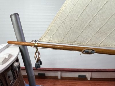
The Foot
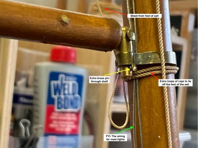
The plan doesn’t clearly show how this is supposed to be rigged. In the photos, it looks like the sheet is tied directly to the boom, close to the gooseneck. Initially I tried this, but it introduced another problem…the pin of the gooseneck is not constrained from being pulled out of its socket. So, applying some tension to the sheet just lifts the boom from its fitting rather than tension the sail.
Two solutions applied here…add a locking pin to the bottom of the pivot pin of the gooseneck. This will stop it coming out of the fitting. The gooseneck pin is brass, so a 0.5mm hole was bored in the lower section and a small brass nail used as a locking pin (with slight bend and a touch of CA to stop it falling out) …yellow arrows in photo. Works well.
And, the sheet for the foot of the sail was terminated by tying two loops of heavier rope around the mast (beneath the gooseneck fitting) and then tying off the sheet around those extra loops (red arrows in photo).
Mainsheet ropes to the wheelhouse
I’ve been back and forth on this one for the duration of the build. The issue is…being an RC build of a static model, I had to make the wheelhouse removeable for serviceability of the drivetrain. In the static model the boom is equipped with dual mainsheets and blocks, and these are attached directly to the raised floor of the wheelhouse foredeck. This would make removal of the wheelhouse difficult.
Originally, I was going to have all the RC switchgear under this section, and it would need to be lifted repeatedly on a sailing day, so I had decided to add a post on each side of the foredeck (attached to the main deck only) so that I could lift the wheelhouse. However, during the build I realised that I could put all the switchgear under the opening near the main mast (it has a simple lift off cover). So now the wheelhouse only needs to be removed for maintenance tasks for the drivetrain or rudder…i.e. infrequently. Consequently, the mainsheet pulleys/blocks will go back to the foredeck arrangement, but they will be attached with a hook on each block, rather than a fixed ring. This should make removal fairly simple on those occasions that it needs to be removed. Photo below…

I added a rope lead from the block attachment point to the cleat so that it still looks like it is tied off normally, but the mainsheet rope is actually terminated within the groove of the block. You'll also notice that I didn't connect the top two blocks directly to the boom fitting...because they then sit directly in front of the working wheelhouse floodlight. Adding a few lops of rope means that the light will be able to shine through to the deck.
Main mast is now complete, next time, the forward deck fittings and the trawl light.
The mast is now up, but it needs a little rigging. The mainsail of this boat is gaff rigged. The kit provides all the blocks and attachment points to allow me to easily follow the 1:1 plan to understand how it needs to be set up. I had already installed the hardware before stepping the mast, I think it is easier. But I’d left the final ropework until I could see how the sail was going to sit on the model.
The Gaff

It's a pretty simple setup. I used 0.5mm scale rope for the rigging. They were terminated in the same way I’ve done all the others…thin CA to secure a loop, then wrap the glued ends in a finer rope (0.35mm in this case) and also seal that with CA. The halyard then runs down the starboard face to the mast to a cleat at deck level. After tying it off, I then tried to form some loops around the cleat as per the photos on the box. This was a bit tricky with the scale rope…it has a mind of its own when wound to a small diameter. I ended up progressively CA’ing it into submission.

In later cases I cheated a little…I terminated the rope and cut it off as close to the cleat as practical, and then made a separate ‘set of loops’ on a piece of double sided tape and glued it on the cleat later. Much simpler.
The Clew
In the Billing photos it shows the clew of the mainsail as having a chain attached that passes through the boom and then has a rope (sheet) attached to the chain that terminates at a boom mounted cleat. My problem with this arrangement is that they don’t provide very much chain, and it is of a gauge that would severely weaken the boom if I drilled a hole to suit. My solution was to add a few links of a finer chain (the Admiral donated it) to the clew then tie on the sheet and pass that through the boom to the cleat.

The Foot
The plan doesn’t clearly show how this is supposed to be rigged. In the photos, it looks like the sheet is tied directly to the boom, close to the gooseneck. Initially I tried this, but it introduced another problem…the pin of the gooseneck is not constrained from being pulled out of its socket. So, applying some tension to the sheet just lifts the boom from its fitting rather than tension the sail.
Two solutions applied here…add a locking pin to the bottom of the pivot pin of the gooseneck. This will stop it coming out of the fitting. The gooseneck pin is brass, so a 0.5mm hole was bored in the lower section and a small brass nail used as a locking pin (with slight bend and a touch of CA to stop it falling out) …yellow arrows in photo. Works well.
And, the sheet for the foot of the sail was terminated by tying two loops of heavier rope around the mast (beneath the gooseneck fitting) and then tying off the sheet around those extra loops (red arrows in photo).

Mainsheet ropes to the wheelhouse
I’ve been back and forth on this one for the duration of the build. The issue is…being an RC build of a static model, I had to make the wheelhouse removeable for serviceability of the drivetrain. In the static model the boom is equipped with dual mainsheets and blocks, and these are attached directly to the raised floor of the wheelhouse foredeck. This would make removal of the wheelhouse difficult.
Originally, I was going to have all the RC switchgear under this section, and it would need to be lifted repeatedly on a sailing day, so I had decided to add a post on each side of the foredeck (attached to the main deck only) so that I could lift the wheelhouse. However, during the build I realised that I could put all the switchgear under the opening near the main mast (it has a simple lift off cover). So now the wheelhouse only needs to be removed for maintenance tasks for the drivetrain or rudder…i.e. infrequently. Consequently, the mainsheet pulleys/blocks will go back to the foredeck arrangement, but they will be attached with a hook on each block, rather than a fixed ring. This should make removal fairly simple on those occasions that it needs to be removed. Photo below…

I added a rope lead from the block attachment point to the cleat so that it still looks like it is tied off normally, but the mainsheet rope is actually terminated within the groove of the block. You'll also notice that I didn't connect the top two blocks directly to the boom fitting...because they then sit directly in front of the working wheelhouse floodlight. Adding a few lops of rope means that the light will be able to shine through to the deck.
Main mast is now complete, next time, the forward deck fittings and the trawl light.


