Howdy,
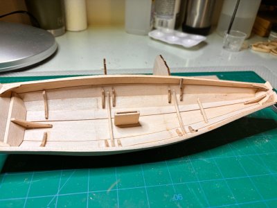
I've been remiss on starting this log. I've already finished the planking and will show some photos and make some comments on my experience so far. It makes much more sense to use this as a daily log, especially if encountering questions or mishaps, so as to get immediate feedback from the group. I'll try to do better. But, I have muddled along and have a decent looking hull (see below). I've found, again, that the instructions leave a bit to be desired; some things are not explained or even pointed out. I've tried to minimize my errors by reading the entire instruction set and researching other build logs, here and elsewhere, to avoid some common errors. Yet, I have still some concerns that I'll highlight here. I need to learn how the steps relate to one another, and that means sometimes WAY down the line.
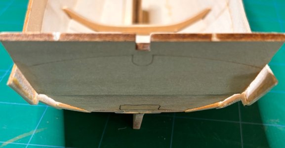
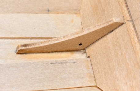
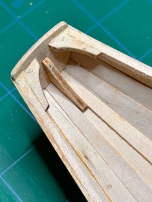
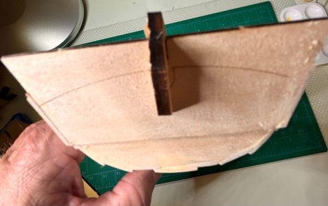
1. The stern transom knee floats above the finished bottom (see photo). This surprised me because I was aware of this problem from other modelers build logs and, indeed, when I laid the bottom planks it appeared to be snugged down where I thought it should be: along the bottom of the boat. But, as additional planks were added, the knee pulled up due to the bowing of the hull. This may have occurred because the transoms were not totally secure in the build mold; they were loose. I've seen in other build logs that modelers have buttressed the bow and stern supports and the molds (not glued the stern transom mold) so the transoms were firm and did not have 'play'. Upon reflection, a boatwright would have a very stable frame upon which to build his/her hull. Maybe I should too.
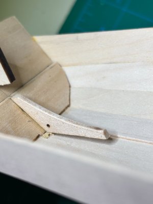
This inaccuracy would also mean that the angle of my stern transom may not be correct. I don't know how this might affect the build, but I will find out soon.
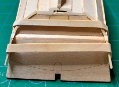
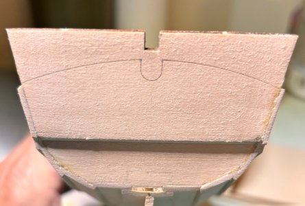
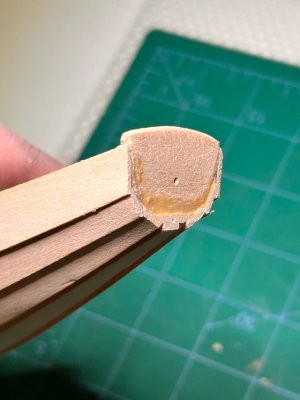
2. My second comment regards the laser lines on the stern and bow transoms. Are the sheer planks meant to join to the stern transom just below the laser line that will be used as a guide to trim the transom on page 18? My sheer planks join just above that line meaning I will need to trim my sheer planks in a very odd way and change the sheer line. This seems bad, very bad. Advice please. I'm hoping y'all won't say to remove all the planks with alcohol and re-plank, but I'm thinking you will. Gulp. This is where some more clarity in the instructions would have helped. Nowhere does it explain this, only that the planks need to be uniformly parallel.
Last comment today:
3. Another modeler on a different site reported that the templates on page 4 (of the instructions) used to locate frames inside the boat, are not 'true scale' to the build (1:12) and require resizing to insure accuracy when installing the frames. Same is true, he claims, for the figures on page 5 of spars and oars. Indeed, if you download the pdf version of the instructions from Model Expo and print them, they are larger (~10%) than the templates in the hard copy manual included in the kit. Advice? Anything to worry about?
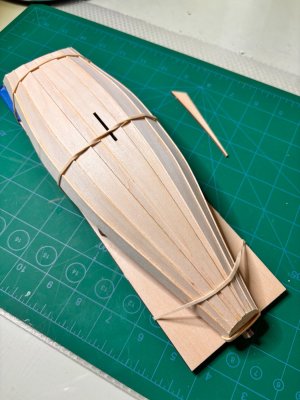
Thanks for reading this and I'll try to keep a real 'log' of my daily progress. Your advice is appreciated. BTW, here is my hull at present.
I've been remiss on starting this log. I've already finished the planking and will show some photos and make some comments on my experience so far. It makes much more sense to use this as a daily log, especially if encountering questions or mishaps, so as to get immediate feedback from the group. I'll try to do better. But, I have muddled along and have a decent looking hull (see below). I've found, again, that the instructions leave a bit to be desired; some things are not explained or even pointed out. I've tried to minimize my errors by reading the entire instruction set and researching other build logs, here and elsewhere, to avoid some common errors. Yet, I have still some concerns that I'll highlight here. I need to learn how the steps relate to one another, and that means sometimes WAY down the line.
1. The stern transom knee floats above the finished bottom (see photo). This surprised me because I was aware of this problem from other modelers build logs and, indeed, when I laid the bottom planks it appeared to be snugged down where I thought it should be: along the bottom of the boat. But, as additional planks were added, the knee pulled up due to the bowing of the hull. This may have occurred because the transoms were not totally secure in the build mold; they were loose. I've seen in other build logs that modelers have buttressed the bow and stern supports and the molds (not glued the stern transom mold) so the transoms were firm and did not have 'play'. Upon reflection, a boatwright would have a very stable frame upon which to build his/her hull. Maybe I should too.

This inaccuracy would also mean that the angle of my stern transom may not be correct. I don't know how this might affect the build, but I will find out soon.
2. My second comment regards the laser lines on the stern and bow transoms. Are the sheer planks meant to join to the stern transom just below the laser line that will be used as a guide to trim the transom on page 18? My sheer planks join just above that line meaning I will need to trim my sheer planks in a very odd way and change the sheer line. This seems bad, very bad. Advice please. I'm hoping y'all won't say to remove all the planks with alcohol and re-plank, but I'm thinking you will. Gulp. This is where some more clarity in the instructions would have helped. Nowhere does it explain this, only that the planks need to be uniformly parallel.

Last comment today:
3. Another modeler on a different site reported that the templates on page 4 (of the instructions) used to locate frames inside the boat, are not 'true scale' to the build (1:12) and require resizing to insure accuracy when installing the frames. Same is true, he claims, for the figures on page 5 of spars and oars. Indeed, if you download the pdf version of the instructions from Model Expo and print them, they are larger (~10%) than the templates in the hard copy manual included in the kit. Advice? Anything to worry about?
Thanks for reading this and I'll try to keep a real 'log' of my daily progress. Your advice is appreciated. BTW, here is my hull at present.


