Build Reference Documents

Both Paul and Poul have quite valid points re the representation of the "bolts".
I'm wondering where and when technical correctness and artistic licence apply and at what stage does one supersede the other.
The navy board models I referred to in an earlier post were constructed in such a way that representing most of the fastenings was virtually impossible. But they are quite exquisite and exude a real "atmosphere" rather than a cold but technically perfect representation.
But then again there are many many models that have both qualities.
And there my friends lies the true signs of a master modeler.
As you can see I'm still "at sea" regarding this matter. Your input would be most welcome I'm sure by all members of the group.
Cheers, Danielw
 
I'd like to add fastenings, not as much to make frames stronger, just for esthetics purposes. Howeve, Paul makes a very valid point about beveling the cant frames. What would happened if the taper line will cross bolts in the 'chock'? Hmm... Also, another concern, how the head of the bolt should be represented: flash with the timber or on top of it?
 
I'd like to add fastenings, not as much to make frames stronger, just for esthetics purposes. Howeve, Paul makes a very valid point about beveling the cant frames. What would happened if the taper line will cross bolts in the 'chock'? Hmm... Also, another concern, how the head of the bolt should be represented: flash with the timber or on top of it?
I'd guess the most correct would be simulated bolt heads on top of the timber. At least for the longitudinal bolts that should not be a problem but for the chuck bolt I think it depends if the holes can be drilled before beveling and the bolts mounted after final fairing (would sanding hide/close the holes?)
In case the bolts must be mounted before the beveling/fairing, I wonder if sterling silver wire could be used?. It is already gray and very easy to make black in situ, with liver of sulfur or eggs. It is a bit pricy but we don't need hundreds of meters.
 
Last edited:
Having beveled mine internally, it tends to make the joins dissappear on frames 16-6. They should re show up with a sealer applied.

I have tested with a .1mm black marker from officeworks and still not sold on the idea yet. Ill ponder further.

There could be an option to drill through from the outside once the hull is assembled, thread & cutoff. I dont know how much will be visible internally if you choose to add the cabins and partial top deck. External pinning view would make sense

I suppose it depends on a personal choice and that's what its all about in the end.
Its a bit like fully rigging a cannon that's hidden in the build. Only you know its there but no one else does.
 
okay here's my solution
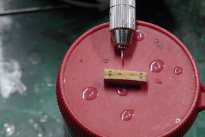
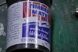
drill hole & fill with Ebony Filler. This way I can vary the size as needed & its does no compromise the wood as the hole is only 4mm deep and filled with wood filler. It sands pefectly and no residue or glueing of objects. I will drill & fill chocks before assembly of the Ribs. I have created a template for the drilling with some old S1130001.jpgS1130002.jpgdecking wood that is the same with as the Ribs.
 
Back
Top