CAUSTIC gun boat

PART 24

installing the knees

Ships built on the lakes in North America from the study of various ship wrecks show hanging knees were not used when building a deck. Lodging knees were used in most cases but not in every case. a system was used where the ends of the deck beams were set in a shallow notch in the deck clamp and a heavy waterway timber was place on top of the beam.
For the Caustic i did use lodging knees because the guns were so big and heavy for the size of the hull every bit of support would be needed to prevent the guns from ripping apart the structure.

The knees provided are over size and this was done on purpose because when a builder sets up the beams they may or may not be exactly in the right place. The knees is a fussy job of fitting them between the beams. So relax and take your time.

 
Thanks for posting this, Dave. Your videos and the timbering set, available from the Lumberyard, should permit even a beginner to build this model. I, for one, would like to see full plans for Caustic available, so the more experienced builder can do a full POF scratch build.

Hi Dave
i did get a few requests for a larger scale set of builders plans and that is something i will do as soon as i finish my current project.
 
PART 25

the deck is done all the beams and knees are in place.

Now a word about building in a jig.

Harold Hahn extended his frames and he used those extensions to mount the hull into the jig but there was also another reason for those extensions above the frames. Every hull has what is called a sheer line and this is a sweeping curved line that gives the hull its final shape. The sheer was and perhaps still is the pride of any shipwright its that sweet curving shape the hull has.
I have built hulls in and out of jigs with and without any extensions above the sheer. If you cut your frames to the sheer line that gives you no room to adjust anything, what happens in this case is you have to be exact with every single frame to make sure you hit that sheer level perfectly, that i will say is hard to do.
With the extra extensions above the frames you can now "cut" the curve of the sheer and get it perfect. The Caustic was pretty flat with just a slight sheer, This vessel was built with one thing in mind and that was extreme fire power and it's name was fitting Caustic.
A fun fact
if the Caustic fired all 3 guns at once the vessel would roll over from the recoil. so it was said

i will warn anyone using a saw on a Dremel HOLD ON to the Dremel and part the blade likes to grab and run off in any direction. a hand saw will take more time but a whole lot safer.

 
Hi Dave
i did get a few requests for a larger scale set of builders plans and that is something i will do as soon as i finish my current project.
Good to hear, Dave! I'd be up for 1:32 or 1:24 myself!!

One thing that would be fantastic is to have color coded bevel lines on the frames, so that rough beveling can be done off the model with a Dremel tool and sanding drum. Bob Hunt has done this with some of his kits and plans (AVS, Hannah) and it works well.

frame.jpg
 
PART 26

model ship building has a lot to do with consistency, hull construction is repetitive making everything line up.
When it comes down to finer and finer details you are not really working from drawings you are working the model. Setting that final height of the bulwarks starts at deck level and not trying to measure the outside of the hull.
Thinking about it you can not set the wales by measuring from the sheer line down if that line is not yet set. some builders will measure up from a base line which is the bottom of the keel. That works and you have to make sure your hull is setting level from side to side. Personally i measure up from the deck and set the sheer.

Frames on ships taper from the keel to the cap rail and it is important you have the top timbers at the correct thickness. in the video i used another on the spot trick to do that.

 
Dave

in the past i did not bother with bevel lines because all i did was work from over sized frame blanks and when i shaped the hull the bevels would just come automatically. This idea was based on Portia's idea to rough build the hull and like a sculpture shape the hull as one unit.
There was or still is two schools of thought on hull building one was to build each and every frame to the drawings and install a "finished frame" the other idea is to build frames close to the final size and shape them when they are installed into the hull. The second method is actually how real ships were built. a frame was assembled and set up in the hull and a team of carpenters would give the frame its final shape, this was called dubbing.
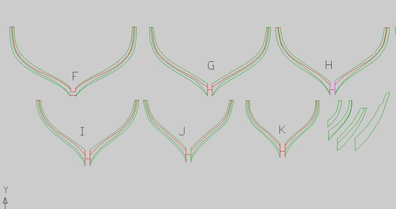
It was not until i got into 3D modeling where that bevel line became important, you needed it to shape each frame or at least provide a starting point where you can tweak the hull shape.
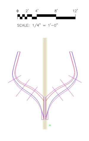
You can see this in the current project where the bevel lines are drawn in.

with the Caustic there isn't even frame shapes included in the drawings, building frames in the jig gave the shape to the frame and sanding the assembled hull is like the dubbing process.

bow4.JPG
 
As a designer i wanted to come up with a building project that made the process easier and try to eliminate problems. The idea is for a first time plank on frame builder to be able to actually build the model.
one problem with the Hahn method of building a frame blank and gluing on a frame pattern is the possibility of distorting the paper pattern when gluing it to the blank. When cutting frame pieces by hand also created an area for many tiny errors in assembly and cutting. This is very frustrating for builders.
Building the Caustic frames you lock the shape of the frames at 3 points at the keel and at the top of both sides of the frame. Here you eliminate the need to use a frame pattern, the shape is governed by the edges of the pieces because they are cut exactly the same by laser so the process of assembly is a touch and feel.
 
PART 27

This is all about bending planks and lots of clamps.

Most all plank on bulkhead kits are double planked for a couple reasons first of all because the bulkheads are space so far apart the planks tend to go flat between the bulkheads and secondly thin planks are easier to bend. But, wood can only go so thin before it looses its strength and thin planks tend to snap before they will take a bend. Bending planks takes a little finesse you have to play around with it. Sometimes a little heat is needed but most of the time just soaking the planks works fine.


PARTS 28 29 30 31 32

The cap rail

This series is about installing the cap rail but it is more about woodworking. My mentor Harold Hahn stresses the hands on method of model building, not that he disliked the use of machines but being an artist it was more about working the wood and teaching yourself how to use hand tool and he was never shy of having to make a part 2 or 3 or as many times as it takes to get it right. You can purchase a mill and do this work by clamping the wood in a vice and turn on the machine and away you go, a few passes and you have a perfect fit. Or you can pick up a knife and work the joinery by hand which this series is all about.

As i said from the start model ship building is about problem solving, how to approach any task to get results. In the case of the cap rail it is a timber that sits on the top of the frames, curves to the shape of the hull and has a slight over lap of the bulwarks inside and out.


PART 33

the title of the video is 34 but that is wrong it is actually 33 in the series and it is about decking.

In the video i had to custom fit a wider plank which involved cutting down a wide plank. This same method i used to taper planks when planking a hull.

 
These last two videos are about making the gun sleds. Again it is about hand cutting joinery this is to show you do not need fancy tools just a simple knife will give you expert results.


THE END

Well i hope you all enjoyed this video series and maybe picked up a hint or tip on model ship building

The next project is in the works maybe as another video series or at the least a build log. The next series will be going deep from research to drawing to design and into the build. See you then.


Back
Top