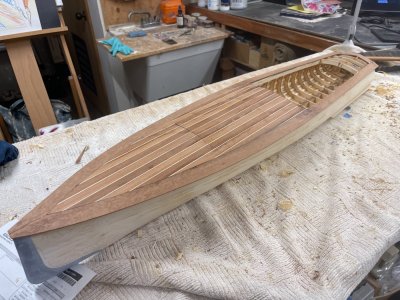
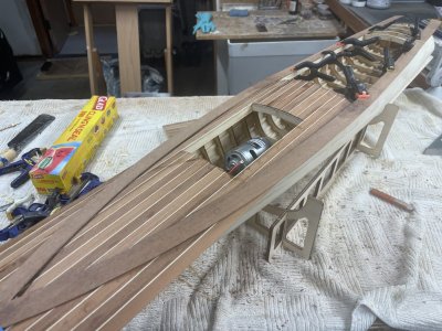
Charles Mower design #22 - a new approach to kit design

Joined
Dec 22, 2023
Messages
47
Points
58

Location
Montreal, Canada
I am working on a redesign of one of my frame sets and thought you might all get a kick out of a new approach I am taking.

In this design, the shape is created in a dedicated software that works well with organic shapes and then that part is inserted in one of the "usual suspects" for CAD for manufacturing.

But that is not important. What is fun is the resulting details that I have been able to introduce to contemporary kit design.

In this case, I have done the following:
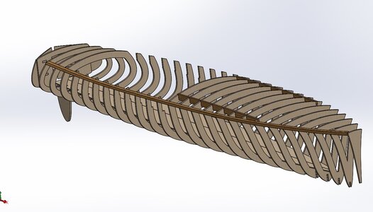
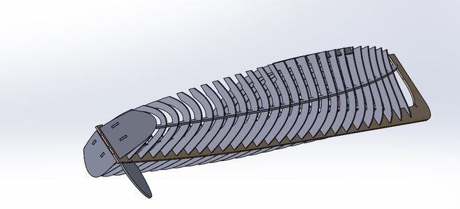
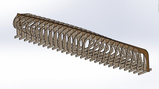
- doubled the number of frames that were in the original drawing. Remember, since I am working off of a 3D hull shape, I can add bulkheads wherever I want, and in any orientation.
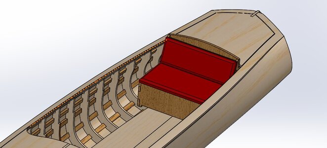
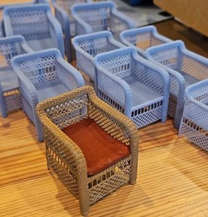
- opened up the cockpit area in preparation for including seats, fixed and 3D-printed, as part of the kit
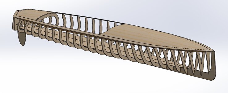
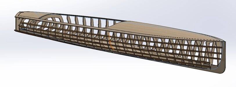
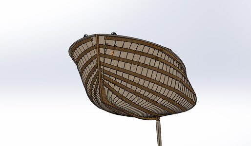
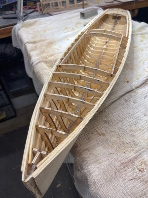
- added stringers to give the model builder a more accurate, and enjoyable, build.


This is an ongoing project. I will add a few more pictures later, as I get closer to cutting the parts.

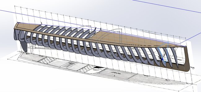
BULKHEADS-IN-PLACE-2.jpg

BULKHEADS-OPEN.jpg

FIRST-STRINGER.jpg

STRINGER-AND-DECK.jpg

STRINGER-POSITION-TARGET.jpg

STRINGERS-IN-PLACE-JUNE-11-2024.jpg
 
Hello All!
It's been a while since I posted what I have done with this model. I am surprised to see it has been more than a month!

Well, getting those stretchers to line up nicely was quite a challenge. I have to say, there's probable a solid twenty hours that went into trying a variety of features in the software to get this right.

The difficulties come from two things. First, the software doesn't "know" that I am cutting these parts from 3mm plywood. The second is that a hull shape does not twist evenly from the stern to the bow.

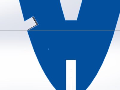
For the first issue, one cannot simply send a "cut" along some path to cut the notches in the frames. Such a path would follow a 3D shape and would cut the frames precisely along that path. That sounds nice but, of course, we don't cut the frames in 3D. They are cut on a laser on a flat surface. So, if we simply send a cut in 3D, when we lay the parts on the cutting table, the laser will see a whole bunch of lines where the cut goes through at some weird angle.

So, I had to figure out how to get that path to work, but the laser to know where to cut so the builder can install the stringers with the least amount of fiddling. Obviously, the builder will have to to some sanding to get the stringer to follow the shape of the hull, but the idea is to keep that to a minimum.

Also, when I did the first "insertion" of the stringers, they simply did not look realistic. I went through many, many iterations to get the look I wanted.

Now, we have a wonderful, revolutionary, method of designing and fabricating boat hulls!

I do not know how to rearrange the photos once they are inserted in the post. Can it be done?

In this first picture, we see a couple of these "cuts" that the software will do easily enough, but that do not work for what we are trying to achieve.

FIRST-ATTEMPT-AT-STRINGER-OPENINGS.jpg


In this second photo we can see the insertion of the sheer plank. The software will twist the plank along the path, but the twist is "even" all the way along, which is incorrect for a boat sheer plank. We need to figure out another solution.
FIRST-STRINGER.jpg


This picture is a bit out of order. It shows the stringers in place, with the notches all done, and it also shows a garboard strake that I have added. This plank does two things. First, it acts as a "landing pad" for the lower planks and it also strengthens the keel considerably.

GARBOARD-STRAKE.jpg


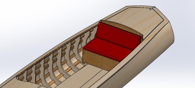
Another picture that is out of place. I am now building up the internal surfaces of the model. Here you can see the rear seat installed.

REAR-BENCH.jpg


The picture below is an interim picture. I was certainly not happy with the stringers following waterlines. That just didn't seem right, or realistic. I tried a number of strategies to work the stringers into a realistic arrangement.

STRINGER-1.jpg


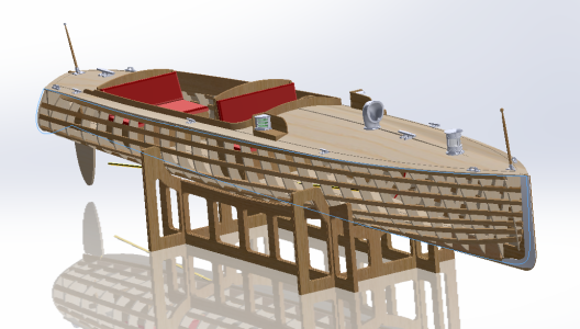
Finally, the stringers look pretty good!


STRINGERS-JULY-18-2024.jpg


Here is a nice bow-on view. You can see the smooth curves that the stringers will make once you build this model.

STRINGERS-JULY-18-2024-2.jpg


This picture show how many lines the laser would be looking at if we just used the cut path that the software wanted to use. I had to find a completely different strategy to make the cuts work properly.


STRINGERS-PROBLEM-WITH-CUT.jpg
 
Last edited:
Looks like you are getting it figured out and shaped up good.

It will be nice to see the boat when actually printed and assembled.
 
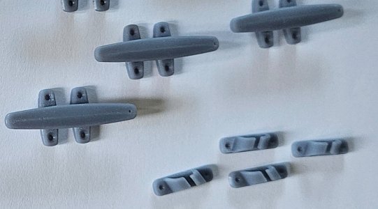
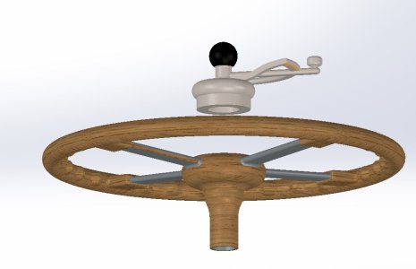
I have continued the design of this model. I now have some parts designed that will be 3D-printed and I have started the design of the T-rail. At 42", this will be a good model for those of us whose eyesight is weakening (and for those who want their models to go in the water).

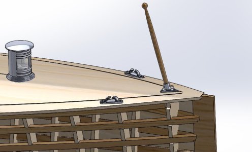
The first picture shows the T-rail positioning on your workbench. The second picture shows port and starboard bow chocks. The third picture shows the rear bench. The cushion will be up to you!

BULKHEAD-EXTENSIONS-JULY-31-2024.jpg

BOW-CHOCKS.jpg

REAR-BENCH.jpg
 
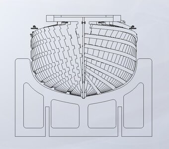
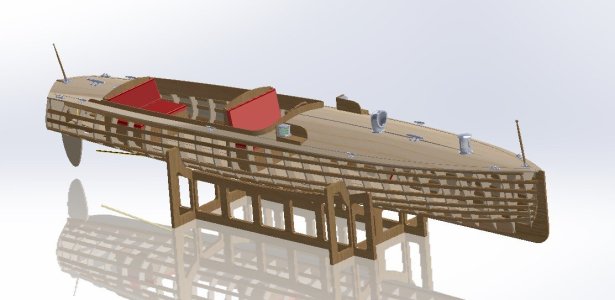
Now that I doing the laser-cutting layout, I am looking at various 2D views of the model. This picture really shows the interesting, twisting, notches for the stringers. Note the notches on the starboard side, and my 3D "stringers" on the port side. The basic kit does not include planking, although it does include several 3D-printed parts.
The picture also shows one of the parts of the cradle that will come with the kit. Since I design the cradles right off the 3D model, they fit very nicely.

VIEW-OF-NOTCHES-2024-8-2.jpg
 
Rick, are you able to describe the problem with the stringer notches a bit more, and what you did to work around this?
 
.​

Hi Rick,

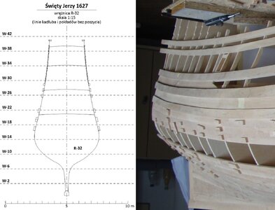
My post is no longer likely to help you, as you have actually solved yourself the problems associated with longitudinal battens notched into bulkheads. Nevertheless, let me show a similar solution used by professional museum modellers when building a 1627 ship model of my design.
I have provided them with hull cross sections in PDF format as in the example graphic attached below. Among other things, wales are always drawn on each cross section. The modellers, on their own initiative, took advantage of this circumstance by adding notches in the bulkheads for the wales (the latter had to be suitably thickened to accommodate this recessing).

It was only when the contours of the bulkheads had been modified by modellers in this way, still in the graphics program, that the final PDF files were submitted for CNC cutting into the plywood (strictly speaking, these were cut on a CNC milling machine, not on a laser cutter, but the perpendicularity of the cut to the table (and consequently to the flat material) is the same). One can partly see these recessed wales and notches they added in the attached photograph of the model under construction, although perhaps not very clearly.

I don't know how they took into account the inevitable perpendicularity (verticality) of cut in relation to the, after all, different angles of the wales. I suspect that they also applied manual retouching even later, already at the stage of assembly itself.

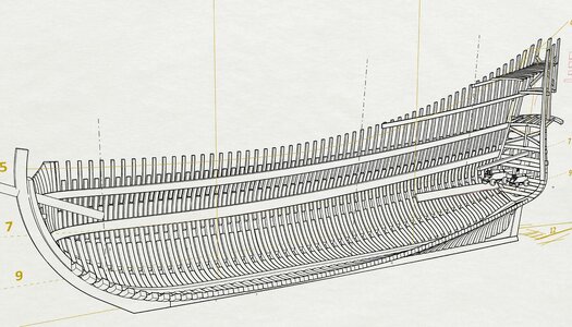
Similarly, you are already past the stage of defining the run of the external stringers. Having said that, it is probably worth saying that diagonals work very well in most such cases. However, due to the typical nature of ship hulls, usually not a single diagonal running from bow to stern, but two diagonals joining together at the midship frame, and set at different angles on the body plan. Sometimes light arcs instead of straight lines (in longitudinal projection) work even better, as you did. A typical effective trick is to set these diagonals more or less perpendicular to the surface of the hull (all the time in longitudinal projection), as much as possible.


Sankt Georg 1627.jpg


Święty Jerzy #1 (2).jpg

.​
 
Last edited:
these diagonals more or less perpendicular to the surface
Dear Kevin the Landlubber, and Waldemar,

The solution proposed is pretty well what I ended up doing but completely inside the software. It was very tedious and involved many iterations with a number of the software's features, before finally settling on what is, essentially, a manual solution.

In a nutshell, I sent the "cut" along a diagonal, as you noted above, but the twisting feature cannot be controlled "along" the surface of the hull. I cannot, for example, "twist" a tiny bit at the stern and then a lot at the forward three or four bulkheads. The software gives me an even twist from stern to bow.

This, of course, is not how a hull works. Planks run fairly flat in the stern area of a boat and then twist considerably as we approach the flare of the bow.

The first order of business was to figure out those diagonals. And, there again, there was plenty of mathematical fiddling until the only solution was to manually adjust the diagonals, one by one, until they looked right. This is pretty well what would happen in real life. You lay the plank against the boat and draw a line with a pencil. You then create the notches.

Once the diagonals were laid out, we get to the second problem, which you also allude to, and that is figuring out how to set the notches precisely perpendicular to the hull shape at each bulkhead. As I noted in a previous post, the software sends a cut right along the diagonal in question, but we cut 2-dimensional parts with the laser. And, also, the twist that the software gives is even from stern to bow, meaning the notches would never be quite right.

So, I created a shape for the notch and then manually placed it in the correct position, perpendicular to the hull, at each bulkhead. It was quite tedious, but I think the result was worth it.

Now, I am looking for modellers who would like to try out this revolutionary model!

Cheers,


Rick
 
Back
Top