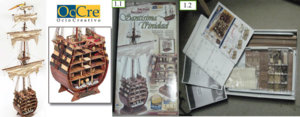
Cross section of the Santisima Trinidad at 1:90 OcCre kit #16800

Joined
Aug 16, 2019
Messages
870
Points
343

this one will close my ST project Ship, Launch and now Section
Santisima Trinidad OcCre kit #16800
Cross section of the Santisima Trinidad at 1:90

I start that kit in Mars 2004 and I was to do this kit simultaneously with the ship himself but as my older son want is ship to be the red 1805 Trafalgar version with copper hull I decided to build the cross section now and to built it as he want is ship, that way he will be able to decide if he like it or not. But as I got already 2 ships in constructions I will work on it occasionally only until I finish at least 1 of the 2 that are in their final step.
Ok lets start
First the box and the instruction
P 1-1, 1-2
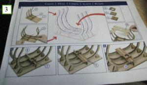
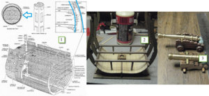
This is my second OcCre build and the box and the instruction are of the same quality of the first. The wood are well package and of very good quality the instruction come in 3. The first is a color booklet in 76 steps guide you for the build of the frame plus 2 more picture for the deck finishing and the mast. The second is the multi language book that follow step by step the color booklet (small note about the one that I got whit my kit was missing the French portion of it but I got 2 time the English one). The third is the scale drawing for the mast and the rigging.
Step 1 Is the build of the frame and went like a charm without any problem at all the instruction are clear and easy to follow
P 1-3
Step 2 - 4 The beginning of the interior lining
Step 5 - 6 Is the pose of lower decks beams and bottom beam rests here I did some modification as you can see on my picture 1-4 to 1-6 you will see that if I place that beam the way the instruction request I will have a small gap. So as per picture 6 I did small indentation in the beam and picture 7 is the result
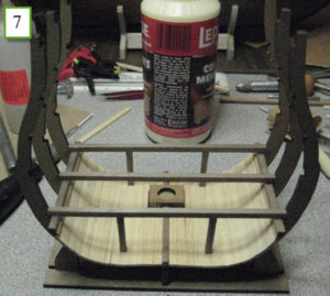
Step 7 – P 1-7 Is the finishing pose of the inside lining and the columns
1a.jpg1b.jpg1c.jpg1d.jpg
 
Step 11 Demand that you do a coat of varnish + a patina of age using an asphalt solution diluted with turpentine. What I did is first do a coat of waterborne varnish let it dry and then I did a chestnut wash the result is photo 2-1 to 2-3
Step 12 to 31 I just follow the instruction and the photo to build, install the Lower deck and the 1st battery deck. The instruction are very clear and easy to follow just to go slowly read the instruction and cut your pieces the way they demand.

Again a word of caution OcCre supply 2x3 in very short supply 4 length it is sufficient to do your build but you have to calculable your cut very carefully

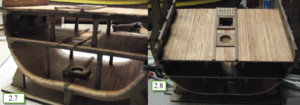
Also at Step 20 you have to install part 23 in the part list they are identified as Plywood there are no length of 2x3x90 in plywood. To be constant with the other deck those 2 part must be made in African Walnut, but they forgot to included them in theirs count of 2x3 so you are short of 2 length of 90mm. What I did I went in my box of spare wood and made 2 pieces with a 2 nice length of 2x5 that will be photo 2-4 to 2-8
Photo 2-7 show you the 1st battery deck install.
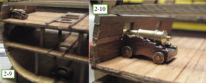
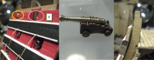
At this step I am stopping my build until I finish one of the 2 ship that are on the final stage of the rigging. Photo 2-9 and 2-10 show you the gun that are supply with the kit I have order new one to replace them.
I have found the armament and the size of the gun that was aboard the ST at Trafalgar in 1805
So until I received them I will not work on that project.
1a.jpg1b.jpg1c.jpg1d.jpg
 
The last time I post the first gun deck was finish and I was suppose to follow the instruction and build deck after deck but the armature are in a thick soft plywood that got a center made of a kind of balsa so they are very fragile.
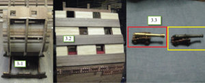
So I decide to jump to step 57 and build the outside hull to do that I install the Gun port side up to the third deck and install the exterior rubbing stake.
Photo 3-1 and 3-2
Next I did my first gun deck got a lot of fun preparing them I replace the original by the one that I have order they have the proper dimension and are of the proper calibre so prepare the pulley for them and the rope coil but they will be install later
Photo 3-3 to 3-6
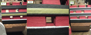
Now photo 3-7 to 3-9 after a lot of discussion with another member I decide to paint one side of the section now the coloring that my son chose is the red version (1805 Trafalgar) and I did a bit of coppering so that will you an idea of the final look
1a.jpg1a1.jpg1c.jpg1d.jpg
 
The gun of the first deck
First was my interrogation for paint of the inside of the deck I decided to go with Tamiya XF55 deck tan as I discover the inside was paint white beige to have light. I also paint the grating white and the battens black.
Those guns are not the one supplied with the kit, at that point I did some research as to install the proper gun for each deck and choosing the proper scale for each one so for the first gun deck it was the 36 ponder second deck was the 24 ponder, third deck 12 pounder and finally the forth deck was a mix of 24 pounder sea howitzer and 8 pounder gun
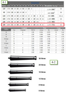
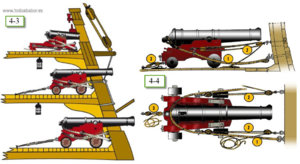
As I decided to rig the gun I was in the obligation to install the one of the first deck at this point. First I did some research as what armament and where it was install on the ship P 4-1 give the gun complement for 140gun in 1805 (Trafalgar) the more research to know how the Spanish where rigging there gun 4-3 to 4-4
Please be indulgent as those are the first one that I do, and here they are photo 4-7, 4-8 and 4-9 my first rig.
Photo 4-10, 4-11, 4-12 and 4-13 are something that I have seen in an illustration the pulley for the gun door. And I add a small coil of rope on a hook for the look.
Photo 4-14 to 4-16 are the complete gun deck. It is a bit sad that unless you look very closely you can barely see the work done.
So one deck done 3 more to go.

1a.JPG1b.JPG1c.jpg1d.jpg1e.jpg
 
Second deck completion
I have learn a lot about gun with that deck. I did know from the start that the guns supplied with the kit where not good for scale and I did not like them from the start so my intention from the start was to replace them with new one.
On the first deck the ST got 36pounder and according to some Spanish reference they where 3020mm in length so at 1:90 that give you 34mm they supplied 37mm and the one I install are 35mm so it went well
On the second deck we have 24pounder with a length of 2759mm that give you 30.65mm they supplied gun of 34mm so I went and got some very nice gun photo 5-1 of 30mm .
I paint one of them made some add on as a prototype and was happy with the result photo 5-2 to 5-6
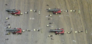
I try to displace the gun a bit forward, resign my self to use the original gun but with the new carriage and in the end I decide to build a new lower carriage and use the new gun. for wood I use popsicle stick to do it picture 5-10, 5-11 picture 5-12 the new complete gun and the original carriage, picture 5-13 all gun complete and finish.
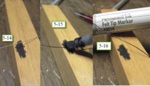
Picture 5-14 to 5-16 is a trick that I use to blackening rope I just use a black marker on the robe pass 2 time and got it and it give a bit of rigidly
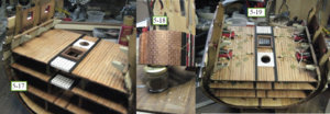
Picture 5-17 the second deck structure finish and 5-18 the coppering of the hull complete
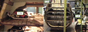
Picture 5-19 to 5-24 complete gun deck finish and complete
Picture 5-25 and 5-26 just to give you a look of the size the top deck will be at 7inch 80mm
The top mast will be at 20inch 51cm and not counting the rest of the mast

1a.jpg1b.jpg1c.jpg1e.jpg1f.jpg1g.jpg1h.jpg1c1.jpg
 
Gun for the third deck
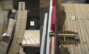
It is there that the problems start if you look at the photo 1 at the level of the second deck you will see that the wall of the ship is thinner at that point the kit wall is constant from the bottom to the top the total thickness of the hull there is 12mm and on top of it you have a 7dg vertical angle there photo 2.
Got 2 problems first the new gun carriage is a bit too high, second because the length of the gun on the carriage does not give sufficient length to make the end of the gun apparent on the hull. More research found a reference that show how the hull was build. So that made me think in all model all painting we always see all the guns sticking out of the ship ready to shoot away.
So what to do picture 5-9 is the original kit gun and the new one do not fit in the original configuration,
If you remember on my precedent log I mention the fact the gun supplied with the kit where not scale to the calibre of the gun.
On the second deck we have 24pounder with a length of 2759mm that give you 30.65mm they supplied gun of 34mm and they supplied the same gun for the third deck 34mm in length.
Now the allocation in gun for the ST at Trafalgar was 12pounder for the third deck those according to the Spanish record where 2194mm so at 1:90 that give you 24.4mm gun a big difference of 10mm
Photo 3 show you the difference between the 2 guns is the gun supplied and the nice Model shipways 25mm that I got you see the difference
Photo 4 for the positioning of them and the way they will look on the hull
So I have a problem, if you look at the picture 6 you see clearly the thickness of the frame that is constant from the top to the bottom.
Now photo 7 is what I will try. I will leave 2mm on the top + 1 extra mm to give a rest for the support beam of the forth deck that will remove 4mm out of the bulkhead and if I am not wrong as per photo 8 my gun will be properly place.
So wish me luck

1a.jpg1b.jpg1c.jpg
 
Small update for gun on deck 3
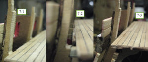
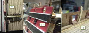
Well photo 7-1 is the cut of the frame it went very well I did not have any problem manly I think because the wood of the frame is very soft and easy to cut
Photo 7-2 and 7-3 are the deck at that place as you can see I was in the obligation to repair the deck and add new plank to complete the deck properly
As you see on photo 7-4 and 7-5 that improve the placement of the gun and the appearance on the hull
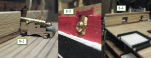
Finishing the deck wall 8-1 to 8-4
Ouf done

1a.jpg1b.jpg1c.jpg
 
As I am experimenting a lot with the cross section, let me show you what I have develop for the pulley
I use a black permanent ink felt tip marker on a 0.15mm cotton wire, the ink will penetrate the wire and will stiff it.
Step 2
Using a needle of 0.75mm I make a knot, and using a drop of CA glue I solidified the knot and got in the process a small loop
Step 3
Then I used that wire to put around my pulley
Step 4
Using those nail that are supply with some ship (I have a small jar of them like every body else I think) I cut the head and bent to obtain a small hook.
Step 5
Still using my felt marker I paint the hook and insert it in the gun carriage. After that I have just to pas the loop of the pulley on the hook.
I am using the same technique for single pulley where I need a loop on each side the felt marker give a light shine that can pass easily for metal.
For the first and second deck I have use 0.90mm galvanise wire for the hook of the pulley with a very big look that is really out of scale. On the first deck I have try metal wire for the pulley, for the second deck I have try something very similar to what I just put together.
Please if some one got a better method let me know as I will use that from now on, even for rigging as I do find that it give a nice look

1a.jpgStep 1
 
First thing I did when I came back from vacation is complete the rigging of the gun of the third deck 10-1 – 10-2,
But before I can install the floor of the forth deck I have to install the bulwarks and install the last rubbing stake and at least some of the lining 10-3 10-4.
I have to do that because I have to pass the rope that will keep the gun port open but that also implied that I have to finish and paint those parts before passing my rope.
Done paint of the rubbing stake complete the support install and forth floor in place.
I used the mast to make certain that all deck got a proper alignment 10-5 10-6.

1a.jpg1b.jpg
 
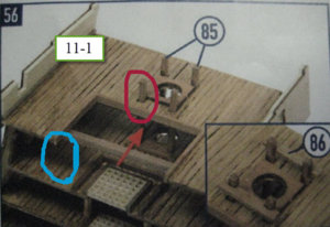
As I was putting in place the 4 pin rack posts parts 85 at step 56, I got a surprise 2 of the 4 holes where those posts are insert arrived smack on the edge of the center main deck beams by 1.5mm photo 11-1 in red.
I have check all measurement to see if I did a mistake but everything is properly place. At that time the deck was already in place and some inside lining install.
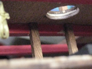
So after talking to myself for a few minute in different language I did some drilling and cut the beam to have the space to pass the post photo 11-2.
So if anybody build the section when you arrived at that step you will have to take that in consideration.
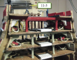
Now when I was wondering how to arrange those rack posts I realised that they did not put any columns to support the deck photo 1 in blue so I install 2 in the back and 2 in the front to follow the logic of the other deck photo 11-3.
But I also made some research and realise that all 3 beams are suppose to have columns so 6 columns on each deck in place of 4 but it is to late now.
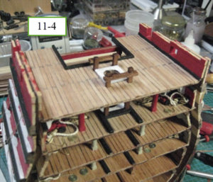
11-1.jpg11-2.jpg11-3.jpg11-4.jpg11-5.jpg
 
As I was waiting to received some part I decide to start to work on the mast.
And I found some mistake in measurement between the part listing for the main mast and the drawing
I did some cross checking with my ship drawing and made the proper correction
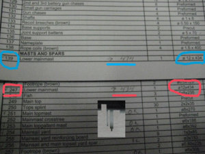
The mistake is on the Cross Section
The measurement of 434 is on the ship where the mast do not go the bottom of the hold
For the section it is 474 a good 40mm extra 12-1.jpg
I only saw the mistake because I was building both the section and the ship in the +- same time
 
As I was just finishing the top part of the lower main mast, I start to look at the parts that will be install on it.
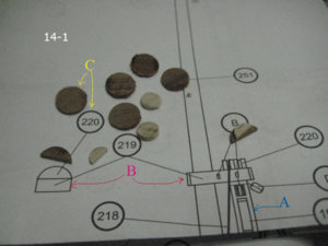
If you look at picture 14-1 you will see 2 part that go on the top the first one is 219 the lower main mast cap shore in red B
The second one is part 220 in yellow C they call that Cap shore
My problem is that on the ship part 219 or on the section part 149 they do not have the same thickness according to the drawing the one supplied with the ship is the proper one 5mm the other one is too tin by at least 1mm. At this sate I do not have decide if I will do something about it I have still to think about it.
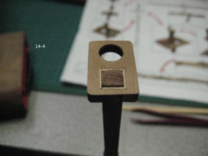
Same part another problem is the mast in blue A measurement taking there and also at other point give 6mm (in blue A) square for the mast the problem is that both prefab part supplied have a square of 7mm OUPS when I saw that it was to late the main mast of the section was already trim. So what I did is glue tin0.5 strip inside the square hole to reduce the size photo 14-4 now my mast fit perfectly the strip will not show as that part will be paint black. When I will do the mast for the ship later I will let that section at 7mm.
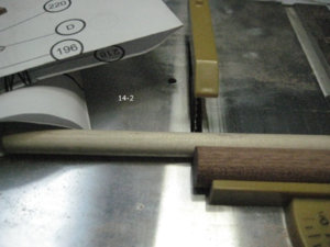
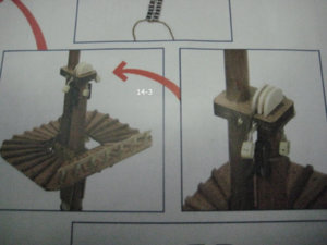
Now parts 220 for the ship part or 150 for the section, in the part list of the section they said to use 4x4x15 of wood in the parts list of the ship 5x5x15 now look how they show that part fit on 219 flush to the block then look at the photo 14-3 that also correspond to the measurement taken on the drawing 12mm so what I did photo 14-2 is cut thin disk of 1.5mm un some 12mm round left over from the mast cut them to the proper size and make a smaller one for the center I use 10mm for that part. I just have now to glue them together.

14-1.jpg14-2.jpg14-3.jpg14-4.jpg
 
After turning the lower main mast using my drill I was able to use my mini lathe.
And doing the other 2 parts was no problem at all
Picture 15-11 give you an idea of the height of the complete mast at this point both mast for the ship and the section are ready to be prepare.
Time to do the yard again the lathe is a wonderful tool that facilitates the work greatly.
The next photo will take you step by step and show you how I do them
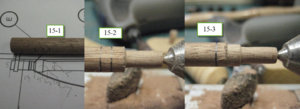
Picture 15-1
Using the 1:1 drawing I transfer the measurement on the wood and compare the length with the part list
Picture 15-2 and 15-3
Here I reduce the size to have the proper dimension
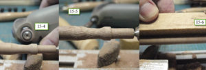
Picture 15-4 and 15-5
Here is a method that I use to have that curve section.
What I do is this I set the lathe to turn at medium speed and then I use my dremel at high speed to give the perfect curve
Picture 15-6, 15-7 and 15-8
15-5 using a sanding block ant the late at high speed I give the gradual measurement needed for the yard taking regularly spot check on the yard.
15-7 give you the first side complete at this point I turn the yard and do the other side picture 15-8 is both side done.
Both side take between 30 to 40 minute
Picture 15-9
All the yard for both build complete ship and section.
1a.jpg1b.jpg1c.jpg1d.jpg
 
The section and the ship supplied the fighting platform to be build with 1.75mm plywood and I did not like the finish look that will give.
So looking at how other did their, I look particularly at the one build by Andrea so after I decide what I want I read Mastini book and went ahead.
At hat point I have 2 platforms to build as I do both masts the section and the ship both the sip got a total of 3 platforms so I decide to do all of them.
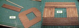
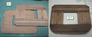
Photo 16-1
That is the plywood that I was suppose to use and that I discarded in my spare parts box using left over wood of 5x2mm I measure all the length to do my build and using my saw made all the cut photo 16-3 show you the rough build.
I then use again my saw to made a nice trim and I sand the final product photo 16-4. In the book of Mastini he show a trim to finish the platform and I like that so I add one photo 16-5
The photo 16-6 show you the drawing and the final platform
16-7 and 16-8 is before painting and after
The next step will be to prepare the lower main mast and I made the one for the ship in the same time
1a.jpg1b.jpg1c.jpg
 
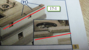
Since I have see the gunwales on the San Juan Nepomuceno made By Ksatsumoto I have the desire to do something nice for the ST it was not possible to do like what he did but I want to try something on my bench test the section.
So it was just a mater of the how to do it. The gunwales are made of piece of hard wood of 7x2mm. As per photo 17-1 I was suppose to just to make a small overlap of proximally 1mm the difference in height is 2mm not sufficient space to do very much.
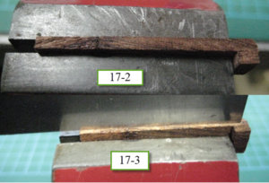
So what I did is this Photo 17-2 I glue a small piece of 2x3mm at the end of the piece and I extend the overlap distance to 3mm.
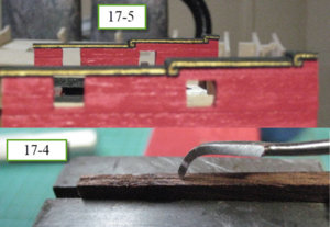
With a strait saw I made a dash photo 17-3 after that I use my diamond file to enlarge the line photo 17-4 a bit of dremel work some paint and the result 17-5
It is not perfect but I hope that when I will do them on the ship I will be able to improve my skill.

1a.jpg1b.jpg1c.jpg
 
At this point I have to start thinking to prepare to install the channel, the deadeyes and the chain plate, on all my previous build I just build them as the instruction without asking myself a lot of question.
But I think that this time I can at least try to improve the kit why not, and let you see the result.
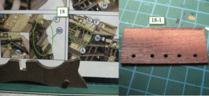
Photo 18 is what the kit suggest to build wire and chain and this is not accurate so after a lot of thinking I decide to change them
Photo 18-1 show the channel I have use them even if I don’t like them they are too tin I think. But I dint change them this time I will advise when I build them on the ship.
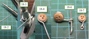
For the deadeyes at first I have use 20 gage galvanized wire and using my pliers and the bigger diameter I made 5mm circle photo 18-2 and 18-3 and 18-4 is the result
I finish them by making a small ring photo 18-6 the finish product 18-7 I then do all 10 deadeyes 18-8
Again using my pliers but the smaller diameter I did a first ring 18-9 using a block and 2 nails space at the proper distance 18-11 Photo 18-12 is the end result
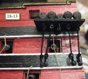
For the chain I just use a wire that I pinch at each end I paint the installation black and install them the finish is 18-13
I have a problem of constancy that will have to be solve when I will make them on the ship
And for the ship I found another solution and I did a better job

1a.jpg1b.jpg1c.jpg1d.jpg
 
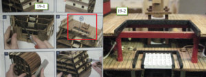
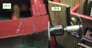
On this kit OcCre did not supplied any cross design 1:1 of the build only photo 19-1 is the only reference to cut and install part #92 waist beam the only measurement is the length of the beam himself no measurement as for the cut of the existing beam photo 19-2.
The drawing of the ship himself do not give me a lots of help as it is not build the same way.
So first I made some measurement and decide to do it that way I trace a vertical line and take a 5mm on the top and 2mm on the bottom photo 19-3
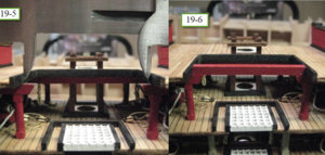
With some precaution I made my 2 cut photo 19-4 and 19-5
Then I cut the new waist beam install it and paint the result is photo 19-6 and with the 2 column that I have install previously it look good I think

1a.jpg1b.jpg1c.jpg
 
The installation of the ladder
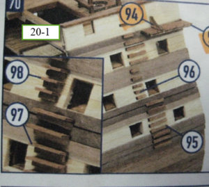
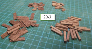
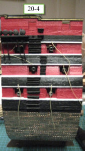
As you can see the only reference for those are one picture 20-1
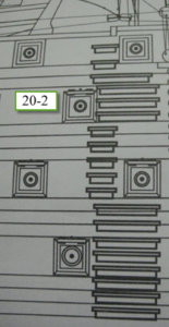
So I refer to the main plan of the ST and use those reference 20-2
I made the part and install them photo 20-3 / 20-4
One more thing done next making the gun port door

1a.jpg1b.jpg1c.jpg1d.jpg
 
Gun port door
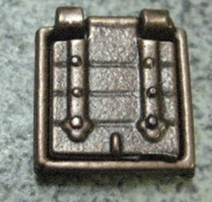
On the section I have the choice to use the metal frame and door but they are not even remotely accurate so I decide to build new one 002.
I need 2mm thick of wood on the section the gun port opening are 10mm 1mm of clearance on all side so I need a door of 12mm square
I have use Popsicle sticks they are 9mm x 115mm x 2mm Photo 21-1
First I made a cut on one side to have a nice straight border and repeat the operation on the other side and then made plank of 5mm in width Photo 21-2
The next step was to glue them 3at the time side by side to have 15mm plank Photo 21-3.
Now as some know the section is one model I have also the ship to build and anything that is modified on the section will be modified on the ship the ship need 108 door the section 12 so I need 120 doors
Each length will give me 8 doors so I have to make 14 lengths. I remove 1mm on each side and got all my length Photo 21-4
I made a small cut at one end then made cut of 12mm and equalise to have a nice 12mm x 12mm square Photo 21-5
After all the door are cut I sand nicely each one of them and the result is 123 doors Photo 21-6
The cut is only the first step I will now concentrate on the 12 doors of the section as the openings on the ship are slightly smaller 9mm I will need 11mm door it will be easy to just remove 1mm.

1a.JPG1b.jpg1c.jpg
 
Time to install the gun door lid
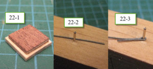
First I cut and glue a piece of plywood of 1mm in the back of the door what I have use are the part the are left over from the laser cut frame as they have exactly the proper dimension of the inside ( I will do the same when I do the ship ) photo 22-1
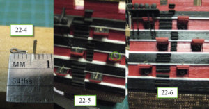
The second operation is making the small ring that will be use to attached the rope for opening the door.( I will have to make over 250 more of those as I will have 2 rope on the ship) For those I use a lead wire of 0.4mm I made a small ring around a nail and cut it with a length of 4mm photo 22-2 / 22-3 / 22-4
After it is just a matter of making a small hole inserting the ring then gluing the door too the hull passing the rope and place the hinge, for those I have use Model Shipways gun port hinge 10mm MS2554 final installation photo 22-5 and 22-6
Now the hull is complete next step is finishing all the deck equipment starting by the 4 last gun.

1a.jpg1b.jpg
 
Back
Top