Dutch heavy frigate ca. 1700 – engineering or carpentry ‘snowman’ making?

Joined
Apr 26, 2023
Messages
444
Points
323

Location
European Union
.​

Since existing publications, including academic ones, have actually been creating a Universe-sized research vacuum in the field of period ship design, particularly in the North Continental/Dutch tradition, for several decades now, it is worth taking a look at yet another design of Dutch origin, which I personally date to the late 17th and early 18th centuries and, according to design criteria, from an era before the widespread adoption of design diagonals, at least in the Netherlands.

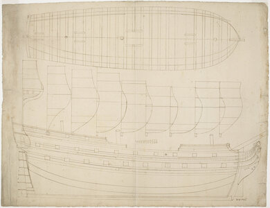
The design in question is that of a 114-foot-long heavy frigate, graphically designed for construction using the bottom-first method, as clearly evidenced by the two design lines characteristic of this method: the edge of the ‘flat’ and the ‘boeisel’ line, the latter separating the carpentry zones of bilges and sides of the ship's hull.

In the archival description, the drawing is dated 1780, which must be perceived as an obvious mistake. The square tuck stern, the short beakhead, the double wales, the double master frame (somewhat retrospectively here), as well as the (prediagonal) design method itself clearly point to the decades just around 1700, i.e. quite close to when van Yk's work on shipbuilding was published in 1697.

Link to archive and reproduction of the plan:

https://www.maritiemdigitaal.nl/index.cfm?event=search.getdetail&id=100199384


Oorlogsfregat van ca. 46 stukken, lang 114 voet - T670.jpg

.​
 
Great. One remark: a ship with over 40 guns is no longer called a frigate but a low charter man-of-war. Is the title 'frigate' originally added to the drawing or has some scientist been busy recently?
 
.​
Great. One remark: a ship with over 40 guns is no longer called a frigate but a low charter man-of-war. Is the title 'frigate' originally added to the drawing or has some scientist been busy recently?


Thanks for your comment, Ab, but how does this relate to the real essence of the issue? Anyway, I am going to stick with the term ‘heavy frigate’ as it best reflects the nature of the vessel, especially in universal terms, that is, against other fleets. I don't mind that for someone else it will also be ‘a low charter man-of-war’.

.​
 
.​

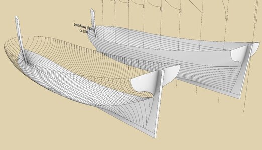
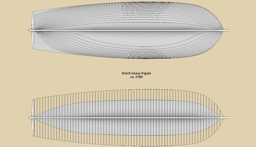
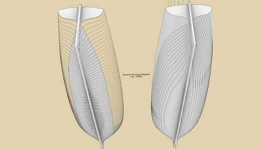
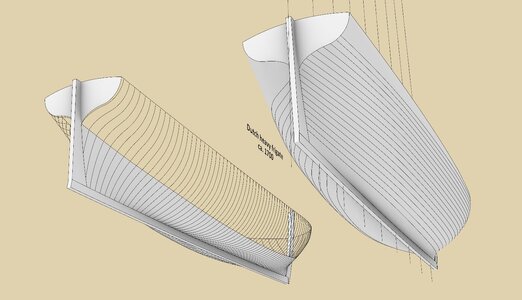
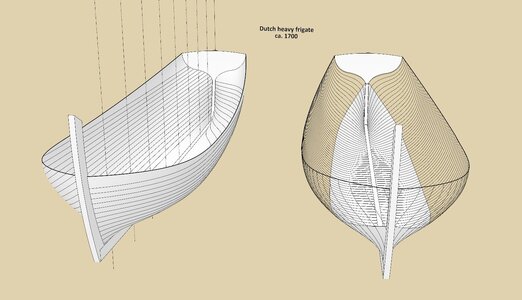
The renders below show the hull shapes of the Dutch heavy frigate ca. 1700 by using diagonals, waterlines and cross sections. Despite some concerns even before investigating the design method of this project, the resulting form can be considered very good in terms of its smoothness. Of note are only moderately sharp entry at the bow and also the run at the stern, as for a warship of this period.

Most interesting, though, is the conceptual method, which has not been described before. It is actually quite simple and the design sequence quite standard, nevertheless the result of this specific method is, among other things, the curved cross sections of the ‘flat’, which are hardly anywhere along the length of the hull straight lines as in other known designs. This should be clearly visible in the attached graphics, as well as in the original plan itself.


ViewCapture20240608_233500.jpg


ViewCapture20240608_233831.jpg


ViewCapture20240608_233953.jpg


ViewCapture20240608_234402.jpg


ViewCapture20240608_234709.jpg

.​
 
Last edited:
This looks like a nice hull somewhere in the transition between the almost flat bottom of the sixties and seventies and the more V-shaped hulls of later years.
I suppose you will explain next how the frames were drawn?
 
.​
This looks like a nice hull somewhere in the transition between the almost flat bottom of the sixties and seventies and the more V-shaped hulls of later years.


Now, I tend to see things this way too, but the reality must have been more complicated, because such an temptingly simple overall scheme is quite effectively disrupted by, for example, the Prins Willem 1651 model or the Scheurrak SO1 wreck from the late 16th century, both sporting very large deadrise.

In this context, it is a great pity that this scientist from the antipodes refused to provide me with scans of Dutch models from this period to examine from this angle, especially as he made these scans with public money. Sadly, his publications to date are devoid of relevant analyses of this kind, and simply scaling photographs lengthwise or crosswise to obtain a ship of different proportions can hardly be considered the vanguard of research methods, after all, or even correct methodology at all.

Against this background, this is a particularly good opportunity to thank you for your total openness in making the various materials available, on my behalf and I hope on behalf of many others. Also for the criticism, which I personally see as a necessary part of progress.


I suppose you will explain next how the frames were drawn?


Yes, of course, I will show all the most essential elements of the project, step by step, as in other threads. It shouldn't take long, as the project is really amazingly simple and effective at the same time. One might say, engineering simplicity at its best edition.

.​
 
Now, I tend to see things this way too, but the reality must have been more complicated, because such an temptingly simple overall scheme is quite effectively disrupted by, for example, the Prins Willem 1651 model or the Scheurrak SO1 wreck from the late 16th century, both sporting very large deadrise.
Both ships you mention are not reliable at all. The Prins Willem was probably made as a pond ship, which makes the hull shape questionable and the Scheurrak drawing was made years ago by a student on the basis of practically nothing. Scrap them both as reliable sources. Looking back you might be lucky for not getting the data from Australia. I had serious doubts about the whole project from the beginning. (which does not mean that the reality was not more complicated than we think. I'm sure it was, but let's please stick to reliable sources like these draughts, even not knowing the date of origin.)
 
For some time in high places rich people had models made to sail in their ponds. Some of them were even able to fire guns at each other.
Hello Ab, I find that piece of information truly fascinating. This shows that model building has been around for a much longer period of time than I ever imagined.
 
.​
the Scheurrak drawing was made years ago by a student on the basis of practically nothing

please stick to reliable sources like these draughts

Ab, so you no longer consider modern official publications by academics in this particular area to be reliable, like this archaeological study of the Scheurrak SO1 wreck?

Also, you advise me to stick to reliable sources, like this period plan probably unnoticed by anyone else, quite as if you haven't noticed that I've been doing this for a long time. Unlike various modern authors tending to just copy ideas from each other.


The Prins Willem was probably made as a pond ship, which makes the hull shape questionable

What makes you think that the Prins Willem model was intended to be actually sailed? It had, for example, ballast inside the hull or some other feature specific to floating models? Why the idea that floating models must necessarily have fancy hull shapes, different from the real thing?


even not knowing the date of origin

Do you have your dating of this plan? On what specific grounds?
.​
 
Last edited:
.​

Main dimensions / keel assembly / lengthwise division

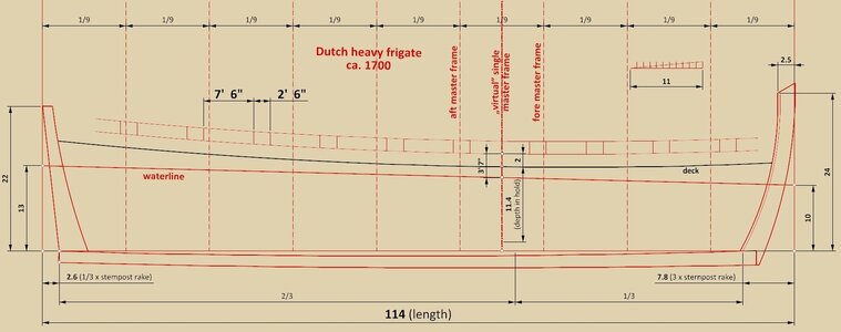
The sequence of the initial design phase is largely the same as described in the thread on the French heavy frigate of 1686, with the major exception that in this design the double master frame was already applied, as in the project of Dutch 72-gun ship described in the thread The Dutch 72-gun ship ca. 1690 – the apogee of Dutch ship design of the Classical Age | Ships of Scale:

– the length of the ship was determined by summing up the spacing between the gun ports, the width of the ports themselves (possibly 12-pounders), and their distances from both ends of the hull,
– the keel is realistically curved, which is later reflected in the process of forming the contours of the leading frames,
– the sum of the rakes of the two posts is 1/11 of the length of the ship, and their ratio to each other is 1:3, resulting in a very small rake of the stem,
– the length of the ship between perpendiculars has been divided into nine equal parts,
– the lengthwise placement of the double master frame has been set, respectively, at 3/9 and 4/9 of the hull length,
– the placement of the „virtual” single master frame, needed only for setting up the main longitudinal design lines (“flat”, max. breadth, top lines, decks), was set halfway between the fore and aft master frames, resulting in the greatest breadth of the ship at this single master frame; its longitudinal position falls very roughly at 1/3 of the keel length.
– the depth in hold value was set at a textbook 1/10th of the hull length,
– the level of the waterline at the (single) master frame was obtained by adding to the depth in hold the height of the gun port sills above the deck (here 2 feet) and then subtracting their intended distance from the water level (here 3 feet 7 inches). Finally, the design waterline was angled to a 3-foot trim.


ViewCapture20240610_091327.jpg

.​
 
.​

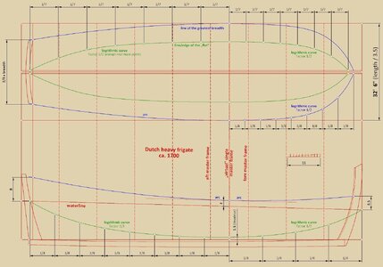
Line/edge of the ‘flat’ (green)

This line is the basis for shaping the underwater part of the hull. Deadrise (at master frame) is large and is as high as 1.5 feet, measured from the realistically curved keel. At the fore, the line of the „flat” terminates at the intersection of the perpendicular with the waterline, and at the stern post at the level of height of the tuck, which in turn has been also set at the height of the design waterline. For both halves of the hull, it is a logarithmic curve, in both projections, which translates into quite full, or maybe better round shapes.

Line of the greatest breadth (blue)

At the master frame, the distance of this line from the waterline has been set at a quite standard value of 2 feet. This distance is one of the most important factors affecting the lateral stability of the ship. In the sheer view, both arcs of this line are tangent to an auxiliary line parallel to the waterline (dashed line). It is perfectly parallel to the wales, or perhaps more correctly – the wales would be subsequently made perfectly parallel to this line.

* * *​

Of note is the very extensive use of logarithmic curves in this project. Contrary to the popular belief, it is one of the easiest curves to obtain, and no knowledge of theory is needed at all for their employment, just a familiarity with a straightforward division operation. For the same reason, logarithmic curves are also very practical and easy to use in real scale, for example to trace the contours of the frames without first drawing up a paper plan.


ViewCapture20240610_122031.jpg

.​
 
"Why the idea that floating models must necessarily have fancy hull shapes, different from the real thing?"

Scale sailing models do not float well. When you scale down a ship you run into the problem that the sails scale down as a square but the volume of the hull scales down as a cube so you wind up with way to much sailing area. You can reduce the sail area but that looks funny or you can try to increase the volume of the hull. It is common to kind of inflate the underwater portion of the hull to accomplish this. The other way is to attach a fin and bulb like America's Cup boats but that looks funny too.

PS- Yes, I do realise that you could wait for a very light breeze but the slightest gust will knock you over :)
 
Last edited:
Exactly, and the point is that in the old restoration reports there is mentioning of the fact that the keel was drilled on several locations, apparently to add weight or a false keel to stay upright in the water.

And about the Scheurrak drawing: I wrote to the archaeologist from the agency with who I am working on regular basis to confirm what he told me some time ago about how the drawing was created and why it has no solid scientific base, but he obviously had no time or opportunity to answer right away. Patience is necessary.

Oh, before I forget: calculating the length of a warship on the basis of the distance between the gunports is very well described in Leendert van Zwijndregt's book of 1755. You can find it in the translation of my book 'In Tekening Gebracht'I sent you some time ago.

Enjoying your thread Waldemar.
 
.​
Scale sailing models do not float well. When you scale down a ship you run into the problem that the sails scale down as a square but the volume of the hull scales down as a cube so you wind up with way to much sailing area. You can reduce the sail area but that looks funny or you can try to increase the volume of the hull. It is common to kind of inflate the underwater portion of the hull to accomplish this. The other way is to attach a fin and bulb like America's Cup boats but that looks funny too.

PS- Yes, I do realise that you could wait for a very light breeze but the slightest gust will knock you over :)

Great explanation, Don, except that it is exactly the opposite of this case, as the Prins Willem model has a very large (or increased) deadrise, reducing hull volume rather than increasing it. This way everything can be explained, just by not looking at the existing circumstances. Nevertheless, thank you for making the attempt. :)

.​
 
Back
Top