I'm having a tough time following your thread so I wondered if I was going in the right direction or not. 
-

Win a Free Custom Engraved Brass Coin!!!
As a way to introduce our brass coins to the community, we will raffle off a free coin during the month of August. Follow link ABOVE for instructions for entering.
-

PRE-ORDER SHIPS IN SCALE TODAY!
The beloved Ships in Scale Magazine is back and charting a new course for 2026!
Discover new skills, new techniques, and new inspirations in every issue.
NOTE THAT OUR FIRST ISSUE WILL BE JAN/FEB 2026
You are using an out of date browser. It may not display this or other websites correctly.
You should upgrade or use an alternative browser.
You should upgrade or use an alternative browser.
Dutch heavy frigate ca. 1700 – engineering or carpentry ‘snowman’ making?
- Thread starter -Waldemar-
- Start date
- Watchers 8
.
Exactly, and the point is that in the old restoration reports there is mentioning of the fact that the keel was drilled on several locations, apparently to add weight or a false keel to stay upright in the water.
Ab, it can be seen that you eagerly agree with Don's explanation, albeit a somewhat misguided one. I for one, however, will probably not be so enthusiastic about the explanation for these mysterious holes in the keel of the Prins Willem model. After all, we have experience from that unfortunate case of the Scheurrak SO1 wreck.
Oh, before I forget: calculating the length of a warship on the basis of the distance between the gunports is very well described in Leendert van Zwijndregt's book of 1755. You can find it in the translation of my book 'In Tekening Gebracht'I sent you some time ago.
I saw that you have also read my thread on the French frigate of 1686, but just to be sure, let me make a remind that on this particular issue, i.e. the calculation of the hull length, I refer there to Jean Boudriot's 1994 work. Your book was published in 2001. However, if you insist, I will also add the reference to your work if necessary. It won't be much trouble.
Anyway, while the issues you bring up here should be considered very interesting in themselves, they are only quite incidental to the intentional essence of this thread, quite clearly expressed in the title: Dutch heavy frigate ca. 1700 - engineering or carpentry ‘snowman’ making? In this context, it's a bit of a waste of space and our attention here. Perhaps a separate thread should be set up for these equally interesting issues?
.
No, I don't have the slightest interest in being referred to. However, if you insist, I will also add the reference to your work if necessary. It won't be much trouble.
I simply thought it might help you to stretch thee date of production of the drawing a bit.
Sorry for being in the way for you to continue your work. I'll shut up now.
.
It must be prefaced that the use of the conceptual method found in this plan of Dutch origin and presented below is not necessary for less demanding applications such as recreational construction of display models. Instead, the suggestion by scholars and well-known authors to mechanically copy the contours found on the original plans and then to proceed to smooth the hull shapes by eye can be used. However, this alternative method suggested by even the best experts in the field is unlikely to give completely satisfactory results in this case due to the rather significant drawing inaccuracies and distortions of the original drawing, which will most probably lead to the generating of the proverbial ‘snowman’. In addition, this method does not explain the design methods of the ships of the period and will not always be quite suitable for vessels of other dimensions or proportions either.
* * *
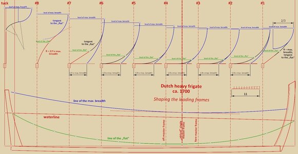
Shaping the leading frames
The sequence and method of determining the contours of the leading frames is straightforward and is naturally based on the main design lines previously defined, i.e the line of the ‘flat’ and the line of the greatest breadth:
– the lines of the ‘flat’ (red colour) were plotted first. For the central frames these are horizontal straight lines, for the two outermost frames #1 and #7 they are also straight lines, but connecting the keel to the line of the ‘flat’, and for the last frame #8 a circle arc is employed for a smooth transformation of the hull shape towards the sternpost,
– the futtock sweeps are then plotted (blue colour). For the central frames these arcs are brought to half the half-breadth of the corresponding frames. For the outermost frames, they are defined differently (see attached diagram),
– finally, the two sets of previous elements are connected by bilge arcs (black colour) in such a way that they intersect the line of the ‘flat’, while maintaining tangency on both its ends. For the exceptions occurring on the extreme frames, see the attached diagram.
Actually, so much for obtaining perfectly smooth shapes in a remarkably simple way. However, it can also be added that the best radius of the curve for the ‘flat’ in last frame #8 could also have been obtained at the very end of the design process, already after the ‘boeisel’ line had been determined and thanks to the use of this line.
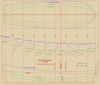
Finding the „boeisel” line
This line, except perhaps in the exceptional case of frame #8 mentioned above, was actually no longer of conceptual importance, although it could be practically useful to the carpenters directly building the ship, for the correct positioning of the frame elements and for dimensional control of the moulded hull shape. In this case, it was obtained by copying upwards the line of the ‘flat’ on the side projection (by about 3 feet 4 inches). Then, the coordinates of the points of its intersection with the already formed contours of the frames were transferred to the top projection and connected by a line. As can be seen in the diagram, this line does not separate the distinct geometric entities, but intersects both the futtock sweeps and the bilge sweeps.
As a general conclusion, I would also add that I personally do not see anything in this plan that could justify the claim of shipbuilding by eye. On the contrary, if one reads Witsen's and van Yk's work closely, as well as other documents from the period, such as business and legal agreements, it becomes clear that the information they contain must have had its origin in plans such as this (whether paper or mental). After all, even the customary formulae did not fall from the sky or were handed down by extraterrestrial beings.
That’s it. Thank you for your attention and participation (Ab, once again you tried to give me a hard time, o.kay
Waldemar Gurgul
.
Last edited:
.
Hi Ara, thank you. Well, it would not work as you suggest, and for two reasons. Firstly, in order to use the boeisel line to form the frames, it would first have to be predefined, even before the frame contours themselves, but the shape of this line on this plan of a Dutch 72-gun ship does not have any regular geometrical form, which is especially visible on the side projection. Secondly, even if this boeisel line was drawn in some haphazard way even before the frames, it would still not be possible to use it in some consistent way to form one particular set of geometrical elements of the frames. Sorry.
I would also add that a rather similar solution to the Dutch 72-gun ship is found in a French frigate from 1686 as well, which I should be showing soon.
.
Last edited:
bravo more please always more. have some questioms do not want to hog up your thread. god bless stay safe youn and yours don
.
to stretch thee date of production of the drawing a bit.
Highly unlikely it could go much beyond 1700 – square tuck stern, double wales, overall design simplicity without using even the corrective diagonals, let alone design diagonals. It would be already too much old-fashioned for the middle of the 18th cent.
.
The term "Frigate" was often used to mean many things into the early 1700s. It often meant a ship that was less than a Ship-of-the Line..
Thanks for your comment, Ab, but how does this relate to the real essence of the issue? Anyway, I am going to stick with the term ‘heavy frigate’ as it best reflects the nature of the vessel, especially in universal terms, that is, against other fleets. I don't mind that for someone else it will also be ‘a low charter man-of-war’.
.
Bill
- Joined
- Nov 4, 2020
- Messages
- 80
- Points
- 103

Highly unlikely it could go much beyond 1700 – square tuck stern, double wales, overall design simplicity without using even the corrective diagonals, let alone design diagonals. It would be already too much old-fashioned for the middle of the 18th cent.
The style of the plan is closest to those of Judicaer, that more or less places the dating on 1690-1700.
And yes, there were a lot of small 2-deckers referred as "frigates" in most of the European navies, it's more of a tactical niche than official classification.
I'm sure you are right Martes, but to the best of my knowledge Dutch frigates never had more guns than 40.
About the dating: all well, but the reasons Waldemar gives why the drawing has to be dated as early as 1700 do not seem very solid to me: square tuck sterns and double wales were still in use in all admiralties until after the first quarter of the 18th century.
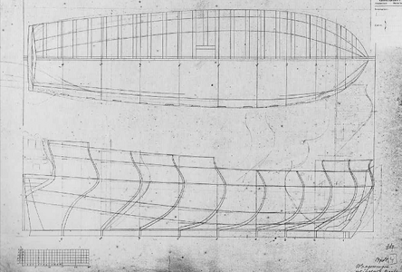
Here a drawing by Gerbrand Slecht, active on the Amsterdam admiralty yard from 1723-26:
Here a Rotterdam drawing of probably the first man-of-war that was actually built after preliminary drawings, the Twikkelo, built in 1725 by Paulus van Zwijndregt:
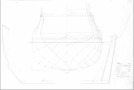
Both show a flat tuck, be it that the flat part was mostly above the waterline, which makes it basically not different from ships with round tucks.
As to double or single wales: both were used, there is a drawing by Leendert van Zwijndregt from 1757 showing double wales (sorry for the bad picture, my copying machine has its limitations):
Clearly double wales.
I don't have the skills to comment on the other characteristics Waldemar mentions, but for me there are reasons to date the drawing a few decades later.
Just my 50 cents, i don't want to criticize Waldemar's brilliant work.
(Pictures taken from my book 'In Tekening Gebracht' (2000), of which I have an English translation for anyone who sends me a PM.)
Ab
About the dating: all well, but the reasons Waldemar gives why the drawing has to be dated as early as 1700 do not seem very solid to me: square tuck sterns and double wales were still in use in all admiralties until after the first quarter of the 18th century.
Here a drawing by Gerbrand Slecht, active on the Amsterdam admiralty yard from 1723-26:

Here a Rotterdam drawing of probably the first man-of-war that was actually built after preliminary drawings, the Twikkelo, built in 1725 by Paulus van Zwijndregt:

Both show a flat tuck, be it that the flat part was mostly above the waterline, which makes it basically not different from ships with round tucks.
As to double or single wales: both were used, there is a drawing by Leendert van Zwijndregt from 1757 showing double wales (sorry for the bad picture, my copying machine has its limitations):

Clearly double wales.
I don't have the skills to comment on the other characteristics Waldemar mentions, but for me there are reasons to date the drawing a few decades later.
Just my 50 cents, i don't want to criticize Waldemar's brilliant work.
(Pictures taken from my book 'In Tekening Gebracht' (2000), of which I have an English translation for anyone who sends me a PM.)
Ab
Last edited:
.
Ab, I assure you that double walls and square tuck sterns also had ships from an even later time than in the examples you give, and indeed in the fleets of various countries, not just the Netherlands. The point, however, is to consider all the noted features together and not selectively. Because it is precisely this selective approach that does not seem solid and usually aims to prove a predetermined thesis. And it is apparent to the naked eye, even without an in-depth knowledge of ship design methods, that your last two examples, the youngest chronologically, are from a completely different world in a design sense, which is exactly what I am unwilling and unable to ignore.
But it is not even a question of some very precise dating of this plan. And completely irrelevant in this context is the argument about whether it is a small warship or a frigate.
What is relevant to the message of this thread is that this plan depicts a ship designed in an engineering manner. A ship, clearly intended to be built using a carpentry bottom-first technique, that is a method that in the modern literature and general consciousness to date has been seen as building the proverbial ‘snowman’, without plan or concept, mainly by eye. In this sense, it really doesn't matter anymore whether this plan was made in 1680, 1720 or some other year. I really don't know how to explain this more clearly, so as not to waste any more time on the frigate/not-frigate dilemma that is artificial here.
.
.
And as for your last example, it's not a double wale, it's a single wale made up of three boards, all marked by the letter ‘f’. This is also confirmed by other ship plans and photos of models by the same designer, also reproduced in your book.
there is a drawing by Leendert van Zwijndregt from 1757 showing double wales (sorry for the bad picture, my copying machine has its limitations):

Clearly double wales.
And as for your last example, it's not a double wale, it's a single wale made up of three boards, all marked by the letter ‘f’. This is also confirmed by other ship plans and photos of models by the same designer, also reproduced in your book.
.
Last edited:
Be convinced Waldemar that I know and understand the message you bring with this particular plan. The only thing I wanted to do is wipe out the (for me) questionable aspects in your title. I have seen too many titles for plans and works of art to believe what a scientist tells me. I have even sern a three-decker being called a frigate, obviously for no other reason than to use an 'insider' term. So interesting!
.
About the dating: all well, but the reasons Waldemar gives why the drawing has to be dated as early as 1700 do not seem very solid to me: square tuck sterns and double wales were still in use in all admiralties until after the first quarter of the 18th century.
Here a drawing by Gerbrand Slecht, active on the Amsterdam admiralty yard from 1723-26:

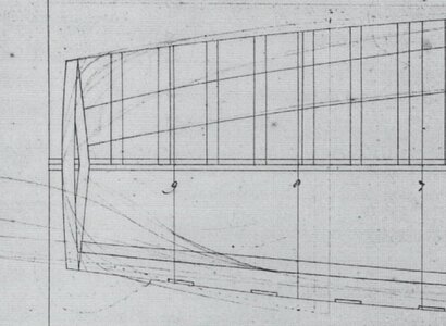
I also zoomed in on the section of the plan you give as an example of a square tuck stern and discovered the lines characteristic of a round tuck stern. These are the less pronounced lines rounding the corners at either side of the hull. Perhaps I should also analyse this plan more closely?
.
I would certainly appreciate that, Waldemar.
.
to the best of my knowledge Dutch frigates never had more guns than 40.
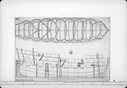
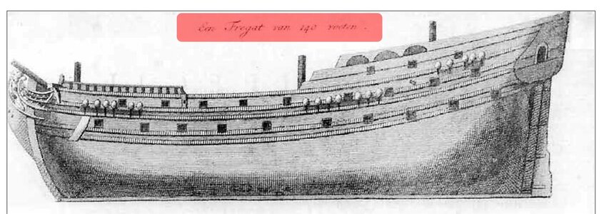
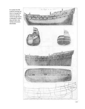
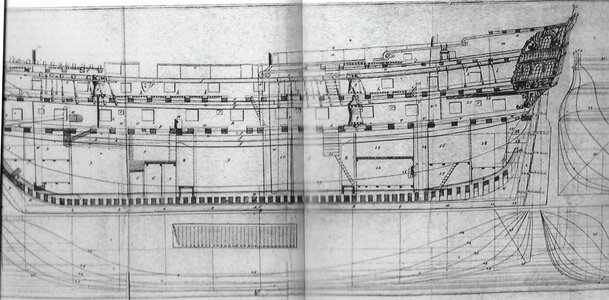
By the way, I have just come across another ‘Frigate’ with 46 gun ports visible and 140 feet long. It is taken from your book (page 133) and the plan itself dates from around 1700 too.
Full page:
.
.
Incidentally, this frigate drawn by Silo and shown above, as well as his plan of fluit from the same period, and Gerbrandt Slegt's design, and the plan of the Dutch 72-gun 'frigate ship' of around 1700, all of them also show ship designs intended to be built using the carpentry bottom-first method.
.


