Fast Response Cutter

Joined
Jun 20, 2024
Messages
154
Points
133

Location
La Porte Texas
I was not sure if I should share this build. I can’t say how it will come out. I would hope to have enough time to finish this one. I stopped working on the kit 2 years ago. I wanted to finish up the Sea Maid and the Hacker also the Trailways Stagecoach. That is what I have been doing in the mean time.

I have been inspired to get started again by the models I have seen being built here. The workmanship is fantastic.

Let’s see how far I can get.

The Dumas kit has some issues just like every other one out there. Does not matter who makes the kit. As builders we just have to make it better if we can. Sometimes the instructions conflict between drawings. This was the case with building the hull.

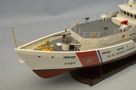
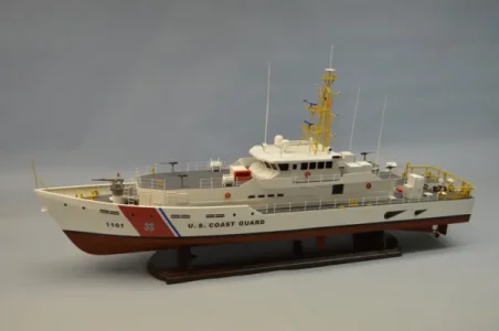
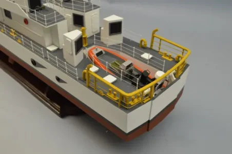
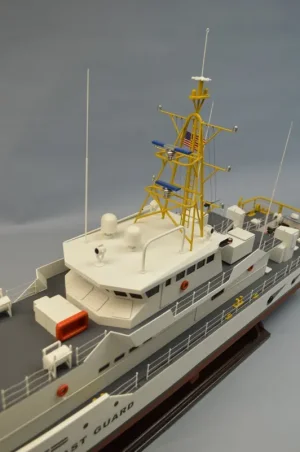
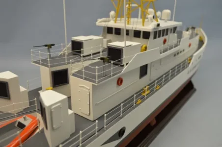
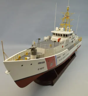
These are the Dumas photos of the finished kit. It makes a colorful model.
IMG_3961.webp

IMG_3960.webp

IMG_3965.webp

IMG_3964.webp

IMG_3963.webp

IMG_3962.webp
 
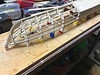
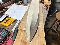
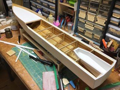
The hull framework is supposed to be built upside down. No problem right? I got the frame constructed without any problems. The issue came up when I went to fit skins to the hull. I had decided to save weight by switching from the kit supplied pvc to 1/16 plywood. This is a narrow hull with a large mast up top. That pvc material is soft and scratches easily. It is twice the weight of the plywood.

The plans show two different positions for the forward skins. The skins should be flush with the sheer. One drawing shows the forward skin above the sheer. This is wrong. The problem is that to fit the forward skin correctly you have to elevate the hull up off the building board. I cut the hull loose and got some Lego bricks and used them to give me clearance to plank the hull. This was an a pain to get set up but it worked out.

IMG_1602.jpeg

IMG_1601.jpeg

IMG_1611.jpeg
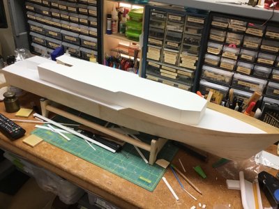
Here you can see the hull is upright and the forward skin is flush with the sheer. Note that the forward and rear skins are even at the joint. This is correct.
IMG_1605.jpeg
Here the hull is shown upside down and the center joint between the skins is not flush with the sheer.
 
Last edited:
Great that you started this building log of this model.
When I remember correctly somebody asked especially for experience etc. with this kit .......
 
Great that you started this building log of this model.
When I remember correctly somebody asked especially for experience etc. with this kit .......
 
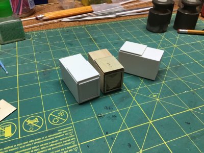
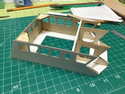
Next up was the main cabin. This was built upside down with the cabin roof as the base. There were a couple of fit problems at the stern but it wasn’t difficult to get sorted.

There is a left and a right for the stern walls. Make sure they are correct.

I have thought several times that I should change the structure to make it lighter. This is one of the reasons I set this aside.

IMG_1741.jpeg

IMG_1742.jpeg

IMG_1744.jpeg

IMG_1746.jpeg

IMG_1745.jpeg
 
There is a ladder on the rear of the pilot house. Dumas did not include any ladder for this detail.

This is out of order in the build sequence but I located these pics today so here we are.

I wanted to try and duplicate the ladder but I knew if I tried to solder brass together it would look like a raccoon on meth did it. I have always considered soldering to be a “black art”. You would think after all these years I would not have any problems.

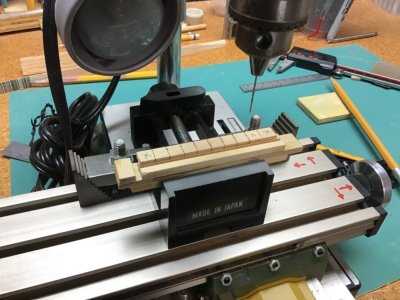
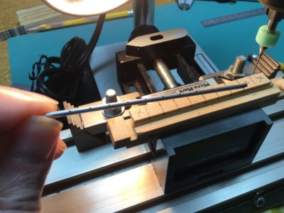
The solution was to use some small aluminum tube and drill holes in the uprights for the rungs. I made a jig to hold both tubes side by side. I hoped it would give even spacing for drilling. I just had to remember how many turns of the adjustment wheels I needed. At my age that is a trick. I made two ladders. The first one was too large but the second one was good.

The upper part of the ladder is attached with pins to the lower section. The ladder has some curved sections that took some time get a pair that were the same.

There are two belaying pin racks on the rear edge of the pilot house. Dumas had you bend a u shape wire to make these details. Since I had the jig set up I made the pin racks in the same way as the ladder. I got some brass belaying pins to fit in the racks.

IMG_1723.jpeg

IMG_1720.jpeg

IMG_1721.jpeg

IMG_1724.jpeg

IMG_1725.jpeg

IMG_1727.jpeg

IMG_1728.jpeg

IMG_1729.jpeg
 
There is a ladder on the rear of the pilot house. Dumas did not include any ladder for this detail.

This is out of order in the build sequence but I located these pics today so here we are.

I wanted to try and duplicate the ladder but I knew if I tried to solder brass together it would look like a raccoon on meth did it. I have always considered soldering to be a “black art”. You would think after all these years I would not have any problems.

The solution was to use some small aluminum tube and drill holes in the uprights for the rungs. I made a jig to hold both tubes side by side. I hoped it would give even spacing for drilling. I just had to remember how many turns of the adjustment wheels I needed. At my age that is a trick. I made two ladders. The first one was too large but the second one was good.

The upper part of the ladder is attached with pins to the lower section. The ladder has some curved sections that took some time get a pair that were the same.

There are two belaying pin racks on the rear edge of the pilot house. Dumas had you bend a u shape wire to make these details. Since I had the jig set up I made the pin racks in the same way as the ladder. I got some brass belaying pins to fit in the racks.

View attachment 472173

View attachment 472174

View attachment 472175

View attachment 472176

View attachment 472177

View attachment 472178

View attachment 472179

View attachment 472180
Wow, so far you has been doing a magnificent job, specially the ladder on the rear of the pilot house,Man you are a professional. Very good jod
 
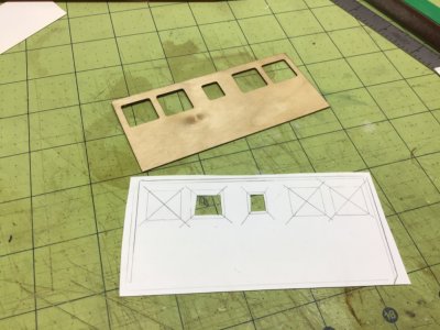
The pilot house was next up after the main cabin was completed. I decided to cover the plywood with 1/64 styrene. Adds some weight but it gives a nice smooth finish for painting.

IMG_1750.jpeg

IMG_1751.jpeg

IMG_1749.jpeg

IMG_1748.jpeg

IMG_1747.jpeg

IMG_1753.jpeg
If you look in the background you can see the pile of discards I made after building the window frames.
IMG_1766.jpeg
I painted the backside of windows with flat black paint. Do to my duffisoidal tendencies I managed to install two of them wrong way around. Had to be careful not to touch the shiny black windows. A finger print will not come off completely even after cleaning. I had to wear gloves to keep this from happening.
 
Last edited:
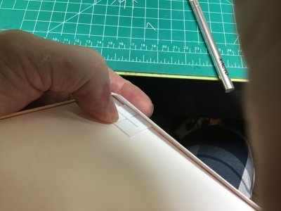
The edge of the pilot house roof is angled. It must be some kind of stealth requirement. The kit just uses a flat edge piece of trim around the perimeter.
It took two try’s to get the angle correct. The forward edge of the roof was a joy to fit. I added some supports to the back of the sloped panel. I had to make a jig to get the braces in place. My fingers were not going to fit.

image.png

IMG_1754.jpeg

IMG_1755.jpeg

IMG_1759.jpeg

IMG_1763.jpeg

IMG_1764.jpeg

IMG_1765.jpeg

IMG_1769.jpeg
 
Last edited:
Welcome aboard gentlemen. There is a large whip antenna on the cabin roof. The antenna can be laid backwards for clearance. There is a handle on the port side roof edge.

I wanted to add the wipers to the forward windows but I had to figure out a way to fasten them without smearing glue all over. I made a simple jig to get identical wipers. What I did was put a tiny bead of canopy glue to the blade and let it dry until it just turned clear. Then I had a jig to fit them in place. The canopy glue was tacky enough to hold them.

IMG_1823.jpeg

IMG_1665.jpeg

IMG_1773.jpeg

IMG_1780.jpeg

IMG_1781.jpeg
 
The mast is the most complex part of the kit. Dumas uses a wood and styrene mix to build the mast. Jigs are provided to help get things aligned. The problem is that the joints are not structurally sound for an operational model. Basically if you breathe near it the joints are going to fail. Secondly the mast is missing many of the details that you see on the real thing. I understand this is a compromise between realism and getting a kit to market at a reasonable cost.
These are some pictures of the mast as built by another builder. Not hard to see how the frame could be easily damaged. Butt joints are not going to work without some type of reinforcement.
I went a different direction with my mast.

IMG_4066.jpeg

IMG_4067.jpeg

IMG_4068.jpeg

IMG_4069.jpeg

You can see here how Dumas did the edge of the roof and the belaying points on the rear.
 
Last edited:
Back
Top