You are using an out of date browser. It may not display this or other websites correctly.
You should upgrade or use an alternative browser.
You should upgrade or use an alternative browser.
Looking good. It’ll all be covered up so as long as it’s symmetric, you’re good to go.
- Joined
- Mar 7, 2025
- Messages
- 32
- Points
- 48

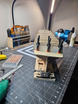
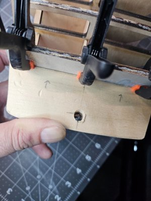
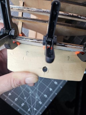
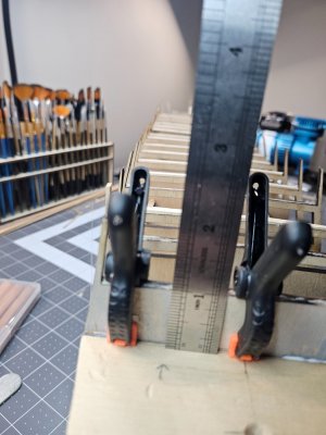
I'm waiting for tools I ordered. I sent onto the counter block and used Bob Hunts practicum. I did this by hand with a pull saw, chisel, and sandpaper. I've never created so much sawdust, wood shavings, etc. From that small block of wood. Anyway, I was very surprised that I built that counter block by hand. I don't think I would have been able to do this without the practicum. I had used the card stock templates and it made sense. When I glued it on, the practicum stated there should only be 1 inch from the top of BHD R to the top of the counterblock. Sure enough it was 1 inch and those clips cover exactly 1 inch when pushed all the way down. And the rudder was centered in the hole. I started the stern filler blocks and let me tell ya, by hand it's not so fun so far, but I'll press along and then next update will be after i finish the stern filler blocks.



- Joined
- Mar 7, 2025
- Messages
- 32
- Points
- 48

I decided to do the stern filler blocks. The tools I order, of course came after the fact. So, I took the leap of faith knowing that this was going to be painful doing it by hand from sawing the blocks of wood, using the templates and a chisel and lots of sanding until my hands fell off. I never thought I could pull this off and it took me roughly four hours to shape each block. I split this task in two days. I split the block of wood using a pull saw, which wasn't too bad compared to a standard wood saw. Anyway, I made the templates and traced it out on the wood while making sure they were oriented in the right spot. Because there was a lot of wood, I used the pull saw to cut the wood at different angles so that I was left with a piece of wood that was square and fit BHD R and the stern wall. You can see how I destroyed those blocks and left with the scraps seen in the picture. The amount of wood shavings and sawdust was baffling, almost inhuman an d I never thought this was possible, but I cleaned up after myself periodically. I was pleasantly surprised that I actually pulled this off by hand because I have ever handled wood this way. They fit well under the counter, BHD R, and the stern wall which I was thrilled to see because I thought I was going to totally mess it up, and there is no way I want to go through doing this by hand.
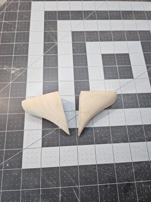
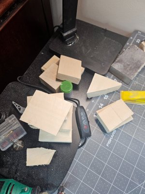

 d I never thought this was possible, but I cleaned up after myself periodically. I was pleasantly surprised that I actually pulled this off by hand because I have ever handled wood this way. They fit well under the counter, BHD R, and the stern wall which I was thrilled to see because I thought I was going to totally mess it up, and there is no way I want to go through doing this by hand.


- Joined
- Mar 7, 2025
- Messages
- 32
- Points
- 48

I'm not sure why the text got separated between the pictures...I'll move onto the bow and stern framework which seem a little intimidating, especially after reading the practicum that gave not a lot, but tons of detailed information which went in one ear and out the other. I'm old and slow and like pictures. Being a former Navy flyer, we like pictures...like a lot. I will attack this in chunks and keeping my fingers crossed that everything lines up and the planks actually fit.
Interesting to see what appears to be a set of Japanese woodblock carving chisels on your bench. My son had to get a set for school many years ago, which I still have.I'm waiting for tools I ordered. I sent onto the counter block and used Bob Hunts practicum. I did this by hand with a pull saw, chisel, and sandpaper. I've never created so much sawdust, wood shavings, etc. From that small block of wood. Anyway, I was very surprised that I built that counter block by hand. I don't think I would have been able to do this without the practicum. I had used the card stock templates and it made sense. When I glued it on, the practicum stated there should only be 1 inch from the top of BHD R to the top of the counterblock. Sure enough it was 1 inch and those clips cover exactly 1 inch when pushed all the way down. And the rudder was centered in the hole. I started the stern filler blocks and let me tell ya, by hand it's not so fun so far, but I'll press along and then next update will be after i finish the stern filler blocks.
View attachment 513893
View attachment 513894
View attachment 513895
View attachment 513896
View attachment 513897
- Joined
- Mar 7, 2025
- Messages
- 32
- Points
- 48

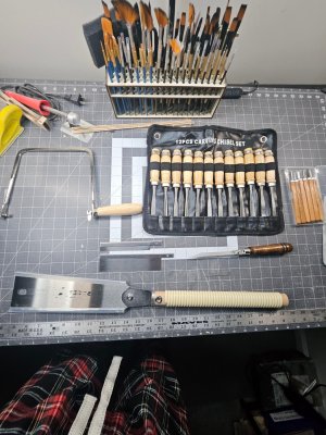
Yes, the Japanese imo create some of the best blades and cutting tools in the world. I found them to be incredibly solid and made extremely well and they have great sets for different budgets. The coping saw is Kikuri, the large pull saw is Kerye, the large carving set is Keenso, but I can't remember the brand for the 6 piece set that i got for beginners.Interesting to see what appears to be a set of Japanese woodblock carving chisels on your bench. My son had to get a set for school many years ago, which I still have.
Your Constitution is looking great.
Bill
Bill
I'm a bit late for the Welcoming Committee message, but nice to see you starting a build log and I wish you the best on your Constitution. As soon as I finish my Santa Maria build, the Model Shipways Constitution will be my next (and perhaps my last) build. In preparation of that build, I have been researching several other completed as well as ongoing Constitution build logs, not only here on SoS but there are several very good build logs on Model Ship World also. Do as much research and investigations as you can, as you run into concerns or stumbling blocks. Many times, others have had the same issues, which is the great thing about these build logs.
I had purchased Bob Hunt's practicum on the Bluenose that I built and, as well as his practicum was put together, I found myself referring to other build logs during my build process perhaps even more than the practicum. In other words, definitely use the practicum as another reference tool in this difficult build, but as only one tool in a very full toolbox of other available tools to refer to. I have also purchased his Constitution practicum in preparation of my build, but those who have built or are building the Constitution say the same thing about Mr. Hunt's Constitution practicum. Use it as one tool, but not an end-all-be-all.
Best of success on your Constitution build and I will definitely be following. Carry on, sir!
- Joined
- Mar 7, 2025
- Messages
- 32
- Points
- 48

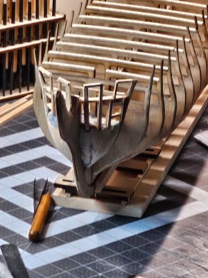
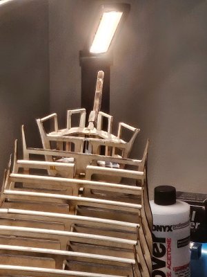
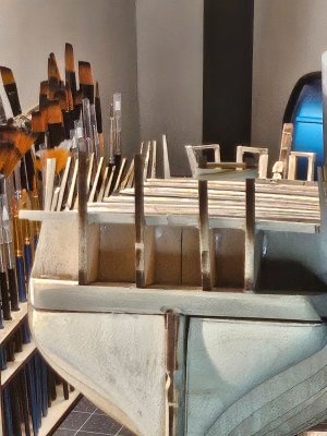
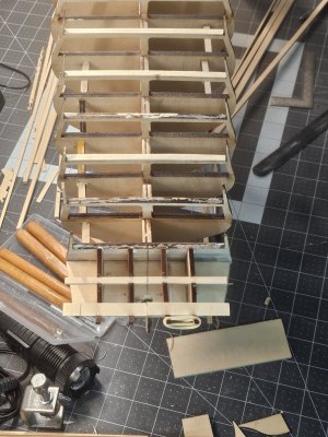
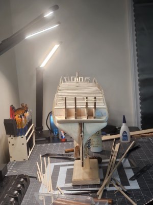
It's funny that the one thing I remember since joining this forum, is when someone said that the ship will look ugly until you get to planking. Boy were they right about that. I've made several cosmetic changes since the bow filler blocks while waiting for other tools to come in, so doing it all by hand is not so fun if there are machines and precision in play. Even when I take my time, I still make adjustments around adjustments I already made and it remains ugly...but when the measurements are where they need to be, not only does it baffle me, but also helps me remain confident that I can pull this off without eating too many crayons.I took my time the last few days battling the bow framework and was able to start work on the transom and get at least the main framework set up. With the gray filler putty I used on the back of BHD R to fill in imperfections after I had to reset the counter will make you go cross-eyed because it's almost like an optical illusion where it all looks off, yet the measurements line up like they should. Perhaps I should have gotten some spray primer to keep the color of everything uniform and cleaner like some of the previous Constitution modelers had done...it does look much better.


- Joined
- Mar 7, 2025
- Messages
- 32
- Points
- 48

I swapped out the vice fo holding the ship since my other one was stationary. So, I'm sure it adds to the distortion of my pictures taken with sheer precision, lol. Anyway, I should have the initial transom build complete. I've been following along Hunts practicum and I had to take a break because it got confusing following along what Bob is trying to say. After I made a couple mistakes, then I understood exactly what he was talking about...funny how that happens, plus the added bonus of lots of new nautical terms other than the ones I learned the past 30 years in the Navy before retiring. Well, that's it for now until I continue possibly tomorrow with the transom.
That's a good call. I picked up the same MSW fair-a-frame building slip a couple of years ago at an LHS going-out-of-business sale. Even heavily modified I found it to be virtually useless for anything other than as a keel clamp and it's not even very good at that. Now it mostly takes up space in the closet.I swapped out the vice fo holding the ship since my other one was stationary. So, I'm sure it adds to the distortion of my pictures taken with sheer precision, lol. Anyway, I should have the initial transom build complete. I've been following along Hunts practicum and I had to take a break because it got confusing following along what Bob is trying to say. After I made a couple mistakes, then I understood exactly what he was talking about...funny how that happens, plus the added bonus of lots of new nautical terms other than the ones I learned the past 30 years in the Navy before retiring. Well, that's it for now until I continue possibly tomorrow with the transom.
Rob looking at the photo taken above with the longitudinal view from the transom, I think I see a potential problems of alignment that will affect your decking. It appears that the bulkheads fore of the midship are canted to the left and subsequent decking will “hump” in that direction. Or possibly that your keel is twisted at that point. You might be able to unglue those canted ones and align them better. Otherwise, it will take a lot shaving and filing to level everything out. Of course, I can’t be sure if the photo is projecting the twist so laying a long straight edge in various locations might prove me wrong. By the way I thought the Fair-a-frame jig wasn’t;’t very useful other than a keel clamp for this size model. It works for smaller ones, though.I swapped out the vice fo holding the ship since my other one was stationary. So, I'm sure it adds to the distortion of my pictures taken with sheer precision, lol. Anyway, I should have the initial transom build complete. I've been following along Hunts practicum and I had to take a break because it got confusing following along what Bob is trying to say. After I made a couple mistakes, then I understood exactly what he was talking about...funny how that happens, plus the added bonus of lots of new nautical terms other than the ones I learned the past 30 years in the Navy before retiring. Well, that's it for now until I continue possibly tomorrow with the transom.
Welcome to the Forum, It is great to see another Constitution builder jump into the deep end of the pool. The Constitution is a rough build, but you will learn a lot about modeling during your build. Be sure to check out all the build logs on this sight. You will see all the problems builders have come across and how they solved those problems. Good luck and I look forward to following your progress.
- Joined
- Mar 7, 2025
- Messages
- 32
- Points
- 48

Thanks for the insight. Believe it or not, I suck at selfies and photos, lol. I did lay a long straight edge across the bulkheads and everything is level. I almost had to start all over again a couple weeks and actually get new bulkheads and keel assembly because when I laid down my straight edge, it was off. When I looked closer, all of the bulkheads looked higher in the middle of the part. I went back to Model Expo and put in a parts request because I thought I had to redo everything. They came back to me and said to lay the straight edge straight and not on an angle because the bulkheads were designed with the middle being slightly higher. So, I rechecked and sure enough, everything lines up as long as I keep the straight edge across the bulkheads in the same direction and not diagonal in any way. I've made minor adjustments because it appears some slight warping that I'm keeping up with, plus I live like right on the water. I can see in the picture the bulkhead in question, and I will investigate. I may need to shore up the bulkhead to equalize the measurements from one side to the other. But I've been fooled by the lighting because I have six different lights around the table for good visibility. Unfortunately, at different angles and shadows cast out there, I would panic and then when I got right up on the model, everything was normal and realized the illusion caused by lighting and taking pictures at an angle. I will however, recheck that bulkhead because I want the model to come out good and not like a banana.Rob looking at the photo taken above with the longitudinal view from the transom, I think I see a potential problems of alignment that will affect your decking. It appears that the bulkheads fore of the midship are canted to the left and subsequent decking will “hump” in that direction. Or possibly that your keel is twisted at that point. You might be able to unglue those canted ones and align them better. Otherwise, it will take a lot shaving and filing to level everything out. Of course, I can’t be sure if the photo is projecting the twist so laying a long straight edge in various locations might prove me wrong. By the way I thought the Fair-a-frame jig wasn’t;’t very useful other than a keel clamp for this size model. It works for smaller ones, though.
- Joined
- Mar 7, 2025
- Messages
- 32
- Points
- 48

I took a look last night at the bulkheads and they all measured the same on both port and starboard. I rechecked the shoring that I placed between the bulkheads to ensure everything aligned. I really do need take better pictures at proper angles and especially with the lighting. That bulkhead in question is darker from the laser cut than the other bulkheads and that seems to exacerbate what we are looking at. Anyway, I'll make better adjustments when taking the pics.Rob looking at the photo taken above with the longitudinal view from the transom, I think I see a potential problems of alignment that will affect your decking. It appears that the bulkheads fore of the midship are canted to the left and subsequent decking will “hump” in that direction. Or possibly that your keel is twisted at that point. You might be able to unglue those canted ones and align them better. Otherwise, it will take a lot shaving and filing to level everything out. Of course, I can’t be sure if the photo is projecting the twist so laying a long straight edge in various locations might prove me wrong. By the way I thought the Fair-a-frame jig wasn’t;’t very useful other than a keel clamp for this size model. It works for smaller ones, though.
- Joined
- Mar 7, 2025
- Messages
- 32
- Points
- 48

I'll be getting ready to create and install the waterways. I've been reading a lot from the modelers that went through this. However, there is one that stood out and I'm at a crossroads on which approach to take with the waterways. Going through Rob Hunt's practicum, before shaping the waterways, the wood needs to be beveled so that it fits neatly and flat to the side and top of each bulkhead. From the transom to BHD E it's relatively consistent and then BHD A, B, C, and D each have their own measurements. Another modeler, and an experienced one, took a different approach. Rather than physically beveling the wood, he instead measured the distance between each bulkhead and cut notches throughout that piece of wood, so that it fit perfectly into the bulkhead. The other side was the only side beveled, and even then, the bevel was pretty even because it did not need to equalize of compensate for the opposite side. I personally thought that it was not only ingenious but also look really good and professional and believe that his technique was brilliant. Before I make my decision, I wanted to get anyone's take on which approach I should take. Both ways require time with the exception of taking all of the measurements so each notch fits all of the bulkhead extension throughout the ship, which I will say I've broken many along the way and saved by the superglue.
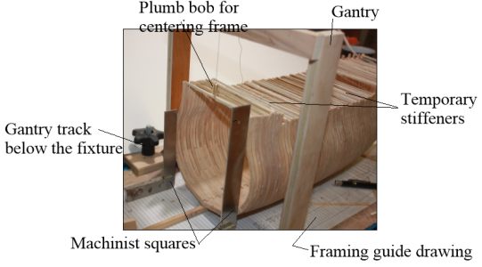
I am sure there are endless ways to do this so the keel and frames are square but doing like the shipyards still works. Below is a variation of one that I learned about in the basement shop of Ed Tosti, author of a number of ship model books. First up and a one time task is to make sure the worktable or bench is level and a long carpenter's square is a big help to confirm this. Next is to check that the building board is flat with no warpage. Attach the drawing of framing guide if one is available. I then rest the keel on the building board/ The building board has slots for the overhead crane to move along which can be used with a mini plumb bob and machinist squares for centering and squaring the frames. Pic and a thousand words..... There are also small blocks on each side of the keel fore, midships, and aft to keep it on the centerline but cannot be seen in this photo.fair-a-frame building slip a couple of years ago at an LHS going-out-of-business sale. Even heavily modified I found it to be virtually useless for anything other than as a keel clamp
Allan
- Joined
- Mar 7, 2025
- Messages
- 32
- Points
- 48

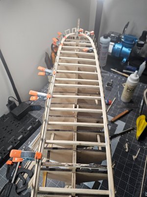
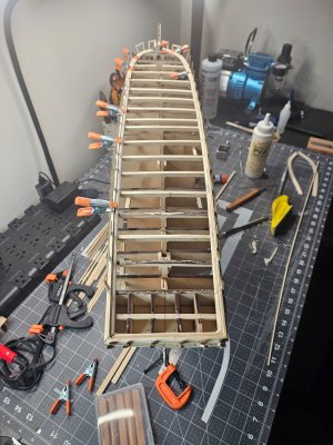
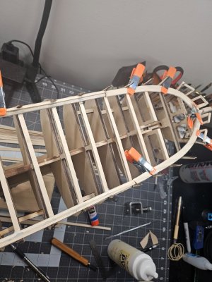
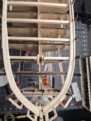
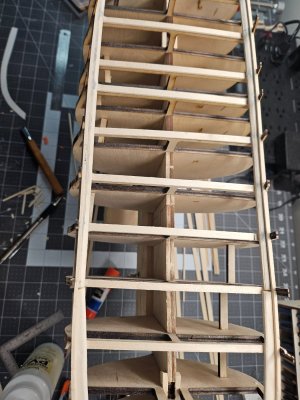
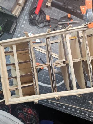
I just finished the waterway and planksheer. I did it over a 3 day period. It was challenging to say the least, but I'm very pleasantly surprised that it came out better than I expected. As with different phases before this, there was always something I had to redo or clean up the cosmetics, let alone my inability to take a good photograph. If I suck at selfies, than I suck at taking pictures of inanimate objects, lol. After several hours trying to synthesize what Hunts Practicum says about the waterway and planksheer, I actually found it a bit confusing to follow because you really have to do it in chunks. Also, it was hard to see some of the pictures so I could get a good view of what it should look like. I looked at what other modelers did and saw there were two wasy to do this.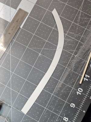


- Joined
- Mar 7, 2025
- Messages
- 32
- Points
- 48

Again, my pictures aren't perfect and most of the time probably not perfectly straight. Call it art; call it what you may. It stated the waterway from BHD E to the bow is slightly wider. Hunts Practicum shows to cut two piece for each side of the bow. Unfortunately, there were no sketches in the plans to make a template. The closest I got was on the 2nd page of the plan where I traced from BHD E to the bow and used the thickness depicted in the plans. So I had a good starting point, and instead of doing this in multiple pieces, I cut them out of basswood sheets I had extra on the side so I have enough wood for building the more challenging part like this, plus I didn't have to soak the wood in the water since I had cut out the shape. But I will say this much. It took me a handful of times to cut it out correctly without breaking it, like the 5 times I did.eventuall I prevailed. The port and starboard sides would involved a 5/16 wide strip of wood and the practicum had you bevel the side facing the decking. And then a bevel on the otherside because each bulwark extension were very slightly different in size, so bevel a little then line it up and keep beveling knowing that from BHD E thru the bow had different beveling specs.but low and behold, one of the Constitution modelers had an interesting way of installing the waterways without beveling, and instead cutting out small notches so that it fit almost around the bulwark extensions. I thought how clever, especially with the waterway this was not only genius, but looked very professional. So I went that route and in the end, came out better than I had expected and no misalignments, at least from my perspective and view from the sides and top. Lighting angles can be misleading and I look a little harder. This worked out well, and the planksheer was a piece of cake and fit perfectly with the bulwark extensions and the waterway. I did ask a few days ago in this posting for anyone's thoughts about beveling or cutting notches. I didn't see a response, so I chose and took a chance...I'm glad I did.


