French heavy frigate of 1686 - designing a ship in the Dutch(?) manner by graphic means

.​

Thanks a lot, folks. Peter, since it'll have to wait, you might want to make a copy of these threads – something strange is going on and the dysfunction of a mysterious cause continues to beset the thread https://shipsofscale.com/sosforums/...dutch-ship-design-of-the-classical-age.14013/.

* * *​

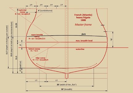
Master frame

The geometrical construction of the master frame of the frigate designed by Chaillé is exactly as given by Witsen in 1671, only with different parameters, more suitable for dedicated warships. The futtock sweep here is brought to half-breadth at the bottom of the design grid, i.e. at the level of the keel, as, for example, shown by Fernando Oliveira in his late 16th century works. ‘Softening’ bilge sweep also sports the most typical radius applied in warship designs, being 1/4 of the breadth. Truly, it would be difficult to find something even more classic.

Van Yk's 1697 work is virtually useless on these matters, as he was apparently not introduced to the arcana of strictly design, or did not wish to share them with his readers, instead shrewdly referring them in this matter to a recent publication by the French administrative official Dassié of 1677. He has probably unwittingly made the worst possible reference due to the rather theoretical, not to say fanciful, nature of Dassié's work in this regard.

It may also be added that the value of the tumblehome, set by the designer at 4 feet, is most likely a rounded quarter of a half-breadth, or 3.75 feet.


ViewCapture20240604_162813.jpg

.​
 
.​
HOW DO I MAKE COPIES OF THE THREADS

Don, certainly you don't mess up. Making safety copies is quite straightforward in this forum. Locate the three dots as shown below and select the "Export thread" option. Leave the default range 1–10000 as is. When done, print the outcome using the print function in your web browser. For actual printing, you may choose the so called virtual printer driver, such as Adobe PDF, in order to print the content to file, as opposed to making hard copies on paper.


Export thread.jpg

.​
 
.​

Shaping the hull

1. Forming the ‘flat’


In the North Continental/Dutch tradition, irrespective of the actual (in the carpentry sense) manner in which the vessel was built, the pre-determination of the hull shapes began with the formation of the bottom – the so-called ‘flat’. In the simplest terms, curves transversely connecting the keel to the line of the ‘flat’ were used for this, typically as straight lines or, if the hull forms were to be sharp, as arcs of circles. Sharper hull forms were particularly desirable at the stern (for all ship types) for better water flow and improved rudder efficiency, as well as at the bow for warships, to improve overall sailing properties such as speed and weatherliness.

In the design by P. Chaillé, for the extreme frames at either end of the hull, the radii of these circular arcs are quite typically (sub)multiples of the hull breadth. They are correctly selected, probably due to the experience of the designer, for smooth hull lines.

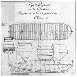
It can be reiterated that the process of forming the ‘flat’ (including the run of the line of the ‘flat’) is actually the most important and also the most ‘delicate’ stage of design, essentially determining the character of the vessel and its sailing properties. It is not without reason that it is the ‘flat’ that is shown as one of the fundamental conceptual elements in the following design of a French ship of the first rate from 1679 (French archives):


1679 - 1st rate ship of the line - project.jpg


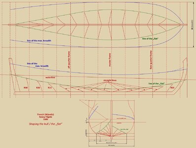
In the diagram below, the transverse contours of the ‘flat’ are shown in three conventions: as on the 1679 design above, as on the plan by P. Chaillé and as a classical body plan.


ViewCapture20240607_185009.jpg


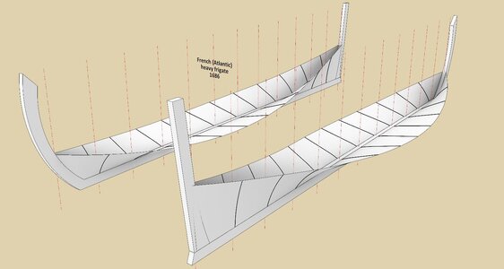
If the frigate designed by P. Chaillé had been built by the bottom-first method, the ‘flat’ at this stage of construction would have looked as in this graphic:


ViewCapture20240607_193539.jpg

.​
 
Last edited:
.​

2. Futtock sweeps

It could be said that the way of defining futtock sweeps in this French frigate is in some ways quite similar to the way employed in the Dutch 72-gun ship, described in the thread The Dutch 72-gun ship ca. 1690 – the apogee of Dutch ship design of the Classical Age | Ships of Scale, and both of these design variants are particularly well suited to shaping the hulls of ships sporting very sharp forms.

In this case, the procedure is somewhat less obvious, but also essentially quite simple:

– for the three central leading frames (master frame and both adjacent frames #1), the futtock sweep radius is the same, as previously defined for the master frame,
– for both frames #2, fore and aft, the radii are chosen so that these arcs are tangent to the „flat” line,
– for the frame #4 (the first leading frame from the fore), the radius is equal to 2/5 of the half-breadth of that frame,
– for the fashion piece the radius is equal to ¼ the length of the wing transom,
– finally, to obtain the radii of the futtock sweeps for all the other leading frames, auxiliary lines (black colour) have been applied, obtained by appropriately connecting with a straight line the lower quadrant points in two pairs of frames with futtock sweeps already determined (see diagram below). All arcs obtained are tangent to the level found by the intersection of both auxiliary lines with the corresponding vertical station lines.


ViewCapture20240624_233926.jpg


Exactly the same would have the following appearance in the form of a classic body plan:
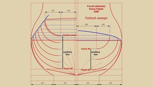

ViewCapture20240624_234148.jpg

.​
 
.​

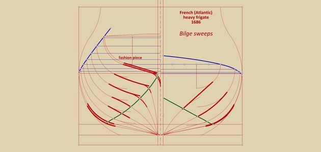
3. Bilge sweeps (thick red lines)

Strictly speaking, the softening bilge sweeps only occur in the three central leading frames (master frame and both frames #1), and are of constant radius equal to a quarter of the maximum breadth.

For the rest of the leading frames, these sweeps are more in the nature of curves (circle arcs and straight lines), simply connecting the 'flat' with the futtock sweeps, selected in a rather individual way, while ensuring faired surfaces of the underwater part of the hull. These curves are described in more detail in the diagram attached below.


ViewCapture20240625_170355.jpg


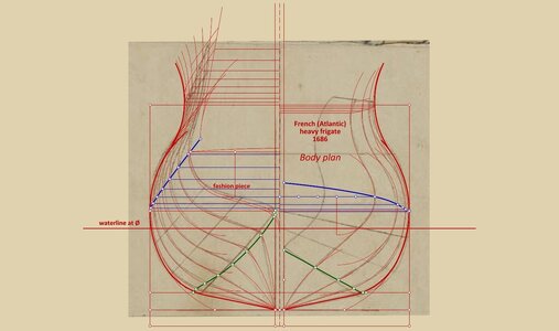
Basically, this stage completes the shaping of the underwater part of the hull, and the lines defining the leading frames, with the bilge sweeps highlighted, are also shown in the form of a body plan in the diagram below.


ViewCapture20240625_170711.jpg

.​
 
.​

Finally, some commentary is perhaps still required on a period insert attached to this plan on a separate sheet of paper, containing the body plan of the frigate designed by P. Chaillé. Its origin and purpose is, however, not entirely clear. It is true that there are diagonals drawn on it, but in fact these diagonals are not needed at all as a design basis for the frigate. For a change, they could just serve as a test of the smoothness of the hull surface obtained in the manner shown so far, but the contours of the frames and generally the hull lines drawn on this insert are not quite in line with the master plan either. Anyway, below is a reproduction of this insert with the hull lines as derived from the main plan superimposed.


ViewCapture20240625_192630.jpg


Thank you for your attention,
Waldemar Gurgul

.​
 
Last edited:
Back
Top