From manuscript to model

Joined
May 13, 2019
Messages
55
Points
113

Hi All,
In this thread, I decided to try and create, step by step, the shape and construction of an English merchant ship circa 1600 - a sort of online anatomy of the ship. Why 1600? First, it is the turn of the century and the reign of the mighty Queen Elizabeth I, a time of economic boom, international expansion and English naval triumph. And second, in my view, it is also a time when the conservative period ends and a more progressive and flexible period in shipbuilding begins.
My project and future plan will be called
English merchant ship, ca. 1600.
I already have a few plans in my collection, and then I even tried to make a design of the Elizabeth Jonas, one of the biggest Tudor galleons, but realized I lacked neither experience nor knowledge. On searching for information I came across a book by Michael Oppenheim "A history of the administration of the Royal Navy and of merchant shipping in relation to the navy from 1509 to 1660", and some facts from this work interested me greatly, namely the merchant fleet, which played a major role in the rise of England and its prosperity of that period. Of particular interest to me were the tables on pages 174-175 and the document of 1582, which gives the following data: The number of ships of 100 tons or more is 177, there are also 70 ships of 80 to 100 tons and 1,383 ships of 20 to 80 tons. At this point, it should be mentioned, that so-called Levantine Company, initially gave its shareholders a profit of 300%! Which set the stage for my final decision on my next project, which will hopefully also be a springboard to a more complex project like the Elizabeth Jonas plan.
 
First, I would like to mention the sources I will use for my reconstruction attempt. I have divided them into two criteria - General and Secondary:
These include historical and current literature and articles, but also archaeological finds and manuscripts.
General:
Sir Henry Mainwaring - The sea-mans dictionary
Matthew Baker- Fragments of Ancient English Shipwrighty
Peter Kirsch- Die Galeonen. Große Segelschiffe um 1600
Jon V. Pepper- Harriot's manuscript on shipbuilding and rigging (ca. 1608-1610)
A treatise on shipbuilding, c 1620. Edited by W. Salisbury
Brian Lavery- The Colonial Merchantman Susan Constant 1605
James Lees- The Masting and Rigging of English Ships of War 1625-1860
Anderson, R. C- The rigging of the ships in the days of spritsail topmast 1600-1720
Adrian B. Caruana- The History of English Sea Ordnance: 1523 - 1875
Frank Howard- Segel-Kriegsschiffe 1400-1860
and Articles
The Gresham Ship Project
Alderney Elizabethian wreck

Secondary sources:
Brian Lavery- Deane's Doctrine of Naval Architecture, 1670
Spectre, P.H. and D. Larkin- A Goodly Ship: The Building of the Susan Constant
Daeffler, Michel- Formes de carene et navires de combat
Mondfeld, Wolfram zu- Historische Schiffsmodelle
Basque Shipbuilding and Whaling in the 16th Century
William A. Baker- The Mayflower and other colonial vessels
Carvel Construction Technique: Skeleton-first, Shell-first : Fifth International Symposium on Boat and Ship Archaeology
 
I have planned a small ship of about 110 tons, from this possible Find proportions using the rules for tonnage measurement, around 1600 the rule (length of keel x width within plank x depth from top of keel to height of maximum breadth amidships) was divided by 100. Matthew Baker suggests as a general rule that the breadth should be between one half and one third of the length of the keel and the depth, one half to one third of the breadth, but that doesn't help me because there is clearly too little clues for that. Thomas Harriot's suggestion is more suitable, that length/width/depth should be 1 to 0.4 to 0.2, you can also interpret this differently: Breadth = 2xLength of keel/5 and Depth in hold= Breadth/2.
This gives the following dimensions for my reconstruction attempt:
Length of keel: 51.5ft
Breadth: 20.6ft
Depth in hold: 10.3ft
Tonnage: ca. 109
 
Last edited:
The Basic Profile
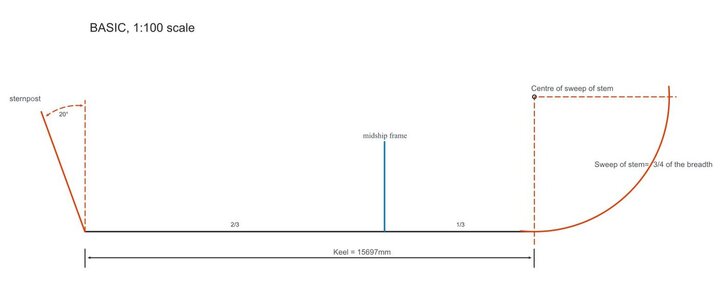
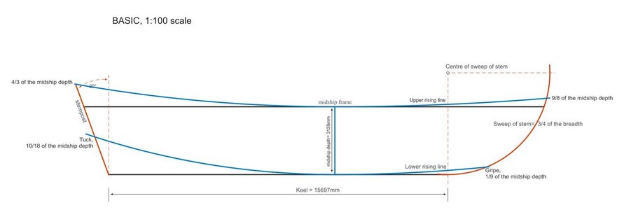
The stem is determined by an arc of a circle, and according to "A treatise on shipbuilding, c 1620" it should be between the breadth and three quarters of the breadth, or 0.791 of the breadth as the optimum value. Since this is a relatively small ship, I chose 3/4 of the breadth.
The sternpost was always straight and rose from the aft end of the keel at an angle of 20 degrees, its length never exceeding two-thirds of the breadth and never less than half the depth ("A treatise on shipbuilding, c 1620").
The keel is an important structural element of a ship (The length of an English ship around 1600 referred to the length of the keel!).
The midship frame and thus the greatest width of the ship was not in the middle but at the aft end of the front third of the keel.

001.JPG
 
The metric system is easier for me to use because I live in a country that uses this system.
It is also easier for me to work in 1:100 scale, however it is possible to save the finished plan in any scale.
 
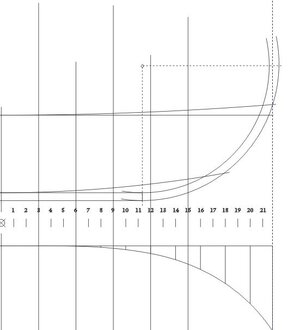
The basic shape of the hull is determined by the Rising and Narrowing lines.
It is important to look at the rising lines of the hull first.
The lower rising line is a curve and rises from the top of the keel at the midship frame forward and aft. The end point at the sternpost is below the tuck, Harriot states that the height of the end point is 10/18 of the depth of the midship frame. In the stem, the endpoint is at the greep, at a height of 1/9 of the depth of the midship frame.
The upper rising line connects the broadest parts of all frames. Its lowest point is at the midship frame, and the lower rising line rises forward and aft. The end point aft ends at the height of the upper edge of the sternpost with 4/3, the depth of the midship frame. At the stem, the end point is at the height of 9/8 of the depth of the midship frame.

002.JPG
 
.​

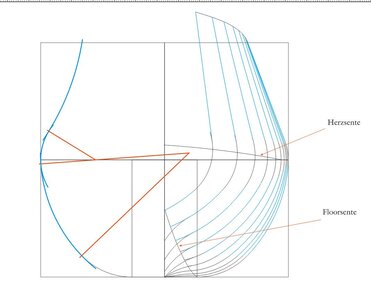
If you are following the Harriot manuscript, you should add a deadrise of at least 2 inches for the ship of a small size. Also, the line of greatest breadth ultimately has to terminate at the forward-most point of the stem, otherwise there will be geometry problems at the ship's bow. You can do this (according to the practices of the time, anyway) by adding a new arc of small radius, tangent to the line of greatest breadth which you already have.

.​
 
.​

I should also add that you are free to ignore the correction of the run of the line of greatest breadth at the stem, but then the contours of the frames in the bow area will have to be determined by battens (a kind of physical equivalent of design diagonals) rather than in a design-geometric way. This is actually also in line with the broad practices of the period.

.​
 
.​

If you are following the Harriot manuscript, you should add a deadrise of at least 2 inches for the ship of a small size. Also, the line of greatest breadth ultimately has to terminate at the forward-most point of the stem, otherwise there will be geometry problems at the ship's bow. You can do this (according to the practices of the time, anyway) by adding a new arc of small radius, tangent to the line of greatest breadth which you already have.

.​
Hello Waldemar,
Thank you for the comment, my drawings above are more for explanation than a full start, the line thickness at 1:100 scale is 0.5 mm, which is about 2 inches in the original. As for the line of greatest breadth, I agree with you, just wanted to show later
BL.JPG

But as to the question of deadrise and 2 inches, if I understand correctly, Here everything is a little unclear, according to some sources located on others not, in the Baker manuscript for example are present in some sketches, but for example already at Judeth Ship W.Borough is not shown, likewise there is none in the work of William A. Baker, and in both, perhaps the most important archaeological finds of Red Bay and Gresham Ship
 
.​

Hello again,

Naturally, you are perfectly right that there will always be some exceptions to the rule, and their conscious application may even make your reconstruction special or more attractive. However, as English (and other) sources suggest, deadrise was used in the overwhelming majority of cases. Simply for consideration:

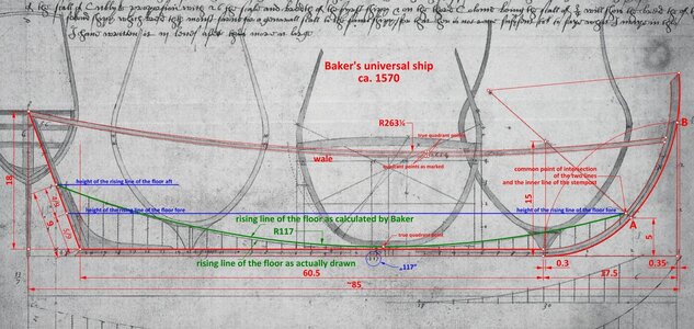
Mathew Baker (and indeed many others) did not always draw hollowing curves, because they were treated as a distinctly design-separated part of the hull. The sketch which I attach below is also quite telling. Baker mathematically correctly calculated the radius of the rising line of the floor (117 feet, meticulously written on his drawing), and which gives exactly 4 inches of deadrise, but he sloppily drew this line because he probably didn't want to waste time for accurate adjusting the flexible drawing batten. Something like this can indeed be misleading without careful verification.


ViewCapture20221130_112350.jpg


In fact, all English shipbuilding manuals clearly suggest the use of deadrise, by giving its dimensions.

Of course, the Gresham Ship has a deadrise, but with convex hollowing curves, and not concave. Otherwise the breadth of the floor would have to be zero or negative, which is extremely unlikely. See also the explanatory diagram 6–4 in the monograph of this ship.

The Red Bay Ship is certainly of Iberian origin, not English. Personally, I regard it as one of the few exceptions in this respect, perhaps built somewhat less professionally than the vast majority of the others. But I can only reiterate that taking such exceptions into account can also be attractive in itself. It is clearly your choice.

As for taking modern interpretations into account, I must admit that I was a bit confused by the title of the thread. If you find them authoritative, nothing should stop their use.

I wish you good luck with your project, especially as I also find these conceptual aspects particularly attractive.

.​
 
Last edited:
.​

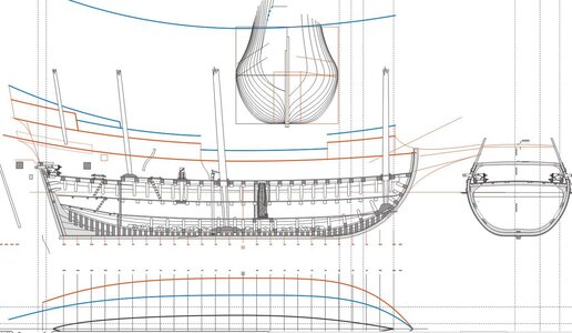
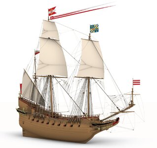
Well, I recently made such a historical reconstruction for the city museum in Gdańsk (Danzig) – the ship Sankt Georg of 1627 (it was a quite tough, over one year long experience). They are now building a wooden model according to these plans in 1:15 scale!

I imagine that you also intend to create something similar (and, as it happens, from my favourite period), just more as a ship designer and architect rather than someone using existing, modern plans. That's why I took the liberty of pointing out these details. You can still make an informed choice now, because later, at a more advanced stage of your project, it would already be a problem to implement them without destroying most of the work done so far (if you decide to do so, though).

Again, good luck with your ambitious project. I would be very happy to see another such reconstruction based on historical sources.

Reconstructed Sankt Georg 1627:

kolor-5 - Copy.jpg

.​
 
.​

Well, I recently made such a historical reconstruction for the city museum in Gdańsk (Danzig) – the ship Sankt Georg of 1627 (it was a quite tough, over one year long experience). They are now building a wooden model according to these plans in 1:15 scale!

I imagine that you also intend to create something similar (and, as it happens, from my favourite period), just more as a ship designer and architect rather than someone using existing, modern plans. That's why I took the liberty of pointing out these details. You can still make an informed choice now, because later, at a more advanced stage of your project, it would already be a problem to implement them without destroying most of the work done so far (if you decide to do so, though).

Again, good luck with your ambitious project. I would be very happy to see another such reconstruction based on historical sources.

Reconstructed Sankt Georg 1627:

your reconstruction looks very good

.​
Waldemar, your reconstruction looks very good!!!
 
Back
Top